OYE-MWCK02Safety Device Transmitter / Receiver
Miller Edge, Inc.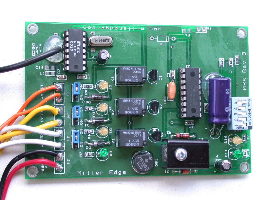
Click to zoom
Application Details
- Equipment Class
- DSR - Part 15 Remote Control/Security Device Transceiver
- Date of Grant
- Sep 16, 2003
- Application Purpose
- Original Equipment
- Date of Application
- Aug 21, 2003
- Equipment Note
- Safety Device Transmitter / Receiver
- Frequency Range
- 314.50000000 - 315.50000000
- Company
- Miller Edge, Inc.
- Country
- United States
Documents & Files
Document Text
Text extracted from the exhibit documents filed with the FCC. Open a document above to read the original.
Users Manual
The Communicator Wireless Transmitter/Receiver Installation Instructions TO REDUCE RISK OF SEVERE INJURY OR DEATH; READ AND FOLLOW ALL INSTALLATION INSTRUCTIONS TO PREVENT ELECTROCUTION DISCONNECT POWER AT FUSE BOX OR CIRCUIT BREAKER AND DOOR OPENER BEFORE WIRING PERMANENTLY. IMPROPER WIRING COULD CAUSE ELECTROCUTION OR DAMAGE TO CIRCUITRY. FOLLOW ALL LOCAL BUILDING CODES AND NATIONAL ELECTRICAL CODES. WARNING! TRANSMITTERINSTALLATION: 1- Remove lid from top of the MWCT-01 Transmitter to reveal mounting holes. Position the Transmitter near the bottom of the door and mark the mounting hole locations. 2. Remove the Transmitter from door, drill holes and mount the Transmitter with screws supplied. 3- Loosen wire fitting nut and feed the 4-wire sensing edge leads into the Transmitter housing trimming off excess wire. 4- Attach the 4-lead wires to the large green two-part terminal block connector as White White, Black Black. Tighten the wire fitting nut to assure water tight connection. 5- Adjust Dip Switches: 1= Channel Selector 2= Channel Selector 3= NOT USED 4= Address Selector 5= Address Selector (SEE FIGURE 1 FOR SWITCH CONFIGURATIONS.) 5- Be sure that the battery strap is connected and insert 9 Volt battery into the lid of the unit, and replace the lid. The Green LED light should light up indicating that the unit is functioning properly. RECEIVERINSTALLATION: 1- Hold the MWCR-01 Receiver up near the operator, mark and drill mounting holes. 2- Attach a 24VAC (at least 200mA) source to the red & black wires. A 12-28 VDC source may also be used. Polarity does not matter here. 3- Connect channel 1 to the white wires, channel 2 (if present) to the yellow wires, channel 3 to orange wires. The output relays will bear a load of 1A at 24VAC and 0.5A at 110VAC. Each channel has an associated YELLOW LED. The LED is illuminated when the channel is in a SAFE operating condition and will go out under fault condition. 4- There is a GREEN LED located near the dip switches which indicates SIGNAL ACQUIRED. It should turn on within a ew seconds of the transmitter contacting the receiver. 5- There is also a RED LED located in the same place, which signals MAINTENANCE REQUIRED. It will illuminate when there is a condition such as low battery or tampering. MILLER EDGE, INC. • P.O. Box 159 • West Grove, PA 19390 • 610-869-4422 • Fax: 610-869-4423 • 1-800-220-EDGE • www.milleredge.com MILLER EDGE, INC. • 6809 South Harl Avenue • Suite A • Tempe, AZ 85283 • 480-755-3565 • Fax: 480-755-3558 • 1-800-887-EDGE REV. 7-31-03 ON 5 4 3 21 RECEIVERINSTALLATION Cont. 6- Adjust Dip Switches: 1=Mode Selector 2= Mode Selector 3= NOT USED 4= Address Selector 5= Address Selector (SEE FIGURE 1 FOR SWITCH CONFIGURATIONS.) Modes are as follows: Switch 1 down, Switch 2 down: Mode Selected for Signal from one (1) Transmitter Switch 1 up, Switch 2 down: Mode Selected for Signal from two (2) Transmitters Switch 1 up, Switch 2 up: Mode Selected for Signal from two (3) Transmitters 7- Mount the Receiver near the operator using the 2 screws supplied. 8- Attach Coax Rigid Wire antenna. 9- Test door/gate operation to see that the system is functioning properly. OFF(0) ON 5 4 3 21 OFF(0) ON 5 4 3 21 OFF(0) ON 5 4 3 21 OFF(0) ON 5 4 3 21 OFF(0) ON 5 4 3 21 OFF(0) ON 5 4 3 21 OFF(0) ON 5 4 3 21 OFF(0) ON 5 4 3 21 OFF(0) RECEIVER SWITCH SETTING TRANSMITTER SWITCH SETTING 1 RECEIVER W/ 1 TRANSMITTER 1 RECEIVER W/ 2 TRANSMITTERS RECEIVER SWITCH SETTING TRANSMITTER #1 SWITCH SETTINGS TRANSMITTER #2 SWITCH SETTINGS 1 RECEIVER W/ 3 TRANSMITTERS LED DIAGNOSTICS (Inside Receiver Enclosure) SWITCH SHOWN IN DOWN (OFF) POSITION RECEIVER SWITCH SETTING TRANSMITTER #1 SWITCH SETTINGS TRANSMITTER #2 SWITCH SETTINGS TRANSMITTER #3 SWITCH SETTINGS FIGURE 1 POWER (Green) CHANNEL 1 RELAY CHANNEL 2 RELAY CHANNEL 3 RELAY NOTE: RELAY LIGHTS ARE YELLOW MILLER EDGE, INC. • P.O. Box 159 • West Grove, PA 19390 • 610-869-4422 • Fax: 610-869-4423 • 1-800-220-EDGE • www.milleredge.com MILLER EDGE, INC. • 6809 South Harl Avenue • Suite A • Tempe, AZ 85283 • 480-755-3565 • Fax: 480-755-3558 • 1-800-887-EDGE
Block Diagram
Appendix E EUT Block Diagram and Schematics RECEIVER BLOCK DIAGRAM RECEIVER SCHEMATICS TRANSMITTER BLOCK DIAGRAM TRANSMITTER SCHEMATICS
External Photos
Appendix C Photographs of EUT Receiver, Open View Receiver, FCC Label Location Receiver, Component Side of Printed Circuits Board Receiver, Circuit Side of Printed Circuits Board Transmitter, Open View Transmitter, FCC Label Location Transmitter, Component Side of Printed Circuits Board Transmitter, Circuit Side of Printed Circuits Board
ID Label/Location Info
Appendix C Photographs of EUT Receiver, Open View Receiver, FCC Label Location Receiver, Component Side of Printed Circuits Board Receiver, Circuit Side of Printed Circuits Board Transmitter, Open View Transmitter, FCC Label Location Transmitter, Component Side of Printed Circuits Board Transmitter, Circuit Side of Printed Circuits Board
ID Label/Location Info
2. EUT LABELING 2.1. FCC Label The FCC Notice is in the Unit Operation manual and the FCC statement word is on the label. The following is a sample of the FCC ID label to be used on the EUT. Model No.: MWCT01 or MWCR01 Part No.: Ser. No.: This device is complies with Part 15 of the FCC Rules. Operation is subject to the following two conditions: (1) This device may not cause harmful interference, and (2) This device must accept any interference received, including interference that may cause undesired operation. Complies with Part 15, FCC Rules. FCC ID: OYE-MWCK02 2.2. Location of Label on EUT The location of the FCC compliance label is at the rear of EUT for receiver unit and at the bottom of EUT for transmitter. The location of label is shown on EUT photograph in Appendix C.
Internal Photos
Appendix C Photographs of EUT Receiver, Open View Receiver, FCC Label Location Receiver, Component Side of Printed Circuits Board Receiver, Circuit Side of Printed Circuits Board Transmitter, Open View Transmitter, FCC Label Location Transmitter, Component Side of Printed Circuits Board Transmitter, Circuit Side of Printed Circuits Board
Operational Description
3. SYSTEM TEST CONFIGURATION AND JUSTIFICATION 3.1. EUT Operation Mode and Test Justification The receiver was tested in a configuration whereby all of the available input/output impedance matched loads are attached and functional. The receiver operates a 24 VAC external wall mount ac adaptor power source. The chosen operating mode fully exercises and duplicates all normal activity that may be expected by a user. This operation provides the worst case for EMC, in that all devices on EUT are active and working normally. The transmitter was only performed radiated emission test. Because of the transmitter operates with an internal 9 volts potable battery. Therefore, no conducted emission testing was performed for the transmitter. 3.2. EUT Exercise Software No software was used to exercise the test sample. 3.3. General and Special Conditions No alternate test method or special accessories were used to achieve compliance. 3.4. EUT Modifications No modification was required to achieve compliance. 3.5. Cable Configurations Followings are cables used in the compliance test. a. AC Adaptor cable; Power to receiver, unshielded 2 conductor cable, one end fix to wall mount ac adaptor. b. 8 of AWG #20 wires; Connect between receiver and load terminal, unshielded 1 conductor wire.
Schematics
Appendix E EUT Block Diagram and Schematics RECEIVER BLOCK DIAGRAM RECEIVER SCHEMATICS TRANSMITTER BLOCK DIAGRAM TRANSMITTER SCHEMATICS
Test Report
(FCC Registration Number: 90701) 3 Adelphia Lane, Chester Springs, PA 19425, USA Tel: (610) 827-3031 Fax: (610) 827-3032 ------------------------------------------------------------------------------------------------------------------------------------------------------ FCC MEASUREMENT REPORT For Miller Edge, Inc. Gate and Door edge Transmitter and Receiver Kit Model MWCK01 Test and evaluation performed by International Technologies Report No.: ME-030721-FCC ------------------------------------------------------------------------------------------------------------- FCC ID: OYE-MWCK01 International Technologies ME-030721-FCC Sheet 2 of 36 Revision - 0 Agency Declaration/Disclaimer International Technologies reports apply only to the specific samples tested under stated test conditions. It is the manufacturer’s responsibility to assure that additional production units of this model are manufactured with identical electric and mechanical components. International Technologies shall have no liability for any deductions, inferences or generalizations drawn by the client or others from International Technologies issued reports. This report is the confidential property of the client. As a mutual protection to our clients, the public and ourselves, extracts from the test report shall not be reproduced except in full without our written approval. This report is to comply the FCC Rules in accordance CFR 47, Part 15 Subpart B and C, not related to any grant or submissions. Document Title FCC Measurement Report Miller Edge, Inc. Gate and Door Edge Transmitter and Receiver Kit Model MWCK01 Number ME-030721-FCC Revision 0 Date July 21, 2003 FCC ID: OYE-MWCK01 International Technologies ME-030721-FCC Sheet 3 of 36 Revision - 0 Table of Contents SUMMARY of MEASURMENT REPORT.....................................................................................5 Purpose ....................................................................................................................................................................... 5 Result.......................................................................................................................................................................... 5 1. General Information ......................................................................................................................................... 6 1.1. Equipment Units Tested (EUT) Description ............................................................................................ 6 1.2. Related Submittal(s) / Grant(s) ................................................................................................................. 6 1.3. Tested System Details.............................................................................................................................. 6 1.4. Applicable Standard ................................................................................................................................. 7 1.5. Location of Test Site................................................................................................................................. 7 2. EUT Labeling................................................................................................................................................... 8 2.1. FCC Label ................................................................................................................................................ 8 2.2. Location of Label on EUT........................................................................................................................ 8 3. System Test Configuration and Justification.................................................................................................... 9 3.1. EUT Operation Mode and Test Justification ............................................................................................ 9 3.2. EUT Exercise Software ............................................................................................................................ 9 3.3. General and Special Conditions................................................................................................................ 9 3.4. EUT Modifications ................................................................................................................................... 9 3.5. Cable Configurations................................................................................................................................ 9 4. Block Diagram of EUT .................................................................................................................................. 10 4.1. Block Diagram Description .................................................................................................................... 10 5. Conducted Measurement Procedures ............................................................................................................. 11 5.1. Conducted Test Set-up............................................................................................................................ 11 5.2. Preliminary Conducted Test ....................................................................................................................... 11 5.3. Final Conducted Test.................................................................................................................................. 11 6. Radiated Measurement Procedures ................................................................................................................ 12 6.1. Radiated Test Set-up............................................................................................................................... 12 6.2. Preliminary Radiated Test ...................................................................................................................... 12 6.3. Final Radiated Test..........................................…
Text truncated - open the document above for the full version.
Test Setup Photos
Appendix D Photographs of Test Setup Radiated Test Set-up for Receiver Conducted Test Set-up for Receiver Radiated Test Set-up for Transmitter
Contact Information
Applicant
Tim Castello
Technical Contact
Miller EdgeMichael L Anderson
[email protected]610-869-4422
300 N Jennersville Rd · West Grove, Pennsylvania · United States
Test Firm
International TechnologiesYong Park
Technical Specifications
| # | Rule Parts | Frequency Range | Power Output |
|---|---|---|---|
| 1 | 15.231 | 314.5 MHz - 315.5 MHz | - |
Other Applications from Miller Edge, Inc.

OYE-MEL916
Aug 27, 2014Monitored Edge Link
Equipment Class
DXX - Part 15 Low Power Communication Device Transmitter
OYE-MEL315
Aug 11, 2014Monitored Edge Link
Equipment Class
DSC - Part 15 Security/Remote Control Transmitter
OYE-MTF10
Jun 22, 2014RF Link
Equipment Class
DXX - Part 15 Low Power Communication Device Transmitter
OYE-MWT120
May 01, 2013318 MHz SINGLE CHANNEL TRANSMITTER
Equipment Class
DSC - Part 15 Security/Remote Control Transmitter
OYE-MDTR303
Feb 06, 2012CONTROL ALARM TRANSMITTER
Equipment Class
DSC - Part 15 Security/Remote Control Transmitter