P3O97802Telematic Tracking System
META System S.p.A.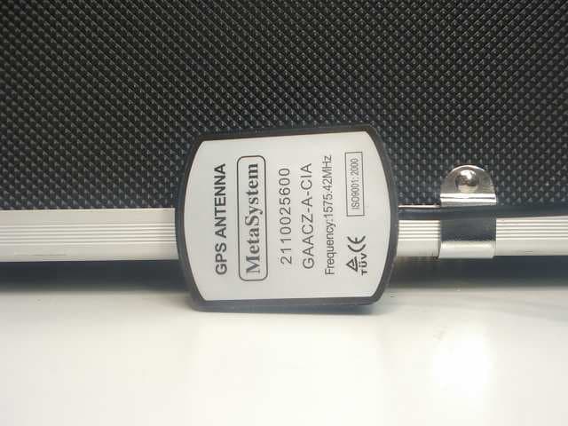
Click to zoom
Application Details
- Equipment Class
- PCB - PCS Licensed Transmitter
- Date of Grant
- Jun 27, 2010
- Application Purpose
- Original Equipment
- Date of Application
- Jun 24, 2010
- Equipment Note
- Telematic Tracking System
- Frequency Range
- 1850.20000000 - 1909.80000000
- Company
- META System S.p.A.
- Country
- Italy
Documents & Files
Document Text
Text extracted from the exhibit documents filed with the FCC. Open a document above to read the original.
Users Manual
SAT RC 09 INSTALLATION MANUAL CAUTION - Only carry out the operations described in this manual. - The installer is not authorized to remove the warranty seals or to access the interior parts of the products or accessories. - The installer is not authorized to modify and/or adapt the product or the relative accessories. - The manufacturer declines all liability for damage to persons and/or property caused by incorrect installation of the product. TECHNICAL SPECIFICATIONS Dimensions and weight:....................................................................................104X75X27, 168g Power supply voltage:................................................................................................12 VDC Temperature:..........................................................................................................-25º+70ºC Power input*:.............................................................................................................<2mA *With the peripheral device connected, the GPS off, Sat Programmer disconnected and the internal buffer battery charged. Maximum current:.............................................................................................................<210mA DISCONNECT THE VEHICLE’S BATTERY GROUND BATTERY POSITIVE (+12V) IGNITION KEY POSITIVE (+15) GSM ANTENNA 1 EN PRESS TO RELEASE GPS ANTENNA Release and position the lever as shown in the figure before connecting the 18-pin loose connector to the terminal. CONNECTOR CONNECTIONS Lock the connector to the terminal by positioning the lever as shown in the figure. Connect the connectors to the terminal PHASE 2 PHASE 3 PHASE Fig.2 Fig.3 Fig.4 WARNING: make sure that the connector is inserted and locked to the terminal in the correct way. * : MANDATORY 5040273800 +15 5A SAT PROGRAMMER * +12 GND Fig.1 DARK BLUE MAROON GENERAL LAYOUT See pic. 5 • Position the device in a concealed part of the vehicle, inside the passenger compartment • To allow the diagnosis and testing operations to be carried out without difficulty, it is essential to install the device in a position where it can be easily reached with the cable of the Sat programmer. • Do not install the device under a mat, where it could be trodden on or crushed by a load. • It is advisable to lock the device to a rigid part of the vehicle. HOW TO POSITION THE DEVICE HOW TO POSITION THE CRASH SENSOR GSM ANTENNA ONCE YOU HAVE CHOSEN THE POSITION FOR THE ANTENNA, MAKE SURE THAT THE RECEPTION IS GOOD BEFORE FIXING IT IN PLACE: - CONNECT THE SAT PROGRAMMER AND TEST TO MAKE SURE THAT EVERYTHING WORKS PROPERLY BY MEANS OF THE APPROPRIATE FUNCTION (CONSULT THE RELATIVE MANUAL). IT MUST NOT BE VISIBLE OR EASILY ACCESSIBLE FROM THE OUTSIDE DO NOT COVER WITH PARTS OR METALLIC PAINTS CAREFULLY CLEAN THE FIXING SURFACE THE ANTENNA IS RESIN- COATED AND CAN THEREFORE BE INSTALLED ON THE OUTSIDE OF THE VEHICLE (E.G. UNDER THE MUDGUARDS, IN A HEADLIGHT......) HOW TO CONNECT THE GSM ANTENNA Fig.6 Fig. 7Fig. 8Fig. 9 Fig. 10 FIXING WITH SPACER Use the supplied spacer to install the sensor on a flat surface, opposite the fastening tabs (e.g. longitudinal frame members on the PASSENGER’S SIDE, surfaces BELOW the sensor). The sensor must NOT be turned. Comply with the position indicated on the sticker affixed to the side of the sensor. HOW TO INSERT THE SPACER FIXING IN THE VEHICLE Pay particular attention to the direction in which the spacer is inserted. ! T O P TOP OF VEHICLE LEFT SIDE OF VEHICLE RIGHT SIDE OF VEHICLE FRONT OF VEHICLE • Fix the sensor temporarily in place with the screw. • Check the position of the sensor by means of the relative Sat Programmer menu. • Fix the sensor permanently in place. X Y X TOP OF VEHICLE LEFT SIDE OF VEHICLE RIGHT SIDE OF VEHICLE FRONT OF VEHICLE X Y FRONT CONNECTION CRASH SENSOR CAUTION! CHECK THE CORRECT CONNECTION CLICK! CLICK! Fig.5 OK OK OK OK Y X 0 THE ANTENNA IS RESIN- COATED AND CAN THEREFORE BE INSTALLED ON THE OUTSIDE OF THE VEHICLE (E.G. UNDER THE MUDGUARDS, IN A HEADLIGHT......) 90° NO OK IT MUST NOT BE VISIBLE OR EASILY ACCESSIBLE FROM THE OUTSIDE DO NOT COVER WITH PARTS OR METALLIC PAINTS KOOK ONCE YOU HAVE CHOSEN THE POSITION FOR THE ANTENNA, MAKE SURE THAT THE RECEPTION IS GOOD BEFORE FIXING IT IN PLACE: - DRIVE THE VEHICLE TO AN OPEN SPACE, WELL AWAY FROM BUILDINGS OF A CERTAIN HEIGHT - CONNECT THE SAT PROGRAMMER AND TEST TO MAKE SURE THAT EVERYTHING WORKS PROPERLY BY MEANS OF THE APPROPRIATE FUNCTION (CONSULT THE RELATIVE MANUAL). GPS ANTENNA HOW TO CONNECT THE GPS ANTENNA HOW TO FIX THE ANTENNA: - ON METAL PARTS WITHOUT THE USE OF THE DOUBLE-SIDED ADHESIVE MATERIAL (THE ANTENNA IS MAGNETIC) - ON PLASTIC PARTS USING THE DOUBLE-SIDED ADHESIVE MATERIAL SUPPLIED IN THE KIT CAREFULLY CLEAN THE FIXING SURFACE Fig. 11 OK OK OK OK NOTE:This equipment has been tested and found to comply with the limits for a Class B digital device, pursuant to Part 15 of the FCC Rules. These limits are designed to provide reasonable protection against harmful interference in a residential installation. This equipment generates, uses and can radiate radio frequency energy and, if not installed and used in accordance with the instructions, may cause harmful interference to radio communications. However, there is no guarantee that interference will not occur in a particular installation. If this equipment does cause harmful interference to radio or television reception, which can be determined by turning the equipment off and on, the user is encouraged to try to correct the interference by one or more of the following measures: - Reorient or relocate the receiving antenna. - Increase the separation between the equipment and receiver. - Connect the equipment into an outlet on a circuit different from that to which the receiver is connected. - Consult the dealer or an experienced radio/TV technician for help. Meta System S.p.A. Model: SAT RC 09 FCC ID.: P3O97802 This device complies with Part 15 of the FCC rules subject to the follo…
Text truncated - open the document above for the full version.
Operational Description
Operational Description for Telematic Tracking System called SAT RC 09 The product is a vehicle tracking system use to follow the vehicle and to allow the recovery of the vehicle in case of stolen, theft or after crash. the product is fitted on the vehicle by means a 3 wires connection, to simplify the installation on all the vehicle range. The harness is provided with all the wires black, to know the wire to be use a number is placed on the part that will be sliced before connection. The product contains a Jasper SIM card to manage only M2M service, to manage the data transmitted the SOC ( Security Operational Center) is needed. The system is used to count the mileage of the vehicle the system contains a GPS localizing system to know the positions and to send this information, periodically, to the operating centre. Information are related to time, positioning and this information are matched with the area to know road type, highway, urban ecc.th scope is to provide insurance service at the user. The PCB is build around a single motherboard, two layers of components, that contains the functions to manage, tracking, communications, tilt sensor. The communication with the operating centre, to collect data, is based on GPRS communication . The internal modem is a TELIT GE864 Quad Band module the system is managed from an internal microcontroller M32C87A. from Renesas, that manage all the I/O, tilt sensor, and the user interface as well. The frequencies of the main clock is 10 MHz, an additional quartz for with EEPROM external memory of 256 bytes. The microprocessor is equipped with hardware and software watchdog; The product is for vehicle application, the power supply is the 12 Volt DC provided from the main battery. The product contains an internal battery backup pack, 7,2 V NiCd, to allow the functionality of the system to avoid manipulation or frauds. The products is provide with 2 antennas, one for the GPS receiver and one for the GPRS bi-directional communication. The GPRS antenna gains is from 0~0.5 dBi @ 880 – 960 MHz from 0.5 ~ 1 dBi @ 1710 – 1990 MHz. The system is installed in the vehicle by the dealer or by the authorized centre and it is completely invisible at the end user. No operating manual is provided because the user do not use the product but the system is use for the vehicle tracking. The product is provided only with the installation instruction. Safety and reliability The following points outline the safety and reliability factors which have been considered in the design of the units. • Reverse polarity protection of the unit • Load dump protection • All the connections, except antennas, are on AMP MQS 18 poles connector; • Built-in Hardware watch-dog for microprocessor to prevent any lock-up • PCB with large ground plate to get better rejection to electromagnetic disturbance INPUT Permanent 12 V power supply (+30) Ignition (+15) Power negative supply (-31) GPRS antenna and GPS antenna are connected with Fkra connectors with secondary lock.
Parts List/Tune Up Info
3020097802_C36 SAT RC 09 TELIT ANTENNA STAMPATO - Revised: martedì, ottobre 20, 2009 3020097802 Revision: 0 METASYSTEM S.P.A. PROPERTY ALL RIGHTS RESERVED ART.1151-1/2/3 IL TECNICO PROGETTISTA: R.ROMAGNOLI IL TECNICO DISEGNATORE: R. ROMAGNOLI DVP-S 159 REV.000 21/10/02 Bill Of Materials Oct 20,2009 14.23.43 Page: 1 Item Quantity Reference Part ____________________________________________________________________________________ ____ ------ Componenti SMD ------------------------------------------------------ 1 12 'C90,R28,R29,R30,R31, 1550003900,0,SMD,0402,,1/16W,5% R32,R33,R34,R35,R36,R37 R38 2 2 'L10,'L11 1550000900,0,SMD,0603,,1/10W 3 2 C1,C2 1500034300,100U,SMD,C-SIZE-C,6V3 4 2 C3,C4 1500028600,2U2,SMD,0805_C_DX,10V,,10%,,,X7R,AUTOM 5 2 C5,C6 1500024500,100N,SMD,0603,50V,,10%,,,X7R,AUTOM 6 2 C7,C8 1500013500,330P,SMD,0402,50V,,,,,C0G 7 1 C9 1500015400,1N,SMD,0402,50V,,10%,,,X7R 8 2 C10,C11 1500028700,2U2,SMD,0805_C_DX,25V,,10%,,,X7R 9 1 C12 1500034800,220U,SMD,CESMD6X6X5.5,16V,,20%,,,-55/+105C 10 9 C13,C14,C15,C16,C17,C18, 1500009000,33P,SMD,0402,50V,,,,,C0G C19,C20,C21 11 1 C22 1500034100,100U,SMD,CESMD6X6X8,35V 12 1 C23 1500003700,1P8,SMD,0402,50V,,+/-0.25PF,,,C0G 13 22 C24,C25,C26,C27,C28,C29, 1500022700,100N,SMD,0402,16V,,,,,X7R C30,C31,C32,C33,C34,C35 C36,C37,C38,C39,C40,C41 C42,C43,C44,C45 14 1 C46 1500009800,47P,SMD,0402,50V,,10%,,,C0G 15 3 C47,C48,C49 1500007900,18P,SMD,0402,50V,,5%,,,C0G 16 20 C50,C51,C52,C53,C54,C55, 1500026900,1U,SMD,0402,10V,,10%,,,X5R C56,C57,C58,C59,C60,C61 C62,C63,C64,C65,C66,C67 C68,C69 17 2 C70,C71 1500027900,1U,SMD,0603,25V,,10%,,,X5R,AUTOM 18 1 C72 1500034600,150U,SMD,C-SIZE-D,6V3 19 7 C73,C74,C75,C76,C77,C78, 1500019400,10N,SMD,0402,25V,,,,,X7R C79 20 5 C80,C81,C82,C83,C84 1500028900,4U7,SMD,0805_C_DX,16V,,10%,,,X5R,AUTOM 21 1 C85 1500006900,8P2,SMD,0402,50V,,,,,C0G 22 34 C86,C87,C88,C89,C90,C91, 1500011100,100P,SMD,0402,50V,,5%,,,C0G C92,C93,C94,C95,C96,C97 C98,C99,C100,C101,C102 C103,C104,C105,C106 C107,C108,C109,C110 C111,C112,C113,C114 C115,C116,C119,C120,C121 Page 1 3020097802_C36 23 2 C117,C118 1500026300,470N,SMD,0402,6V3,,10%,,,X5R 24 1 D1 1520005800,BAV99,SMD,SOT23_DX,70V,,,200MA,,150C 25 1 D2 1520008100,BAV99W,SMD,SOT-323_DX,,,,,,-65/+150C 26 1 D3 1520010400,SCHOTTKY 40V-2A,SMD,SMD-DO-220AA,40V,,,2A,,-55/+150C SAT RC 09 TELIT ANTENNA STAMPATO - Revised: martedì, ottobre 20, 2009 3020097802 Revision: 0 METASYSTEM S.P.A. PROPERTY ALL RIGHTS RESERVED ART.1151-1/2/3 IL TECNICO PROGETTISTA: R.ROMAGNOLI IL TECNICO DISEGNATORE: R. ROMAGNOLI DVP-S 159 REV.000 21/10/02 Bill Of Materials Oct 20,2009 14.23.43 Page: 2 Item Quantity Reference Part ____________________________________________________________________________________ ____ 27 3 D4,D5,D6 1520007400,1A 400V,SMD,SOD-123,400V,,,1A 28 1 D8 1520009500,SCHOTTKY,SMD,SMD-DO-214AC,40V,1/2W,,1A 29 2 D9,D12 1520008000,BAV70W,SMD,SOT-323_DX,,,,,,-65/+150C 30 1 D10 1520010300,SCHOTTKY 60V,SMD,SOT23_DX,60V,,,900MA 31 1 D11 1520009300,BAS70-05,SMD,SOT23_DX,,,,,,-55 +125C 32 1 DZ1 1520003900,BZX84-27V,SMD,SOT23_DX,27V,0W3,5% 33 1 DZ2 1520002400,BZX84-15V,SMD,SOT23_DX,15V,0W3,5% 34 1 DZ3 1080007000,PESD12VL1BA,SMD,SOD-323 35 1 DZ4 1520004400,PLVA,SMD,SOT23_DX,5V,,4%,650MA 36 1 DZ5 1520000300,BZX84-3V3,SMD,SOT23_DX,3V3,0W3,5% 37 6 DZ6,DZ7,DZ8,DZ9,DZ10, 1520003800,CAN-ESD,SMD,SOT23_DX,24V DZ12 38 1 DZ11 1520000400,BZX84-4V7,SMD,SOT23_DX,4V7,0W3,5%,,,150C 39 1 EC1 2500005800,CON-18POLI-MAS-90-CS,SMD,CONN-18POLI-O-E10180 40 1 EC2 2500002500,CON-SMD RF GSC,SMD,GSC-MALE 41 1 EC3 2050018100,CONN-SMD.FAKRA-PLUG-,SMD,SMB-CARLOCK-PIP 42 1 EC4 2500001500,CONN-40P-P0.5-V,SMD,CONN-JMD-40P-V 43 1 EC5 2050018200,CONN-SMD.FAKRA-PLUG-,SMD,SMB-CARLOCK-PIP 44 1 EC6 2500007400,ZOCC-SIM-BRIDGEBLOCK,SMD,SIM-HEADER-BRIDGEBLO 45 1 L1 1150009700,FILTRO-EMI-SMD,SMD,0603 46 1 L2 1610009000,10UH,SMD,CDRH4D22,,,,800MA 47 9 L3,L4,L5,L6,L7,L8,L9, 1150009800,FILTRO-EMI-SMD,SMD,0603,,,,3A L10,L11 48 1 L12 1610004200,47NH,SMD,0402 49 1 L13 1610002300,10NH,SMD,0402 50 3 L14,L15,L16 1610005000,100NH,SMD,0402 51 1 L17 1610008800,4U7H,SMD,CDRH4D22,,,25%,2A2 52 1 Q1 1590012500,PUMH2,SMD,SC70-6,,,,100MA Page 2 3020097802_C36 53 1 Q2 1590000800,BC857B,SMD,SOT23_DX 54 2 Q3,Q4 1590010700,BCR116W,SMD,SOT-323_DX 55 1 Q5 1590012600,BC857BS,SMD,SC70-6,,,,100MA 56 1 Q6 1590006900,PNP-1A-45V,SMD,SOT-89,45V,,,1A 57 1 Q7 1590011100,BCR198,SMD,SOT-323_DX 58 1 Q8 1590000500,BC807,SMD,SOT23_DX 59 1 Q9 1590002100,MMBTA42,SMD,SOT23_DX,300V,,,500MA 60 1 Q10 1590009000,STN3PF06,SMD,SOT-223_DX,60V,,,2A5 61 2 Q11,Q12 1590007100,30V-2A,SMD,SOT23_DX,30V,,,2A 62 4 Q13,Q14,Q15,Q19 1590011300,BCR22,SMD,SC70-6 63 3 Q16,Q17,Q18 1590005600,BSS138,SMD,SOT23_DX,50V,,,200MA 64 2 QZ1,QZ2 1150009100,32K768HZ,SMD,Q-A05566,,,,,32K768HZ 65 7 R1,R2,R3,R4,R5,R6,R7 1550013700,1K,SMD,0402,,1/16W,5% 66 1 R8 1550019800,15K,SMD,0402,,1/16W,5% 67 1 R9 1550001200,1,SMD,1206,,1/4W,5% 68 1 R10 1550008800,100,SMD,0805_R_DX,,1/8W,5% SAT RC 09 TELIT ANTENNA STAMPATO - Revised: martedì, ottobre 20, 2009 3020097802 Revision: 0 METASYSTEM S.P.A. PROPERTY ALL RIGHTS RESERVED ART.1151-1/2/3 IL TECNICO PROGETTISTA: R.ROMAGNOLI IL TECNICO DISEGNATORE: R. ROMAGNOLI DVP-S 159 REV.000 21/10/02 Bill Of Materials Oct 20,2009 14.23.43 Page: 3 Item Quantity Reference Part ____________________________________________________________________________________ ____ 69 7 R11,R12,R13,R14,R15, 1550025900,220K,SMD,0402,,1/16W,5% R126,R127 70 1 R16 1560035400,150K,SMD,0603,,1/10W,1% 71 15 R17,R18,R19,R20,R21,R22, 1550009200,100,SMD,0402,,1/16W,5% R23,R24,R25,R26,R27 R130,R131,R132,R133 72 1 R41 1550003200,4R7,SMD,0805_R_DX,,1/8W,5% 73 3 R42,R43,R44 1560033600,47K,SMD,0603,,1/10W,1% 74 1 R45 1550007400,47,SMD,0402,,1/16W,5% 75 2 R46,R128 1550013500,1K,SMD,0805_R_DX,,1/8W,5% 76 9 R47,R48,R49,R50,R51,R52, 1550028700,1M,SMD,0402,,1/16W,5% R53,R54,R55 77 1 R56 1560035200,130K,SMD,0603,,1/10W,1% 78 2 R57,R58 1560037100,620K,SMD,0603,,1/10W,1% 79 4 R59,R60,R61,R62 1550009000,100,SMD,0603,,1/10W,5% 80 43 R63,R64,R65,R66,R67,R…
Text truncated - open the document above for the full version.
RF Exposure Info
Prediction of MPE limit at a given distance M W-CBDA-SMR-10W80-PS8, Uplink Outdoor Donar Antenna Equation from page 18 of OET Bulletin 65, Edition 97-01where: S = power density P = power input to the antennaG = power gain of the antenna in the direction of interest relative to an isotropic radiatorR = distance to the center of radiation of the antenna Maximum peak output power at antenna input terminal: 26.70 (dBm) Maximum peak output power at antenna input terminal: 467.7351413 (mW) Antenna gain(typical): 2.6 (dBi) Maximum antenna gain: 1.819700859 (numeric) Prediction distance: 20 (cm) Prediction frequency: 1880 (MHz) MPE limit for uncontrolled exposure at prediction frequency: 1 (mW/cm^2) Power density at prediction frequency: 0.169329 (mW/cm^2) Maximum allowable antenna gain: 10.31269855 (dBi) Margin of Compliance: 7.712698554 2 4 R PG S π =
Test Report
www.nemko.com Nemko Spa Via del Carroccio, 4 – I 20046 Biassono (Italy) Report number: 141978TRFWL Apparatus: GPS/GSM Vehicle Tracking Systems Applicant: Meta System S.p.A. Via Galimberti, 9 42100 Reggio Emilia (RE) FCC ID: P3O97802 Test specification: Title 47 – Telecommunication Chapter I – Federal Communications Commission Subchapter A – General Part 24 – Personal Communication Services Subpart E – Broadband PCS Reviewed by: 2010-06-01 Signature Date Paolo Barbieri, Wireless/EMC Specialist Tested by: 2010-06-01 Signature Date Daniele Guarnone, Wireless/EMC Specialist Nemko Spa authorizes the applicant to reproduce this report provided it is reproduced in its entirety and for use by the company’s employees only. Any use which a third party makes of this report, or any reliance on or decisions to be made based on it, are the responsibility of such third parties. Nemko Spa accepts no responsibility for damages, if any, suffered by any third party as a result of decisions made or actions based on this report. This report shall not be reproduced except in full without the written approval of the testing laboratory. Page 2 of 37 Table of contents Section 1: Report summary................................................................................................................... 3 Section 2: Equipment under test .......................................................................................................... 4 2.1 Identification of equipment under test (EUT)......................................................................... 4 2.2 Accessories and support equipment ..................................................................................... 4 2.3 EUT description .................................................................................................................... 5 2.4 Technical specifications of the EUT ...................................................................................... 5 2.5 EUT setup diagram............................................................................................................... 6 2.6 Operation of the EUT during testing ..................................................................................... 7 2.7 Modifications incorporated in the EUT .................................................................................. 7 Section 3: Test conditions .................................................................................................................... 8 3.1 Deviations from laboratory tests procedures......................................................................... 8 3.2 Test conditions, power source and ambient temperatures .................................................... 8 3.3 Measurement uncertainty ..................................................................................................... 9 3.4 Test equipment..................................................................................................................... 9 Section 4: Result summary ................................................................................................................. 10 4.1 Test results ......................................................................................................................... 10 Appendix A: Test results ..................................................................................................................... 11 Clause 24.232(c) Equivalent isotropically radiated power limits........................................................ 11 Clause 24.238(b) Occupied bandwidth............................................................................................. 16 Clause 24.238(a) Spurious emissions at antenna terminal............................................................... 21 Clause 24.238(a) Field strength of spurious radiation ...................................................................... 26 Clause 24.235 Frequency stability.................................................................................................... 34 Appendix B: Block diagrams of test set-ups ..................................................................................... 37 Section 1: Report summary Report number: 141978TRFWL Nemko Spa Via del Carroccio, 4 – I 20046 Biassono (Italy) Specification: FCC 24 Subpart E Page 3 of 37 Section 1: Report summary This report contains an assessment of apparatus against specifications based upon tests carried out on samples submitted at Nemko S.p.A. Test specification: FCC Part 24 Subpart E, Broadband PCS Compliance status: Complies Exclusions: None Non-compliances: None Report release history: first release Test location: Nemko Spa Via del Carroccio, 4 – I 20046 Biassono (Italy) Note that the results contained in this report relate only to the items tested and were obtained in the period between the date of initial receipt of samples and the date of issue of the report. This test report has been completed in accordance with the requirements of ISO/IEC 17025. Nemko S.p.A. authorizes the applicant to reproduce this report provided it is reproduced in its entirety and for use by the company’s employees only. Any use which a third party makes of this report, or any reliance on or decisions to be made based on it, are the responsibility of such third parties. Nemko S.p.A.. accepts no responsibility for damages, if any, suffered by any third party as a result of decisions made or actions based on this report. Section 2: Equipment under test Report number: 141978TRFWL Nemko Spa Via del Carroccio, 4 – I 20046 Biassono (Italy) Specification: FCC 24 Subpart E Page 4 of 37 Section 2: Equipment under test 2.1 Identification of equipment under test (EUT) The following information identifies the EUT under test: Type of equipment: GPS/GSM Vehicle Tracking Systems Product marketing name: Model number: SAT RC09 Serial number: 100200230260544101 Nemko sample number: 141978 FCC ID: P3O97802 Date of receipt: …
Text truncated - open the document above for the full version.
Test Setup Photos
Conducted Emissions Radiated Emissions Frequency stability test
Contact Information
Applicant
Giorgio Maldini(Product Homologation Manager)
Technical Contact
Meta System S.p.A.Roberto Romagnoli
[email protected]390522364256
Via Galimberti 9 · Reggio Emilia · Italy
Non-Technical Contact
Meta SystemGiorgio Maldini
[email protected]390522364256
Test Firm
Nemko SpARoberto Franza
Technical Specifications
| # | Rule Parts | Frequency Range | Power Output | Emission | Tolerance |
|---|---|---|---|---|---|
| 1 | 24E | 1.85 GHz - 1.91 GHz | 501.00 mW | 267KGXW | 3.2500000000 ppm |
Other Applications from META System S.p.A.
P3OT2PLUS
Nov 24, 2015OBD device (On Board Diagnostic device) with Bluetooth 4.0 low energy
Equipment Class
DTS - Digital Transmission System
P3OT2OBDBT
Jul 13, 2015OBD device (On Board Diagnostic device) with Bluetooth 4.0 Low Energy
Equipment Class
DTS - Digital Transmission System
P3O001692
Jun 07, 2011Microwave Sensor for intrusion and movement detection
Equipment Class
DXX - Part 15 Low Power Communication Device Transmitter
P3O98400
Nov 15, 2010TXBMWMR
Equipment Class
DSC - Part 15 Security/Remote Control Transmitter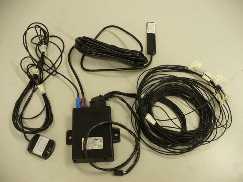
P3O96902
Apr 13, 2010Telematics Platform Accessory
Equipment Class
PCB - PCS Licensed Transmitter