P3OT2OBDBTOBD device (On Board Diagnostic device) with Bluetooth 4.0 Low Energy
META System S.p.A.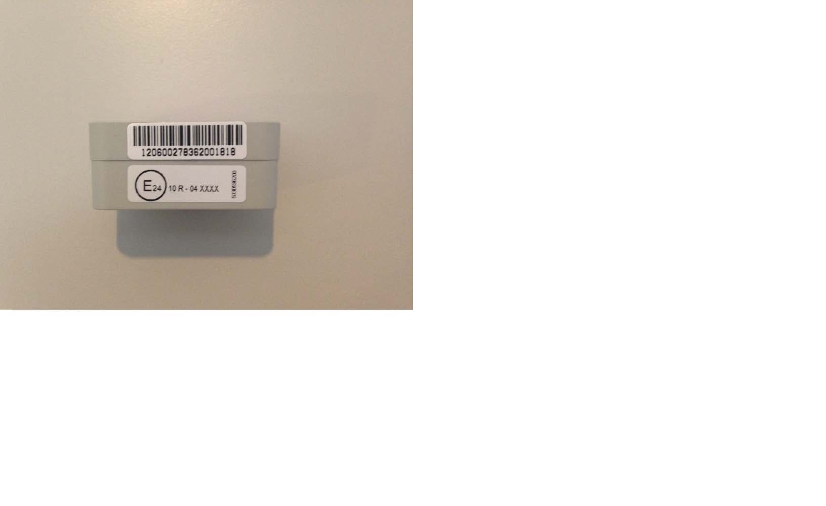
Click to zoom
Application Details
- Equipment Class
- DTS - Digital Transmission System
- Date of Grant
- Jul 13, 2015
- Application Purpose
- Original Equipment
- Date of Application
- Jul 13, 2015
- Equipment Note
- OBD device (On Board Diagnostic device) with Bluetooth 4.0 Low Energy
- Frequency Range
- 2404.00000000 - 2480.00000000
- Company
- META System S.p.A.
- Country
- Italy
Documents & Files
Document Text
Text extracted from the exhibit documents filed with the FCC. Open a document above to read the original.
Users Manual
MANUALE DI INSTALLAZIONE T. 2 IT 5040331500 COMPOSIZIONE KIT INSTALLAZIONE Alimentazione: ..................................................................................12Vdc (9V-14V) Temperatura di lavoro: .................................................................da -30°C a +80°C IP: .....................................................................................................................................40 Classifi cazione applicativa: ...........................................................vano abitacolo CARATTERISTICHE TECNICHE AVVERTENZE • TUTTE LE OPERAZIONI DI INSTALLAZIONE DEVONO ESSERE EFFETTUATE A MOTORE SPENTO. • Prima di iniziare l’installazione individuare l’ubicazione del connettore OBD utilizzando il manuale d’uso e manutenzione del veicolo. • Se devi utilizzare il connettore OBD del veicolo per altri scopi, ad esempio la manutenzione, è suffi ciente rimuovere il dispositivo dal connettore e riconnetterlo successivamente. • Attenersi esclusivamente alle operazioni indicate nel presente manuale. • Non rimuovere i sigilli garanzia e/o accedere all’interno del prodotto. • II costruttore non si assume nessuna responsabilità per danni causati a cose e/o persone determinati da una non corretta installazione del prodotto. CENTRALE TELEMATICA 1 2c2b PORTA OBD Individua il connettore OBD sul veicolo. Consulta il manuale del veicolo. In molti veicoli la porta OBD si trova: • nell’alloggiamento del freno • vicino alla scatola dei fusibili • sotto al cruscotto • nella console centrale Inserisci il dispositivo nel connet- tore OBD del veicolo. Chiudi il Secondary Lock per assicurare il dispositivo. 2a Verifi ca che il dispositivo sia interamente inserito e non si sganci. Con la presente Meta System S.p.A. dichiara che questo T.2 è conforme ai requisiti essenziali ed alle altre disposi- zioni pertinenti stabilite dalla direttiva R&TTE (1999/5). La dichiarazione di conformità può essere consultata sul sito: http://docs.metasystem.it CONFORMITÀ RIMOZIONE DEL PRODOTTO 3b Le istruzioni contenute nel seguente manuale non si riferiscono a modelli di autoveicoli specifi ci ma sono appli- cabili in via generale a tutti gli autoveicoli. Ogni eventuale contributo informativo, da parte di Meta System, su un tipo (modello) di veicolo è da ritenersi puramente indicativo. Le attività di installazione, posizionamento, fi ssag- gio del prodotto ed eventuale disinstallazione, devono essere eseguite a regola d’arte su ciascun autoveicolo. L’ inosservanza di quanto qui sopra riportato, può portare alla perdita della garanzia del dispositivo. NORME APPLICATIVE SULL’AUTOVEICOLO 3a Sblocca il Secondary Lock per rilasciare il dispositivo.Rimuovi il dispositivo.
Users Manual
T.2 INSTALLATION MANUAL EN 5040331600 KIT COMPOSITION INSTALLATION Power Supply: ..................................................................................12Vdc (9V-14V) Working temperature: ..........................................................from -30°C to +80°C IP: .....................................................................................................................................40 Application classifi cation: ...........................................passenger compartment TECHNICAL SPECIFICATIONS WARNINGS • ALL INSTALLATION OPERATIONS MUST BE CARRIED OUT WITH THE MOTOR OFF. • Before starting installation, detect the OBD port location referring to the use and maintenance manual of the vehicle. • If the OBD connector should be used for other purpose, such as maintenance, remove T2 and, after tempora- ry operation, reconnect the T2 to OBD connector. • Strictly comply with operations indicated in this manual. • Installation staff are not authorised to remove warranty seals and/or access the inside of the product. • The device must be connected to OBD port on board to the vehicle, provided with protectec power supply by means a 5 A fuse maxiumum activation current. • The manufacturer assumes no responsibility for damages caused to property and/or people, caused by the incorrect installation of the product. TELEMATIC CONTROL UNIT 1 2c2b OBD PORT By using user manual of the vehicle fi nd the OBD connector on your car. Typically OBD plug can be located: • near the breaks unit • near the fuse box • under the dashboard • in the middle console Plug the connector into the vehi- cle’s OBD. Lock the Secondary Lock to se- cure the device. 2a Check that the device is fully connected and does not unlock. Hereby, Meta System S.p.A., declares that this T.2 is in compliance with the essential requirements and other rele- vant provisions of Directive R&TTE (1999/5). The declaration of conformity may be consulted at http://docs.metasystem.it APPROVAL REMOVING THE PRODUCT 3b The instructions in this manual do not refer to specifi c vehicle models but apply to all vehicles in general. Any information provided by Meta System regarding a type (model) of vehicle is to be considered purely indicative. Installation, positioning, product securing and electrical connections, and possibly the removal, must be carried out in a workmanlike manner on each motor vehicle. The installer is obliged to and bears responsibility for ca- refully verifying the individual vehicle model on which operations are carried out. Failure to comply with that stipulated above can render the warranty of the device null and void. STANDARDS APPLICABLE TO THE VEHICLE 3a Unlock the Secondary Lock to release the device.Remove the device. Model: T2 with FCC ID.: P3OT2OBDBT This device complies with Part 15 of the FCC rules subject to the following two conditions: 1. This device may not cause harmful interference. 2. This device must accept all interference received, including interference that may cause undesired operation. This device complies with Industry Canada licence-exempt RSS standard(s). Operation is subject to the following two conditions: (1) this device may not cause interference, and (2) this device must accept any interference, including interference that may cause undesired operation of the device. For Canada only IC: 4429A - T2OBD LEGENDA : Identifi cation number of identify body. : Direct current of power supply. : Conformity mark to European certifi cation.
Users Manual
NOTICE DE MONTAGE T. 2 FR 5040331700 COMPOSITION DU KIT INSTALLATION Alimentation: ....................................................................................12Vdc (9V-14V) Plage de temperature: ..................................................................de -30°C à +80°C Indice de protection: ...............................................................................................40 Emplacement: ...............................................................................................habitacle DONNÉES TECHNIQUES ATTENTION • LE MONTAGE DE T30 DOIT ÊTRE EFFECTUÉ AVEC LE MOTEUR NON TOURNANT (ARRÊTÉ). • Avant l’installation, repérer l’emplacement de la port OBD à l’aide de la notice d’utilisation du véhicule. • Si vous devez utiliser le connecteur OBD du véhicule à d’autres fi ns, par exemple pour de la manutention, il suffi t de débrancher le dispositif du connecteur et de le rebrancher ensuite. • Se conformer strictement aux opérations indiquées dans cette instruction. • L’installateur n’est pas autorisé à retirer les bandes de garantie et/ou accéder à l’intérieur de la centrale. • Le système doit toujours être connecté à une porte OBD du véhicule qui apporte une alimentation protégée par un fusible d’une valeur-seuil de 5A. • Le fabricant n’assume aucune responsabilité pour les dommages causés aux biens et/ou personnes, par une mauvaise installation. CENTRALE 1 2c2b PORT OBD Repérez le connecteur OBD sur le véhicule. Consultez le livret de la voiture. Sur de nombreux véhicules, le port OBD se trouve: • dans l’emplacement des freins • à côté de la boîte de fusibles • sous le tableau de bord • dans la centrale de commande Branchez le dispositif au con- necteur OBD du véhicule. Fermez la Secondary Lock pour sécuriser le dispositif. 2a Vérifi ez que le dispositif soit cor- rectement activé et qu’il ne se débranche pas. Par la présente, Meta System SpA déclare que T.2 est conforme aux exigences essentielles et autres dispositions de la directive R & TTE (1999/5). La déclaration de conformité peut être consultée à http://docs.metasystem.it HOMOLOGATION DEMONTAGE DE LA CENTRALE 3b Les instructions contenues dans ce manuel ne se réfèrent pas à des modèles spécifi ques de véhicules mais s’appli- quent à tous les véhicules en général. Toute information fournie par Meta System en ce qui concerne un modèle de véhicule doit être considérée comme purement indicative. Installation, le positionnement, la fi xation du produit et des connexions électriques, et éventuellement le démon- tage, doivent être réalisées de façon professionnelle. L’installateur est obligé et porte la responsabilité de vérifi er attentivement le modèle du véhicule dans lequel les opérations sont eff ectuées. Le défaut de se conformer à des préconisations ci-dessus peut rendre la garantie de l’appareil nulle et non ave- nue. PRECONISATIONS DE MONTAGE 3a Débloquez la Secondary Lock pour pouvoir débran- cher le dispositif. Retirez le dispositif. Model: T2 with FCC ID.: P3OT2OBDBT This device complies with Part 15 of the FCC rules subject to the following two conditions: 1. This device may not cause harmful interference. 2. This device must accept all interference received, including interference that may cause undesired operation. Le present appareil est conforme aux CNR d’Industrie Canada applicables aux appareils radio exempts de licence. L’exploitation est autorisee aux deux conditions suivantes : (1) l’appareil ne doit pas produire de brouillage, et (2) l’utilisateur de l’appareil doit accepter tout brouillage radioelectrique subi, meme si le brouillage est susceptible d’en compromettre le fonctionnement. For Canada only IC: 4429A - T2OBD LEGENDA : numéro d’identifi cation de l’organisme notifi é. : courant continu de la source d’alimentation. : marque de conformité UE.
Internal Photos
T2 picture General view Bottom view Top View
Operational Description
Pagina 1 di 2 TECHNICAL SHEET Product Line – Telematics This is a confidential document only for internal use, do not disclosable Product Denomination: T. 2 Product description: The T.2 is an innovative, very small, easy to install EOBD device that provide referenced crash data. Data are locally stored in a memory and transferred on demand to a smartphone via Bluetooth. The device is plugged into the car EOBD socket, from which it takes the power supply. It even has a patented locking system to prevent accidental detachment. Product configuration: Central Unit and custom ( if needed ) packaging. Technical specification: 32bit CPU 3-axis Accelerometer (full scale 24g) High sensitivity GNSS module Bluetooth module 4.0 low energy (2404 – 2480 MHz) Antenna type ceramic antenna chip antenna loop antenna Antenna gain -1.58 dBi 32Mbit Flash memory EOBD standard connector Product size 42 x 23,5 x 19,5 mm Voltage range 12Vdc (9 – 14 Vdc) Homologation ECE-R10 – R&TTE Best Features Extremely small size Fits almost any vehicle Immediate installation Power supply from OBD port, no battery inside. Low power consumption Type of application : Installation in the EOBD port Pagina 2 di 2 TECHNICAL SHEET Product Line – Telematics This is a confidential document only for internal use, do not disclosable Type of Use: T.2 is a simply device to connect at the OBD port to collect information about trip and to transmit to a monitoring center with personal mobile device provided with Bluetooth connection. Transmission data is possible with specific App
Parts List/Tune Up Info
3020111203_C36.TXT POD T3 - Revised: venerdì, ottobre 24, 20143020111203 Revision: 0 METASYSTEM S.P.A.PROPERTY ALL RIGHTS RESERVED ART.1151-1/2/3IL TECNICO PROGETTISTA: R.ROMAGNOLIIL TECNICO DISEGNATORE: R. ROMAGNOLIDVP-S 159 REV.000 21/10/02 Bill Of Materials Oct 24,2014 9.28. 09 Page: 1 Item Quantity Reference Part ___________________________________________________ _____________________________________ ------ Componenti SMD --------------------------- --------------------------- 1 1 ANT1 21100532 00,W3000,SMD,ANTENNA-W3000 2 1 ANT2 21100531 00,W3008C,SMD,ANTENNA-W3011,,,,,2400000000 3 2 C1,C89 15000111 60,100P,SMD,0402,50V,,5%,,,C0G,AEC-Q 4 2 C2,C3 15000077 50,15P,SMD,0402,50V,,5%,,,C0G 5 7 C4,C5,C6,C7,C8,C10,C11 15000389 00,100N,SMD,0402,16V,,10%,,,X7R,AEC-Q 6 14 C9,C36,C37,C38,C39,C40, 15000227 00,100N,SMD,0402,16V,,,,,X7R C41,C42,C44,C45,C46,C47 C48,C49 7 7 C12,C13,C14,C15,C16,C17, 15000435 00,2U2,SMD,0402,6V3,,10%,,,X5R C18 8 2 C19,C20 15000453 00,100N,SMD,0402,50V,,+/-10%,,,-40/+85°C 9 1 C25 15000154 00,1N,SMD,0402,50V,,10%,,,X7R 10 1 C26 15000249 00,220N,SMD,0402,10V,,10%,,,X5R 11 1 C27 15000443 00,10U,SMD,0402,4V,,,,,X5R 12 2 C28,C29 15000405 00,120P,SMD,0402,50V,,5%,,,C0G 13 2 C30,C31 15000454 00,22U,SMD,0805_C_DX,,,+/-10%,,,-40/+85°C 14 1 C32 15000090 00,33P,SMD,0402,50V,,,,,C0G 15 1 C35 15000052 50,3P9,SMD,0402,50V,,+/-0.1PF,,,C0G 16 2 C54,C55 15000079 00,18P,SMD,0402,50V,,5%,,,C0G 17 8 C56,C57,C58,C59,C60,C62, 15000269 00,1U,SMD,0402,10V,,10%,,,X5R C63,C64 18 1 C65 15000455 00,22U,SMD,0603,6V3,,+/-10%,,,-40/+85°C 19 1 C66 15000194 00,10N,SMD,0402,25V,,,,,X7R 20 1 C68 15000069 00,8P2,SMD,0402,50V,,,,,C0G 21 10 C71,C72,C73,C77,C78,C79, 15000111 00,100P,SMD,0402,50V,,5%,,,C0G C80,C81,C82,C83 22 1 C84 15000263 00,470N,SMD,0402,6V3,,10%,,,X5R 23 1 D1 15200077 00,100V,SMD,SOD-523,100V,,,200MA 24 2 DZ1,DZ2 15200030 00,BZX585-16V,SMD,SOD-523,16V,1/5W,5% 25 2 L1,L2 16100149 00,5N6H,SMD,0402 1agina p 3020111203_C36.TXT 26 1 L3 11500130 00,BLM15HG601,SMD,0402 27 1 L8 16100059 00,1UH,SMD,0805_C_DX,,,20% 28 1 L9 16100178 00,5N8H,SMD,0402,,,+/-0.1 29 1 L10 16100117 00,18NH,SMD,0402,,,,,,,2,1GH 30 1 L11 16100121 00,4U7H,SMD,IND-SMD-LQM2HP,,,20% 31 1 L12 16100148 00,6N2H,SMD,0402 32 1 L13 16100023 00,10NH,SMD,0402 33 1 L14 16100177 00,7N3H,SMD,0402,,,2% 34 1 L15 16100193 00,2N7H,SMD,0402 35 1 Q1 15900186 00,BC857XMB,SMD,SOT-883,45V,,,100MA 36 2 Q7,Q8 15900187 00,PMZB350UPE,SMD,SOT-883,20V 37 1 QZ1 11500146 00,32KHZ,SMD,RISUON-Q-2012 POD T3 - Revised: venerdì, ottobre 24, 2014 3020111203 Revision: 0 METASYSTEM S.P.A.PROPERTY ALL RIGHTS RESERVED ART.1151-1/2/3IL TECNICO PROGETTISTA: R.ROMAGNOLIIL TECNICO DISEGNATORE: R. ROMAGNOLIDVP-S 159 REV.000 21/10/02 Bill Of Materials Oct 24,2014 9.28. 09 Page: 2 Item Quantity Reference Part ___________________________________________________ _____________________________________ 38 2 R1,R2 15500137 00,1K,SMD,0402,,1/16W,5% 39 1 R3 15600384 00,220K,SMD,0402,,1/16W,1% 40 1 R4 15600406 00,47K,SMD,0402,,1/16W,1% 41 3 R5,R6,R7 15500092 00,100,SMD,0402,,1/16W,5% 42 4 R9,R20,R22,R23 15500242 00,100K,SMD,0402,,1/16W,5% 43 1 R12 15600423 00,56K,SMD,0402,,1/16W,1% 44 1 R15 15600393 00,100K,SMD,0402,,1/16W,1% 45 1 R18 15500287 00,1M,SMD,0402,,1/16W,5% 46 1 R24 15600403 00,120K,SMD,0402,,1/16W,1% 47 1 R25 15500136 00,1K,SMD,0603,,1/10W,5% 48 1 R26 15600396 00,330K,SMD,0402,,1/16W,1% 49 2 R27,R38 15500152 00,2K2,SMD,0402,,1/16W,5% 50 6 R28,R29,R31,R32,R33,R34 15500190 00,10K,SMD,0402,,1/16W,5% 51 1 R35 15500251 00,150K,SMD,0402,,1/16W,5% 52 1 RK1 12000035 00,3R3,SMD,0603,16V,,20%,6A,,-10/+65°C 53 1 RN2 15700032 00,10K,SMD,RETE-RES-4-0402,,,5% 54 3 RN3,RN4,RN5 15700030 00,2K2,SMD,RETE-RES-4-0402,,,5% 55 1 U1 15900144 00,SI3459BD,SMD,TSOP-6 56 1 U3 15400848 00,TPS62160,SMD,S-PWSON-N8-2X2,3V-17V,,,1A,,-40/125 °C 57 1 U4 15400727 00,STA8088FG,SMD,VFQFPN56-EP,3V3,,,,,-40/+85C 58 1 U5 15400762 00,MX25L8006E,SMD,USON-8LEAD,2V7/3V6,,,,,-40/+85C 2agina p 3020111203_C36.TXT 59 1 U6 15400671 00,K3DHTR,SMD,LGA-16-3X3,1V71/3V6,,,,,-40/+85C 60 1 U7 15400800 00,STM32F303CC6,SMD,LQFP-48,,,,,,-40/+85°C 61 1 U8 15400736 00,ALM-3012,SMD,MCOB-8 62 2 U9,U10 11500147 00,1588MHZ,SMD,QCS-5P,,,,,1588MHZ 63 1 U11 15400798 00,LP5900TL-1V8,SMD,DSBGA4,,,,,,-40/125°C 64 1 U12 15400799 00,CC2541,SMD,PVQFN-40,,,,,,-40/+85°C 65 1 U13 11500137 00,26MHZ,SMD,Q-TCXO-2016,,,,,26MHZ 66 1 U16 15400879 00,BAL-CC25-01D3,SMD,DSBGA4-ST,,,,,,-40/125°C 67 1 X1 11500145 00,OSC32MHZ,SMD,Q-TCXO-2016,,,,,32MHZ Numero totale Componenti SMD: 132 ------ Componenti Tradizionali ------------------ --------------------------- 3agina p
RF Exposure Info
FCC ID: P3O T2OBDBT Prediction of MPE limit at a given distance Equation from page 18 of OET Bulletin 65, Edition 97-01 where:S = power density P = power input to the antenna G = power gain of the antenna in the direction of interest relative to an isotropic radiator R = distance to the center of radiation of the antenna Maximum peak output power at antenna input terminal:-7,27(dBm) Maximum peak output power at antenna input terminal:0,187(mW) Antenna gain(typical): -1,58(dBi) Maximum antenna gain: 0,7(numeric) Prediction distance:20(cm) Prediction frequency:2404(MHz) MPE limit for uncontrolled exposure at prediction frequency:1(mW/cm 2 ) Power density at prediction frequency:0,0000259(mW/cm 2 ) Maximum allowable antenna gain:44,3(dBi) Margin of Compliance:45,9 2 4R PG S π =
Test Report
This Test Report, when bearing the Nemko name and logo is only valid when issued by a Nemko laboratory, or by a laboratory having special agreement with Nemko. Report Reference ID: 274225-1TRFWL Test specification: Title 47 – Telecommunication Chapter I – Federal Communication Commission Subchapter A – General Part 15 – Radio Frequency Devices Subpart C – Unintentional Radiators §15.247 Operation within the bands 902-928 MHz, 2400-2483.5 MHz, 5725-5875 MHZ. Applicant: Meta System S.p.A. Via Galimberti, 5, – 42124- Reggio Emilia (RE) – Italy Apparatus: EOBD device Model: T.2 FCC ID: P3O T2OBDBT Testing laboratory: Nemko Italy Spa Via del Carroccio, 4 20853 Biassono (MB) – Italy Telephone: +39 039 2201201 Facsimile: +39 039 2201221 Name and title Date Tested by: G. Curioni, Wireless/EMC Specialist 2015-05-22 Reviewed by: P. Barbieri, Wireless/EMC Specialist 2015-05-22 © Nemko Spa, 20853 Biassono (MB) - Italy. All rights reserved. This publication may be reproduced in whole for non-commercial purposes as long as Nemko Spa is acknowledged as copyright owner and source of the material. Nemko Spa takes no responsibility for and will not assume liability for damages resulting from the reader's interpretation of the reproduced material due to its placement and context. Nemko Spa accepts no responsibility for damages, if any, suffered by any third party as a result of decisions made or actions based on this report. This test report may not be partially reproduced, except with the prior written permission of Nemko Spa. The test report merely corresponds to the test sample. The phase of sampling / collection of equipment under test is carried out by the customer. Product: EOBD Report reference ID: 274225-1TRFWL Page 2 of 59 Table of contents Section 1: Report summary ........................................................................................................................................... 3 1.1 Test specification .......................................................................................................................................... 3 1.2 Statement of compliance ............................................................................................................................... 3 1.3 Exclusions ..................................................................................................................................................... 3 1.4 Registration number ...................................................................................................................................... 3 1.5 Test report revision history ............................................................................................................................ 3 1.6 Limits of responsibility ................................................................................................................................... 3 Section 2: Summary of test results ............................................................................................................................... 4 2.1 FCC Part 15 Subpart C – Intentional Radiators, test results ......................................................................... 4 Section 3: Equipment under test (EUT) and application details ................................................................................ 5 3.1 Applicant details ............................................................................................................................................ 5 3.2 Modular equipment........................................................................................................................................ 5 3.3 Product details .............................................................................................................................................. 5 3.4 Application purpose ....................................................................................................................................... 5 3.5 Composite/related equipment ....................................................................................................................... 5 3.6 Sample information ....................................................................................................................................... 6 3.7 EUT technical specifications ......................................................................................................................... 6 3.8 Operation of the EUT during testing .............................................................................................................. 6 3.9 EUT setup diagram ....................................................................................................................................... 6 Section 4: Engineering considerations ........................................................................................................................ 7 4.1 Modifications incorporated in the EUT .......................................................................................................... 7 4.2 Deviations from laboratory tests procedures ................................................................................................. 7 4.3 Technical judgment ....................................................................................................................................... 7 Section 5: Test conditions ............................................................................................................................................. 8 5.1 Power source and ambient temperatures ..................................................................................................... 8 Section 6: Measurement uncertainty ............................................................................................................................ 9 Section 7: Test equipment .....................................................................................…
Text truncated - open the document above for the full version.
Test Setup Photos
274225_Setup_Photos Page 1 of 1 EUT setup photos
Contact Information
Applicant
Giorgio Maldini(Product Homologation Manager)
Test Firm
Nemko SpARalph Spanevello
Technical Specifications
| # | Rule Parts | Frequency Range | Power Output |
|---|---|---|---|
| 1 | 15C | 2.40 GHz - 2.48 GHz | 187.50 µW |
Other Applications from META System S.p.A.
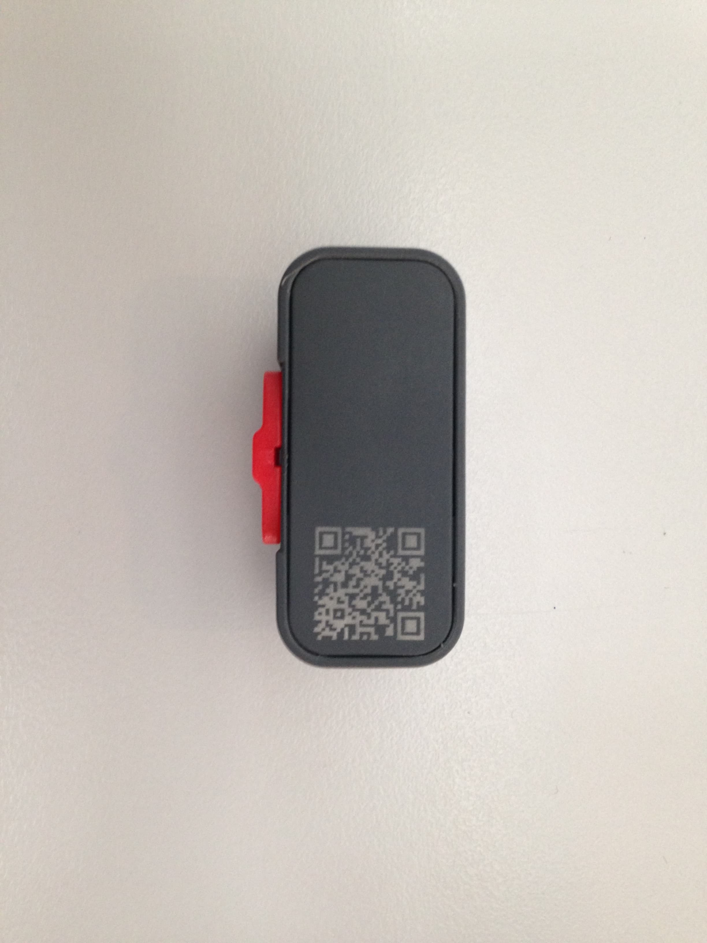
P3OT2PLUS
Nov 24, 2015OBD device (On Board Diagnostic device) with Bluetooth 4.0 low energy
Equipment Class
DTS - Digital Transmission System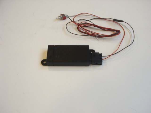
P3O001692
Jun 07, 2011Microwave Sensor for intrusion and movement detection
Equipment Class
DXX - Part 15 Low Power Communication Device Transmitter
P3O98400
Nov 15, 2010TXBMWMR
Equipment Class
DSC - Part 15 Security/Remote Control Transmitter
P3O97802
Jun 27, 2010Telematic Tracking System
Equipment Class
PCB - PCS Licensed Transmitter
P3O96902
Apr 13, 2010Telematics Platform Accessory
Equipment Class
PCB - PCS Licensed Transmitter