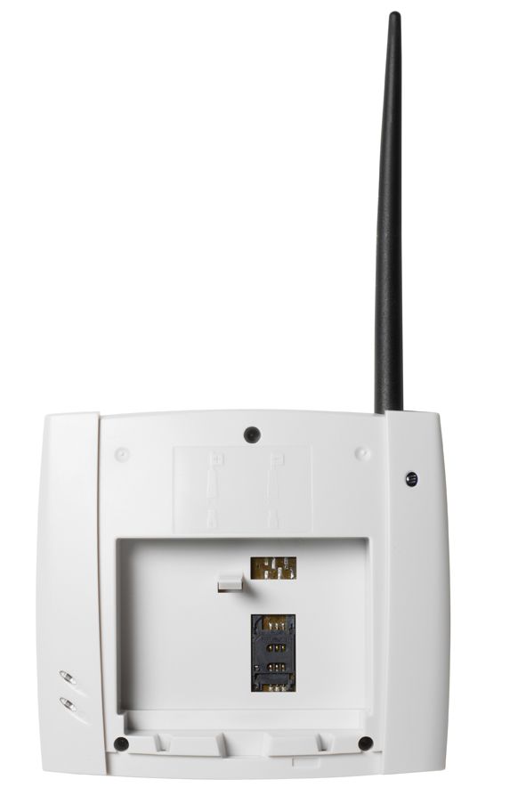
P5L-FWTG32Fixed Wireless Terminal
Ericsson AB
Click to zoom
Application Details
- Equipment Class
- PCB - PCS Licensed Transmitter
- Date of Grant
- Dec 06, 2006
- Application Purpose
- Original Equipment
- Date of Application
- Dec 06, 2006
- Equipment Note
- Fixed Wireless Terminal
- Frequency Range
- 1850.20000000 - 1909.80000000
- Company
- Ericsson AB
- Country
- Sweden
Documents & Files
Document Text
Text extracted from the exhibit documents filed with the FCC. Open a document above to read the original.
Users Manual
Ericsson G32 / G36 Fixed Wireless Terminal for GSM/EDGE Mobile Networks User Guide EN/LZT 151 235 R1D © Ericsson AB 2006 — All Rights Reserved Table of Contents Fixed Wireless Terminal: G32 and G36 models 3 Table of Contents Table of Contents..........................................3 Welcome.......................................................4 Fixed Wireless Terminal.................................4 Installation.....................................................4 Connecting Devices to the FWT ....................4 Advanced Features.......................................4 PC Data Configurations.................................4 Web-based Configuration..............................4 Troubleshooting............................................4 Technical Data..............................................4 Accessories ..................................................4 Product Care and Safety...............................4 Warranty.......................................................4 Glossary........................................................4 Index.............................................................4 Welcome 4 Fixed Wireless Terminal: G32 and G36 models Welcome Welcome to the User Guide for the G32 / G36 Fixed Wireless Terminal. Important information: Some of the services described in this guide might not be supported by all networks. Please, contact your network operator for information on different network services operational in your GSM network. The latest version of this user guide can be downloaded from: http://www.ericsson.com/enterprise/library/manual.shtml Disposal of the product Your product should not be placed in municipal waste. Please check local regulations for disposal of electronic products. Welcome Fixed Wireless Terminal: G32 and G36 models 5 Copyright No part of this document may be reproduced without the written permission of the copyright owner. The contents of this document are subject to revision without notice due to continued progress in methodology, design and manufacturing. Ericsson shall have no liability for any error or damage of any kind resulting from the use of this document. Warranty ERICSSON MAKES NO WARRANTY OF ANY KIND WITH REGARD TO THIS MATERIAL, INCLUDING, BUT NOT LIMITED TO, THE IMPLIED WARRANTIES OF MERCHANTABILITY AND FITNESS FOR A PARTICULAR PURPOSE. Ericsson shall not be liable for errors contained herein nor for incidental or consequential damages in connection with the furnishing, performance or use of this material. Declaration of Conformity Hereby, Ericsson Enterprise AB declares that this product is in conformity with the requirements and other relevant provisions of the European R&TTE directive 1999/5/EC. Details to be found at: http://ericsson.com/sdoc. FCC Statement Before a wireless terminal is available for sale to the public, it must be tested and certified to the FCC that it does not exceed the limit established by the government adopted requirement for safe exposure. This device complies with CFR17 Part 15 and Part 24 of the FCC rules. Operation is subject to the following two conditions: (1) This device may not cause harmful interference, and (2) this device must accept any interference received, including interference that may cause undesired operation. Fixed Wireless Terminal 6 Fixed Wireless Terminal: G32 and G36 models Fixed Wireless Terminal Product Description The FWT is a flexible and cost-effective solution for connection to the wireless GSM network when there is no fixed line infrastructure or if you need additional telephone lines. The G36 can also be connected to a PBX so you can benefit from the Least Cost Routing (LCR) capabilities offered by most PBX vendors to optimize your costs by routing outgoing calls to mobile phones through the GSM network. The FWT allows automatic network searching between GSM 850/1900 or GSM 900/1800 frequencies, ensuring world wide coverage in the GSM networks. The FWT features the latest technology, which makes it perfect for everyday communication: • Available in 2 dual dual-band GSM models (GSM 850/1900 or GSM 900/1800). • Telephone line providing high quality speech, G3 fax and up to V.90 data transmission. • EDGE (Enhanced Data Rates for GSM Evolution) is a 3G technology that delivers broadband-like speeds to GSM devices. • GPRS (General Packet Radio Service), which keeps you always connected and facilitates rapid transmission of data (ideal for e- mail and Internet browsing). • Embedded modem available over the USB port. • Battery back-up (optional). • PBX connectivity (only on the G36 model). Fixed Wireless Terminal Fixed Wireless Terminal: G32 and G36 models 7 Supplied Parts After unpacking, please check that the following parts and list of components are included: List of Components 1. FWT unit 2. Antenna 3. 4 x mounting screws 4. Power cable (USA, UK, EU or AUS) 5. AC/DC adapter 6. Wall mount bracket 7. Telephone cable 8. Quick Guide and User Guide manuals 9. CD with USB driver Fixed Wireless Terminal 8 Fixed Wireless Terminal: G32 and G36 models External Connector and Indicators Installation Fixed Wireless Terminal: G32 and G36 models 9 Installation SIM Card Your network operator provides you with a SIM (Subscriber Identity Module) card. The SIM card contains information about your telephone number and the services included in your subscription. Preparing Your FWT You need to follow these steps before you install the FWT on the wall and finalize all connections. Warning: The FWT should be switched off before inserting or removing your SIM card or connecting any devices to the FWT. Assembly 1. Connect the antenna. Installation 10 Fixed Wireless Terminal: G32 and G36 models 2. Remove the front cover, by pressing down and pushing the small tab that is in the center of the bottom part of the FWT. Open the SIM Card holder and insert the SIM Card. 3. Close the SIM Card holder, placing it horizontally and securing it with the sliding part of the holder. 4. Install…
Text truncated - open the document above for the full version.
Cover Letter(s)
260 Surrey Avenue +27 11 293 0500 Main Ferndale, Randburg, 2194 +27 11 293 0555 Fax Box 412, Pinegowrie, 1993/06651/07 2123, South Africa www.flextronics.com 24 March 2006 Telecommunication Certification Body RFI Global Services Ltd. Pavilion A Ashwood Park Basingstoke Hampshire RG23 8BG United Kingdom Subject: Certification Application FCC ID: P5L-FWT32 It is requested that the following information is to be held confidential on behalf of Flextronics South Africa (Pty) Ltd. FCC Rules Part 0.459 refers. Description No of Files No of pages Reason for Confidentiality Block Diagrams 1 files 3 pages Proprietary design Disclosure of this information will cause substantial competitive harm. Electrical Schematics 1 file 8 pages Proprietary design Disclosure of this information will cause substantial competitive harm. Mechanical Drawings 2 files 1 page per file Proprietary design Disclosure of this information will cause substantial competitive harm. Parts List 1 files 3 pages per file Proprietary design Disclosure of this information will cause substantial competitive harm. Yours sincerely Bernd Kleyenstüber Senior Engineering Manager Directors: ID Robertson MW Robson NA Solanki
Cover Letter(s)
Federal Communications Commission 445 12th Street, SW Washington, DC 20554 18 October 2007 Request for Grant Change FCC ID: P5L-FWTG32 Dear Sirs, Can you please change the above Grant which lists an incorrect frequency range of 842.2 - 848.8MHz. This is a typographical error. Please change the Grant to show 824.2 - 848.8MHz. The technical content of the filing is unaffected as the testing was carried out in accordance with the 824.2 - 848.8MHz frequency range. Thank you. John Bellairs Senior Engineer and TCB RFI Global Services Ltd. Basingstoke, England Direct Tel: +44 (0) 1256 855473 Fax: +44 (0) 1256 312001 E-mail: [email protected] Web Site: http://www.rfi-global.com
ID Label/Location Info
Limited Internal MARKING DRAWING 1 (2) Prepared (also subject responsible if other) No. EBC/FLEXSA (Titus Mavuso) 151 86-KRC 161 084/0 Uen Approved Checked Date Rev Reference EBC/FLEXSA (Bernd Kleyenstuber) 2006-07-26 D Type Label - KRC 161 084-089 Note 1 Note 2 Note 3 Note 4 Note 5 Note 6 Note 7 Note 8 Note 9 Note 10 Notes: 1. Ericsson logotype according to 190 89-EN/LZT 108 901 2. CE 0889 logotype according to 1424-SVF 930 52 Notified body number (0889), according to the TTE Annex III certificate for the production plant. UL Symbol according to UL1950. Overall diameter of the UL mark is 4mm. Registered trademark® letter: “Helvetica Condensed Medium”. Rest of the lettering: ”Helvetica Condensed Black” 3. The WEEE symbol of the crossed out wheeled bin according to EN 61429 Amd. Marking of electrical and electronic equipment in accordance with article 11(2) of Directive 202/96/EC (WEEE). 4. TYPE: FWTG32 G H I J G = R-state identification of the software (CXP) module H = R-state identification of the hardware I = PCBA structure identification (ROA) J = R-state identification of the PCBA (ROA) Note: G, H, I and J fields according to 1/151 86-KRC 161 084 Limited Internal MARKING DRAWING 2 (2) Prepared (also subject responsible if other) No. EBC/FLEXSA (Titus Mavuso) 151 86-KRC 161 084/0 Uen Approved Checked Date Rev Reference EBC/FLEXSA (Bernd Kleyenstuber) 2006-07-26 D 5. FCC certification: FCC ID: P5L-FWTG32 6. Industry Canada: IC: 2871-FWTG32 7. Product number with revision state: KRC xxx xxx Rzz 8. Serial number xxxxxxxxxx 9. IMEI number: xxxxxx-xx-xxxxxx-x 10. Country of manufacture: Made in xxxxx Date of production: yyyy = year, ww = week All printing will be readable and permanent. Text should be centred. Material used for label marking is defined in product specification 1301-SVF 904 04 Printing dimensions: • Type size: min 1.1mm • Line spacing: min 1.0mm • Ericsson logo: min 2.25mm • CE symbol: min 5.0mm • Notified body (0889): same size as CE symbol
Operational Description
221 02-FGB 101 350 Uen Rev C G3x Series Fixed Wireless Terminals for GSM/EDGE Mobile Networks Technical Product Description The product description for the Fixed Wireless Access Terminals G3x Series offers a complete description of the product from a hardware and software perspective. Applications such as fixed line replacement and PBX Least Cost Routing for businesses are also briefly described. G3x Series 221 02-FGB 101 350 Uen Rev C ” Ericsson Enterprise AB 2 (18) Contents 1 G3x Series Overview ............................................................................3 2 Features ................................................................................................4 3 Technical Specifications......................................................................7 4 Standard Product Kit..........................................................................12 5 Accessories ........................................................................................12 6 Spare Parts .........................................................................................14 7 Security ...............................................................................................15 8 Applications........................................................................................16 9 Acronyms............................................................................................18 G3x Series 221 02-FGB 101 350 Uen Rev C ” Ericsson Enterprise AB 3 (18) 1 G3x Series Overview The Fixed Wireless Access is a cost efficient solution for providing fixed voice, data and fax services to areas with no fixed infrastructure in a cost efficient way utilizing an existing GSM infrastructure. Data connectivity is provided either through circuit switched or packet switched GPRS/EDGE technology, offering an ideal solution for Internet access. Additionally the terminal can be connected to a PBX for LCR of outgoing mobile calls enabling increased traffic for the operator and cost savings for businesses. The G3x fixed wireless terminal series has the following main characteristics: ∑ Four GSM bands available in two different models 850/1900 & 900/1800 ∑ EDGE Multislot class 10 (4+1) alt (3+2) or GPRS Multislot class 10 (4+1) alt (3+2) packet switched data transmission, comparable to PSTN modem connections with “always-on” connectivity?? ∑ Circuit switched data 9600 bps ∑ GSM V.42bis data compression ∑ Integrated V.90 analog modem ∑ Single Telephony line interface with standard connection for voice, fax and modem that can facilitate up to 3 devices in parallel, though only 1 device can be used at a time. ∑ Fax and data transmission using USB connection ∑ The terminal can be powered from AC mains, DC power source or an internal battery ∑ Integrated design for high quality and performance ∑ PBX connectivity via analog trunk ∑ Remote Management capability The G3x fixed wireless terminal series consist of the following models: ∑ G30 – For voice only ∑ G31 – For data only ∑ G32 – Voice, data and fax ∑ G35 – For PBXs and least cost routing ∑ G35 – For PBXs, least cost routing, data and fax G3x Series 221 02-FGB 101 350 Uen Rev C ” Ericsson Enterprise AB 4 (18) 2 Features G30 G31 G32 G35 G36 Voice Yes - Yes Yes Yes Data - Yes Yes - Yes SMS - Yes Yes - Yes Fax - PC fax Yes - Yes PBX - - - Yes Yes GSM suppl. services Yes - Yes Yes Yes Voice mail alert Yes - Yes Yes Yes Phone Book Yes - Yes Yes Yes Pre-paid services Yes Yes Yes Yes Yes Operator Name Yes - Yes Yes Yes DTMF - DTMF DTMF DTMF AT comm. AT comm. AT comm. AT comm. AT comm. Terminal administration - Web I/F Web I/F - Web I/F Remote Management Yes Yes Yes Yes Yes The table above is a summary of what features are available in each terminal. The features are described below. 2.1 Voice Standard voice service is provided by the RJ-11 connector by using a standard analogue phone. 2.2 Data Data connectivity is provided via the RJ-11 connector or the USB connector. Please note that the maximum transmission speed using the 2 wire line RJ-11 connector is limited by the V.90 analog modem in the PC, normally 56 kbps. 2.3 SMS The Terminal can send SMS:s by connecting a PC to the USB port. The PC needs to have a 3 rd party application. G3x Series 221 02-FGB 101 350 Uen Rev C ” Ericsson Enterprise AB 5 (18) 2.4 Fax The data capable models of the Terminal can send faxes either through the 2-wire interface or by connecting a PC to the USB port. The PC needs to have a 3 rd party application. 2.5 PBX This feature allows connection to a PBX. It supports polarity reversal (only on G35 and G36) and loop-break. 2.6 GSM Supplementary Services The Terminal supports GSM supplementary services, in order to use the services; the operator network must support them. Offered supplementary services can only be used with a DTMF telephone connected to the Terminal. ∑ Call Waiting ∑ Call Divert (Forward) ∑ Call Barring ∑ Call Hold ∑ Call Transfer ∑ Multiparty call ∑ Dual numbering The Terminal can handle alternate line service handle (2 voice lines) with a dual number SIM card. Alternative service handling can be managed from the telephone connected to the Terminal. You will receive all the incoming calls addressed to any of your numbers independently of the selected line but your outgoing calls will be charged to the line that you have selected (1 or 2) 2.7 Voice Mail alert The answering service of the GSM network (operator dependant) allows callers to leave a voice message when you cannot answer your calls. The Terminal gives a special acoustic indication to indicate the presence of voice mail. 2.8 Phone Book Telephone numbers can be stored for abbreviated dialing in either the SIM card memory or the Terminal memory (up to 99 numbers in each). G3x Series 221 02-FGB 101 350 Uen Rev C ” Ericsson Enterprise AB 6 (18) 2.9 Pre-paid services The operator can offer the Terminal together with a pre-paid GSM service, which is usually not supported by fixed networks. 2.10 Operator Name An …
Text truncated - open the document above for the full version.
Operational Description
Key features • Single-chip RF transceiver in small HVQFN40 package (6 x 6 x 0.85 mm) with quad-band capability: 850, 900, 1800 and 1900 MHz • GSM/GPRS Class 12 and full EDGE Rx & Tx Class 12 operation • Low-IF receiver with low noise, wide dynamic range and more than 68 dB gain control • Direct up-conversion transmitter with excellent noise capabilities (−163 dBc/Hz @ 20 MHz offset) eliminating the need for a SAW fi lter before the power amplifi er (PA) • Fully-integrated fractional-N synthesizer with AFC control option, fully-differential design to minimize crosstalk and spurs, and all supply regulators, the VCO and reference oscillator are on-chip • Functions from a 2.4–3.0 V supply • Outputs to control front-end switches (pin diodes) and 3-wire serial bus interface • Compatible with Philips’ 3G (WCDMA) RF chipset, optimized for Philips’ 2G/2.5G baseband and PA, and provides the RF core of Philips’ 2.5G system solutions. Semiconductors The UAA3537 single-chip transceiver supports GSM/GPRS and the full EDGE (Rx + Tx) standard. Only 36 mm 2 in size, it can operate in the 4 GSM/DCS/PCS bands (850, 900, 1800 and 1900 MHz) used worldwide. Combining a high integration level with high performance, this versatile radio is suitable for many applications - from low cost/highly-integrated handsets up to highly-featured terminals/PDAs. UAA3537 GSM/EDGE transceiver General information The UAA3537 is a complete RF solution for developing cost- and performance-optimized 2G, 2.5G/EDGE handsets and terminals. The IC is a 3rd generation Philips Semiconductors GSM RF transceiver, using Philips’ pioneering Near-Zero IF (N-ZIF) architecture in the receiver. Now recognized (and copied) by many, this is the most cost-effective and performance-capable receiver architecture. The transmitter architecture uses a new, direct up-conversion approach. Leveraging the advantages of Philips Semiconductors’ advanced BiCMOS process (QUBiC 4), this provides the necessary transmit noise performance without using any transmit SAW fi lters. And it’s this architecture that makes the transmitter not only compliant with EDGE, but also very cost-effective. The IC’s high level of integration has also made it cost-effective to have four receiver Low Noise Amplifi ers (LNAs) on-chip. Though suitable for quad-band applications, not all have to be used. LNAs are simply enabled or disabled by programming, making it easy for manufacturers to have compatible designs between different platforms: dual band, triple band or quad band. For example, triple band platforms can use this fl exibility to enable any of the following confi gurations: • 850 + 1800 + 1900 or 900 + 1800 + 1900 MHz • 850 + 900 + 1800 or 850 + 900 + 1900 MHz. The UAA3537 is optimized to work with Philips Semiconductors’ baseband and power amplifi er (PA) products. Full system functionality has been successfully proven — the UAA3537 is essentially the radio in our widely-used 2.5G system solution. What’s more, the IC can be combined with our 3G (UMTS) RF chipset in multimode phones, where it also delivers the reference clock for cross-mode synchronization and optimization. Quad-band, one-chip RF transceiver for Class 12 GSM/GPRS/EDGE (Rx + Tx) In summary, the UAA3537 offers a unique feature set in the mobile communications market by combining the following capabilities: • a very high integration level • complete fl exibility for many application/phone designs • a low bill-of-materials for all system developments - from dual band to quad band, and from GSM up to full EDGE. Key blocks in detail Receiver The receiver consists of the RF receive front-end and the IF section. The front-end amplifi es the GSM (869–894 or 925–960 MHz), DCS (1805–1880 MHz) or PCS (1930–1990 MHz) antenna signal and down-converts the chosen channel to a low IF of 100 kHz, providing more than 35 dB image suppression. Of the four on-chip LNAs, two are connected to the same package outputs - selectivity is provided by an on-chip low-pass fi lter. Channel selectivity is provided by a high-performance integrated band-pass fi lter. The IF section then amplifi es the selected channel, performs gain control to tune the output level to the required value and rejects DC. For the latter, an active high-pass circuit can be programmed to either operate continuously or keep an acquired DC offset correction during the burst. Transmitter The transmitter is fully differential and uses a direct, up-conversion architecture. It consists of a single-sideband power up-mixer. Gain is set over 40 dB via the 3 wire serial programming bus. The fully-integrated VCO and the power mixer provide local oscillator (LO) suppression, quadrature phase-error correction, quadrature amplitude balance and a low noise-fl oor to meet system specifi cations without a SAW fi lter. IC control The circuit can be powered-up into four different modes - Rx, Tx, Syn or Ref mode - depending on the particular supply voltages applied, the logical level at the Ctrl pin, and the 3-wire serial bus programming. In Rx or Tx mode, all sections required for receiving/transmitting are turned on. The Syn mode is used to power-up the Synthesizer and the VCO prior to the Rx or Tx mode. In the Syn mode, some internal LO buffers are also powered-up so that VCO-pulling is minimized when switching on the receiver or transmitter. The Reference Oscillator (Ref mode) is turned on by applying Semiconductors UAA3537 GSM/EDGE transceiver Quad-band, one-chip RF transceiver for Class 12 GSM/GPRS/EDGE (Rx + Tx) the appropriate supply voltage (see below). Additionally, the band is selected by programming the IC via the 3-wire serial bus, enabling the required LNAs. Reference oscillator The heart of the reference oscillator (26 MHz) is an integrated amplifi er - externally only a quartz crystal and few passive components are needed. After buffering, a reference clock of 26 MHz is supplied to other parts of the system through the pin CLKOUT (see Fig.1). An internal supply volt…
Text truncated - open the document above for the full version.
RF Exposure Info
ERIFWT102TN1420 Technical Note Page 1 of 3 Issued Version 1.00.00 Confidential Copyright © 2005-2006 – Flextronics International. All rights reserved. Trademark Notice: Product or corporate names may be trademarks or registered trademarks, and are only used for identification and explanation, without intent to infringe. This document may not be reproduced in whole or in part in any form, without prior written permission from Ericsson. Permission to copy granted to Flextronics International. MPE Calculation for Project Name: Ericsson Fixed Wireless Terminal Project Code: ERIFWT102 Product: G3x FWT Product Series Prepared for: Ericsson Author(s): Alan van Gerve Last saved: 3-Jul-06 Design Center: Flextronics SA www.flextronics.co.za ERIFWT102TN1420 Technical Note Page 2 of 3 Issued Version 1.00.00 Confidential Copyright © 2005-2006 – Flextronics International. All rights reserved. Trademark Notice: Product or corporate names may be trademarks or registered trademarks, and are only used for identification and explanation, without intent to infringe. This document may not be reproduced in whole or in part in any form, without prior written permission from Ericsson. Permission to copy granted to Flextronics International. 1. MPE CALCULATION FOR THE FWT G30 PRODUCT SERIES 1.1 Introduction The FCC requires that the calculated MPE be equal to or less than the limits for general population/uncontrolled exposure as detailed in Part 1.1310 of the FCC regulations at a distance of 20cm from the device to the body of the user. The equation for the calculation is given in OET Bulletin 65, page 19 as: S = EIRP / 4 π R 2 Where S = Power density EIRP = Effective Isotropically Radiated Power R = distance to the centre of the radiation of the antenna 1.2 For 850 MHz Values S = 0.566 mW/cm 2 (f/300) for general population uncontrolled exposure (FCC Part 1.1310 Radiofrequency radiation exposure limits) ERP = 27.4 dBm (550 mW) ERP x 1.64 = EIRP R = 20 cm Calculation S = 550 x 1.64 / 12.56 x (20) 2 S = 820 / 12.56 x (20) 2 S = 820 / 5024 S = 0.163 mW 2 ERIFWT102TN1420 Technical Note Page 3 of 3 Issued Version 1.00.00 Confidential Copyright © 2005-2006 – Flextronics International. All rights reserved. Trademark Notice: Product or corporate names may be trademarks or registered trademarks, and are only used for identification and explanation, without intent to infringe. This document may not be reproduced in whole or in part in any form, without prior written permission from Ericsson. Permission to copy granted to Flextronics International. 1.3 For 1900 MHz Values S = 1 mW/cm 2 for general population uncontrolled exposure (FCC Part 1.1310 Radiofrequency radiation exposure limits) EIRP = 29.6 dBm (912 mW) R = 20 cm Calculation S = 912 / 12.56 x (20) 2 S = 912 / 5024 S = 0.182 mW 2 1.4 Conclusion The MPE values of the FWT G30 Product Series at 20 cm meet the RF exposure limits.
Test Report
TEST REPORT FROM RFI GLOBAL SERVICES LTD Test of: Ericsson Enterprise AB Fixed Wireless Terminal - G32a To: FCC Part 22: 2005 (Subpart H) and FCC Part 24: 2005 (Subpart E) Test Report Serial No: RFI/RPTE4/RP48122JD03A Supersedes Test Report Serial No: RFI/RPTE3/RP48122JD03A This Test Report Is Issued Under The Authority Of Andrew Brown, Operations Manager: Tested By: Steven Wong Checked By: Tony Henriques Report Copy No: PDF01 Issue Date: 24 October 2006 Test Dates: 28 April to 12 May and 10 July 2006 This report is issued in Adobe Acrobat portable document format (PDF). It is only a valid copy of the report if it is being viewed in PDF format with the following security options not allowed: Changing the document, Selecting text and graphics, Adding or changing notes and form fields. This report may be copied in full. The results in this report apply only to the sample(s) tested. RFI GLOBAL SERVICES LTD TEST REPORT S.No. RFI/RPTE4/RP48122JD03A Page: 2 of 72 Issue Date: 24 October 2006 Test of: Ericsson Enterprise AB Fixed Wireless Terminal - G32a To: FCC Part 22: 2005 (Subpart H) and FCC Part 24: 2005 (Subpart E) This page has been left intentionally blank. RFI GLOBAL SERVICES LTD TEST REPORT S.No. RFI/RPTE4/RP48122JD03A Page: 3 of 72 Issue Date: 24 October 2006 Test of: Ericsson Enterprise AB Fixed Wireless Terminal - G32a To: FCC Part 22: 2005 (Subpart H) and FCC Part 24: 2005 (Subpart E) Table of Contents 1. Client Information............................................................................................................................... 4 2. Equipment Under Test (EUT) ............................................................................................................ 5 3. Test Specification, Methods and Procedures..................................................................................8 4. Deviations from the Test Specification ............................................................................................ 8 5. Operation of the EUT during Testing ............................................................................................... 9 6. Summary of Test Results .................................................................................................................. 10 7. Measurements, Examinations and Derived Results ....................................................................... 12 8. Measurement Uncertainty ................................................................................................................. 53 9. Measurement Methods ...................................................................................................................... 54 Appendix 1. Test Equipment Used ....................................................................................................... 67 Appendix 2. Test Configuration Drawings ........................................................................................... 69 RFI GLOBAL SERVICES LTD TEST REPORT S.No. RFI/RPTE4/RP48122JD03A Page: 4 of 72 Issue Date: 24 October 2006 Test of: Ericsson Enterprise AB Fixed Wireless Terminal - G32a To: FCC Part 22: 2005 (Subpart H) and FCC Part 24: 2005 (Subpart E) 1. Client Information Company Name: Ericsson Enterprise AB Address: S-126 25 Stockholm Sweden Contact Name: Mr Sem Andersson RFI GLOBAL SERVICES LTD TEST REPORT S.No. RFI/RPTE4/RP48122JD03A Page: 5 of 72 Issue Date: 24 October 2006 Test of: Ericsson Enterprise AB Fixed Wireless Terminal - G32a To: FCC Part 22: 2005 (Subpart H) and FCC Part 24: 2005 (Subpart E) 2. Equipment Under Test (EUT) The following information (with the exception of the Date of Receipt) has been supplied by the client: 2.1. Identification of Equipment Under Test (EUT) Brand Name: Flextronics Model Name or Number: Fixed Wireless Terminal G32a Serial Number: 632A2920000652 Hardware Version: 00 Software Version: 00 FCC ID Number: P5L-FWTG32 Country of Manufacture: South Africa Date of Receipt: 27 April 2006 Brand Name: FRIWO (AC Adapter) Model Name or Number: None stated Serial Number: 13 Country of Manufacture: Not stated Date of Receipt: 27 April 2006 2.2. Description of EUT The Fixed Wireless Terminal (FWT) provides fixed voice, data and fax services to areas with no fixed infrastructure in a cost efficient way, utilizing an existing GSM interface. 2.3. Modifications Incorporated in EUT During the course of testing the EUT was not modified. RFI GLOBAL SERVICES LTD TEST REPORT S.No. RFI/RPTE4/RP48122JD03A Page: 6 of 72 Issue Date: 24 October 2006 Test of: Ericsson Enterprise AB Fixed Wireless Terminal - G32a To: FCC Part 22: 2005 (Subpart H) and FCC Part 24: 2005 (Subpart E) 2.4. Support Equipment The following support equipment was used to exercise the EUT during testing: Description: Laptop PC Brand Name: Dell Model Name or Number: Latitude D610 Serial Number: PC370NT Cable Length and Type: USB cable, 1.5m Connected to Port: USB Port 2.5. Additional Information Related to Testing Power Supply Requirement: Nominal 110 V, 60 Hz AC Mains supply Internal backup supply of 6 V Intended Operating Environment: Within GSM coverage Equipment Category: Transceiver, GSM 850 / GSM 1900 Type of Unit: Base Station (fixed use) FCC Part 22 T…
Text truncated - open the document above for the full version.
Contact Information
Applicant
Sem Andersson(Standards & regulat�ons)
Technical Contact
Flextronics South AfricaAlan van Gerve
[email protected]+27 12 643 9278
260 Surrey Avenue · Pinegowrie · South Africa
Non-Technical Contact
Flextronics South AfricaBernd Kleyenstuber
[email protected]+27 11 2930614
Test Firm
UL VS LtdDarren Rust
Technical Specifications
| # | Rule Parts | Frequency Range | Power Output | Emission | Tolerance |
|---|---|---|---|---|---|
| 4 | 24E | 1.85 GHz - 1.91 GHz | 910.00 mW | 300KG7W | 53 Hz |
Other Applications from Ericsson AB
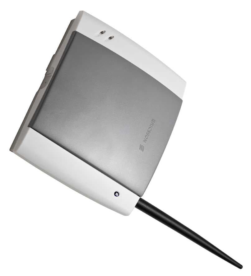
P5L-FWTG30-1
Jan 29, 2008Fixed Wireless Terminal
Equipment Class
PCB - PCS Licensed Transmitter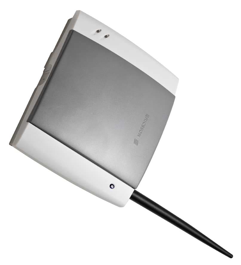
P5L-FWTG32-1
Jan 29, 2008Fixed Wireless Terminal
Equipment Class
PCB - PCS Licensed Transmitter
P5L-FWTG30
May 21, 2007Fixed Wireless Terminal
Equipment Class
PCB - PCS Licensed Transmitter
P5L0130102-BV
Jun 27, 2002Fixed Cellular Terminal
Equipment Class
PCB - PCS Licensed Transmitter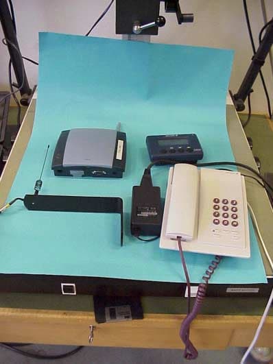
P5L0130101-BV
Jan 27, 2002Fixed Cellular Terminal
Equipment Class
PCB - PCS Licensed Transmitter