P7RM4E1Drapery Motor & Control
Electronic Solutions, Inc.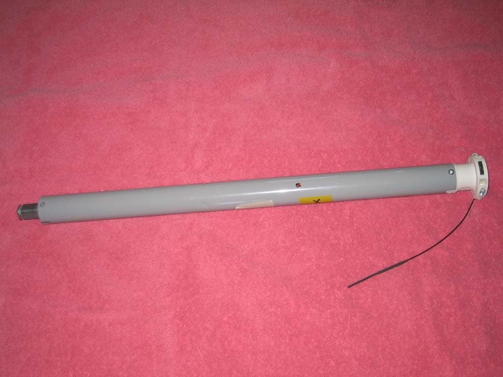
Click to zoom
Application Details
- Equipment Class
- DTS - Digital Transmission System
- Date of Grant
- Apr 07, 2011
- Application Purpose
- Original Equipment
- Date of Application
- Apr 07, 2011
- Equipment Note
- Drapery Motor & Control
- Frequency Range
- 2405.00000000 - 2480.00000000
- Company
- Electronic Solutions, Inc.
- Country
- United States
Documents & Files
Document Text
Text extracted from the exhibit documents filed with the FCC. Open a document above to read the original.
Users Manual
Electronic Solutions, Inc. Model M40Q / M50Q / M40RF / M50RF Series Operator User’s Manual & Instructions 02 February 2011 Rev. D ©2009-11 - Electronic Solutions, Inc. page 1 of 2 A. Description The Model M40Q / M50Q / M40RF / M50RF Series Operators are designed to be used with rolling window coverings and projection screens. Models M40Q / M50Q / M40RF / M50RF are designed for connection to 120V~ 60Hz supply using provided power supply cord. This system is designed for INTERIOR USE ONLY. B. Specifications See M40Q 120VAC Series Motor Specifications and Installation Instructions, M50Q 120VAC Series Motor Specifications and Installation Instructions, M40RF 120VAC Series Motor Specifications and Installation Instructions, and M50RF 120VAC Series Motor Specifications and Installation Instructions, Torque Nm Speed RPM Full Load Amperes Duty Cycle (On/Off) M40Q 228A / M40RF 228A 2 28 0.70 45 Sec / 60 Sec M40Q 430A / M40RF 430A 4 30 0.90 45 Sec / 60 Sec M40Q 915A / M40RF 915A 9 15 1.30 45 Sec / 60 Sec M50Q 330A / M50RF 330A 3 30 0.90 45 Sec / 60 Sec M50Q 634A / M50RF 634A 6 34 0.90 45 Sec / 60 Sec M50Q 1234A / M50RF 1234A 12 34 1.9 45 Sec / 60 Sec Never exceed the duty cycle or lift capacity from the above table. The stated On / Off times denote continuous operation duty cycle without motor overheating. A Motor that is cool may run for up to 4 minutes continuously before thermal overload. A motor thermal will act exactly like a stall. Thermal reset occurs after the motor has cooled sufficiently, this usually takes 10 to 15 minutes depending on ambient temperature and ventilation. C. Safety WARNING: EVALUATED FOR FIRE AND SHOCK ONLY, NOT ENTRAPMENT. SEE THESE INSTALLATION INSTRUCTIONS FOR LISTED APPLICATIONS AND LOCATION. WARNING: THIS DEVICE HAS NOT BEEN EVALUATED FOR RELIABILITY TO THE STANDARD FOR TESTS FOR SAFETY-RELATED CONTROLS EMPLOYING SOLID-STATE DEVICES, UL 991 AND THEREFORE NOT CONSIDERED SUITABLE FOR ENTRAPMENT PROTECTION. WARNING: Prior to installation inspect all parts for damage or missing components. WARNING: To Reduce the Risk Of Fire, Electric Shock, Or Injury To Persons, Installation Work And Electrical Wiring Must Be Done By Qualified Person(s) In Accordance With All Applicable Codes And Standards. WARNING: Never install this product with power connected. DISCONNECT FROM POWER SUPPLY before installing or adding accessories to this device. WARNING: Important safety instructions. It is important for the safety of persons to follow these instructions. Save these instructions. Frequently examine the installation for imbalance and signs of wear or damage to cables and springs. Do not use if repair or adjustment is necessary. Do not allow children to play with fixed controls. Keep remote controls away from children. Children should be supervised to ensure that they do not play with the appliance. The supplied UL rated grounding power cord (type SPT-2 or SJT) if lost or broken shall be only replaced with identical power cord. Replacement power cord is available from distributor or manufacturer. Power cord must be properly plugged into the electrical outlet and the M40Q / M50Q / M40RF / M50RF. Loose attachment can cause arcing and can result in failure. Any improper use or misuse can result in electrical shock causing injury to the person or persons. As with any 120V~ electrical appliance, care must be taken when handling. To reduce the risk of electric shock, this equipment has a grounding type plug, that has a third (grounding) pin. Model M40Q / M50Q / M40RF / M50RF operators are supplied with UL rated grounding power cords (type SPT-2 or SJT) that have a grounding pin which shall not be altered or removed. This plug will only fit into a grounding type outlet. If the plug does not fit into the outlet, contact a qualified electrician to install the proper outlet. Do not change the plug in any way. Use appropriate Class 2 wiring as determined by location of use or install as required by Article 725 of the NEC and local codes. Signal output is Class 2 which includes Manual Inputs and Accessory Port connection. If this device is installed in the presence of strong Radio Frequency (RF) signals (such as near RF transmitters) loss of functionality may occur. Changes or modifications not expressly approved by the party responsible for compliance could void the user’s authority to operate this equipment. If used in an area susceptible to lightning strikes or power surges, surge protectors should be used. Otherwise, unplug this operator and accessories during lightning storms. Motors are not rated for exterior use. Water can cause shorting and result in electrical shock. FOR INTERIOR USE ONLY. Before installing the operator, remove any unnecessary cords and disable any equipment not needed for powered operation. If motor malfunctions, disconnect immediately and call the installer or dealer for servicing information. USE REMOTE CONTROL ONLY WHEN THE OPERATOR IS VISIBLE AND NOT MORE THAN 15M AWAY. D. Installation: 1. This operator/motor must be installed by qualified and trained service personnel only. Electronic Solutions, Inc. Model M40Q / M50Q / M40RF / M50RF Series Operator User’s Manual & Instructions 02 February 2011 Rev. D ©2009-11 - Electronic Solutions, Inc. page 2 of 2 2. Please refer to window covering or projection screen manufacturer’s documentation for installation instructions. 3. Tubular motors are intended to be used for shades, shutters and awnings from various manufacturers and are only installed by trained service personnel. The installation shown here is only for illustration only. A typical set up (See Fig 1) will require the motor (E) to use adaptors consisting of a crown (A) and drive (B) to adapt to the corresponding tube (F). There are various types and sizes of tubes and adapters, only use the appropriate adaptors for the tube and weight in the application. The mounting of the operator to the wall (C) using a mounting bracket (D) must be securely fastened and horizon…
Text truncated - open the document above for the full version.
Cover Letter(s)
Electronic Solutions, Inc. 1355 Horizon Avenue, Lafayette, CO 80026‐9304 USA voice: +1.303.469.9322 fax: +1.303.469.5129 www.elec‐solutions.com DECLARATION OF SIMILARITY April 6, 2011 To: Bay Area Compliance Laboratories Corp. 1274 Anvilwood Ave. Sunnyvale, CA 94089 Phone: 408-732-9162, Fax: 408-732-9164 http://www.baclcorp.com Dear Sir or Madam: We Electronic Solutions, Inc. hereby declare that product: Motor Control, model(s): M40RF is/are electrically identical with the same electromagnetic emissions and electromagnetic compatibility characteristics as model: M50RF tested by Criterion Technology, the results of which are featured in the EMC test report: 100232-1548. A description of the differences between the tested model and those that are declared similar are as follows: The models M40RF and M50RF use the same identical electronic control circuit board and components. The only difference is the size of the enclosure tube. The M40RF uses a 40mm diameter tube and the M50RF uses a 50 mm tube. Please contact me should there be need for any additional clarification or information. Best Regards, Douglas Barnes Electronic Solutions, Inc. 1355 Horizon Ave. Lafayette, CO 80026, USA
ID Label/Location Info
2Nm28rpm 120V~ 60Hz0.70FLA 45 sec ONV 1.0 60 sec OFFIP 30 40°C +/– 56 turns FCC ID P7RM4E1 IC: 7206A-M4E1 Window Shade Operator Made in Italy 4Nm30rpm 120V~ 60Hz0.90FLA 45 sec ONV 1.0 60 sec OFFIP 30 40°C +/– 60 turns FCC ID P7RM4E1 IC: 7206A-M4E1 Window Shade Operator Made in Italy 9Nm15rpm 120V~ 60Hz1.3FLA 45 sec ONV 1.0 60 sec OFFIP 30 40°C +/– 30 turns FCC ID P7RM4E1 IC: 7206A-M4E1 Window Shade Operator Made in Italy M40RF 915A 3SMW E317985 8888 *barcode* 9 999999 999994 Class 2 Inputs M40RF 228A Class 2 Inputs M40RF 430A 3SMW E317985 8888 *barcode* 9 999999 999994 3SMW E317985 8888 *barcode* 9 999999 999994 Class 2 Inputs 3Nm30rpm 120V~ 60Hz.90FLA 45 sec ONV 1.0 60 sec OFFIP 30 40°C +/– 60 turns FCC ID P7RM4E1 IC: 7206A-M4E1 Window Shade Operator Made in Italy 6Nm34rpm 120V~ 60Hz.90FLA 45 sec ONV 1.0 60 sec OFFIP 30 40°C +/– 68 turns FCC ID P7RM4E1 IC: 7206A-M4E1 Window Shade Operator Made in Italy 12Nm34rpm 120V~ 60Hz1.08FLA 45 sec ONV 1.0 60 sec OFFIP 30 40°C +/– 68 turns FCC ID P7RM4E1 IC: 7206A-M4E1 Window Shade Operator Made in Italy M50RF 1234A 3SMW E317985 8888 *barcode* 9 999999 999994 M50RF 634A 3SMW E317985 8888 *barcode* 9 999999 999994 Class 2 Inputs M50RF 330A 3SMW E317985 8888 *barcode* 9 999999 999994 Class 2 Inputs Class 2 Inputs
Internal Photos
Internal l Photos
Test Report
• P.O. Box 489 • 1350 Tolland Road • Rollinsville, CO 80474 • Phone: (303) 258-0100 • FAX: (303) 258-0775 • • www.criteriontech.com • CONFIDENTIAL AND PROPRIETARY EMC QUALIFICATION TEST REPORT ELECTRONIC SOLUTIONS, INC. DRAPERY MOTOR AND CONTROLLER, M40RF, M40Q, M50RF, M50Q FCC ID# P7RM4E1 TESTED TO CONFORM WITH: EMISSIONS STANDARDS FOR INDUSTRIAL, SCIENTIFIC AND MEDICAL (ISM) Test Report Number: 100323-1548FCC Date of Test Completion: February 25, 2011 Manufacturer’s Address: 1355 Horizon Ave Lafayette, CO 80026 Phone: (303) 469-9322 Approved by: Laboratory Director DOCUMENT REVISION HISTORY REVISION # REPORT NUMBER DESCRIPTION OF REVISION DATE OF REVISION 0 100323-1548FCC ORIGINAL REPORT 2011-02-17 1 100323-1548FCC REVISED FCC STANDARD REFERENCE 2011-02-22 2 100323-1548FCC ADDITIONAL TEST DATA ADDED 2011-04-05 Sheet 2 of 53 EMC QUALIFICATION TEST REPORT CRITERION TECHNOLOGY 100323-1548FCC FOR ELECTRONIC SOLUTIONS, INC. CONFIDENTIAL AND PROPRIETARY DISCLAIMERS This report is the confidential property of the client. For the protection of our clients and ourselves, extracts from this test report cannot be produced without prior written approval from Criterion Technology. Reproduction of the complete report can be performed at the client’s discretion. The client is aware that Criterion Technology has performed testing in accordance with the applicable standard(s). Test data is accurate within ANSI parameters for Emissions testing, unless a specific level of accuracy has been defined in writing prior to testing, by Criterion Technology and the client. Criterion Technology reports apply only to the specific Equipment Under Test (EUT) sample(s) tested under the test conditions described in this report. If the manufacturer intends to use this report as a document demonstrating compliance of this model, additional models of this product must have electrical and mechanical characteristics identical to the device tested for this report. Criterion Technology shall have no liability for any deductions, inferences, or generalizations drawn by the client or others from Criterion Technology issued reports. Total liability is limited to the amount invoiced for the testing of this EUT and the contents of this report are not warranted. Compliance with the appropriate governmental standards is the responsibility of the manufacturer. Any questions regarding this report should be directed to: Laboratory Director Criterion Technology Corp. P.O. Box 489 1350 Tolland Road Rollinsville, Colorado 80474 Phone: (303) 258-0100 Fax: (303) 258-0775 mailto:[email protected] NVLAP Note: Criterion Technology is accredited by the National Voluntary Laboratory Accreditation Program (NVLAP) for the specific scope of accreditation under Lab Code 100396-0. This report may contain data which is not covered by the NVLAP accreditation. This report must not be used by the client to claim product endorsement by NIST or any agency of the Federal Government. Criterion Technology has been accredited by the following groups: NVLAP (#100396-0) FCC (#90688) BSMI (#SL2-IN-007R) VCCI (#1255) 3&10 meter site (#R-2826), Immunity Shield room(#C-3118), Open Area Site(#C-3119) Nemko (#ELA-214) NMi (EU Competent Body Accreditation) Industry Canada (#IC 3301A-1). The National Institute for Standards and Technology (NIST) has designated Criterion Technology a Conformity Assessment Body (CAB) for Taiwan (BSMI # SL2-IN-E-007R) and Korea (US0026). All Criterion Technology instrumentation and accessories used to test products for compliance to the indicated standards are calibrated regularly in accordance with ISO 9002, ISO 17025, ANSI/NCSL Z540-I-1994 and are traceable to national standards. CRITERION TECHNOLOGY EMC QUALIFICATION TEST REPORT Sheet 3 of 53 100323-1548FCC FOR ELECTRONIC SOLUTIONS, INC. CONFIDENTIAL AND PROPRIETARY TABLE OF CONTENTS 1.0 EXECUTIVE SUMMARY........................................................................................................................................................................4 1.1 PURPOSE....................................................................................................................................................................................................4 1.2 CONFORMITY..........................................................................................................................................................................................4 1.3 EQUIPMENT UNDER TEST (EUT).....................................................................................................................................................4 2.0 EMISSIONS TEST STANDARDS..........................................................................................................................................................5 2.1 UNINTENTIONAL RADIATED EMISSIONS – 30 MHZ TO 1000 MHZ – M40RF& M40Q.................................................5 2.2 UNINTENTIONAL RADIATED EMISSIONS – 30 MHZ TO 1000 MHZ – M50RF & M50Q...............................................6 2.3 UNINTENTIONAL RADIATED EMISSIONS – ABOVE 1 GHZ – M40RF & M40Q..............................................................7 2.4 UNINTENTIONAL RADIATED EMISSIONS – ABOVE 1 GHZ – M50RF & M50Q..............................................................8 2.5 INTENTIONAL RADIATOR – RADIATED EMISSIONS – M40RF............................................................................................9 2.6 INTENTIONAL RADIATOR – RADIATED EMISSIONS – M50RF..........................................................................................10 2.7 FREQUENCY LIMITS – M40RF.........................................................................................................................................................11 2.8 FREQUENCY LIMITS – M50RF......................................................................................................................................................…
Text truncated - open the document above for the full version.
Test Setup Photos
CRITERION TECHNOL OGY EMC QUALIFICATION TEST REPORT Sheet 17 of 53 100323-1548FCC FOR ELECTRONICSOLUTIONS,INC. CONFIDENTIAL AND PROPRIETARY 3.0 APPENDIX A: EUT PHOTOGRAPHS 3.1UNINTENTIONAL RADIATED EMISSIONS Sheet 18 of 53 EMC QUALIFICATION TEST REPORT CRITERION TECHNOLOGY 100323-1548FCC FOR ELECTRONICSOLUTIONS,INC. CONFIDENTIAL AND PROPRIETARY 3.2CONDUCTED EMISSIONS
Contact Information
Applicant
Brian Hodd(engineering manager)
Test Firm
Compliance Worldwide, Inc.Deb Bourbeau
Technical Specifications
| # | Rule Parts | Frequency Range | Power Output |
|---|---|---|---|
| 1 | 15C | 2.40 GHz - 2.48 GHz | 10.00 mW |
Other Applications from Electronic Solutions, Inc.
P7RRFRQTRANS
Feb 13, 2013Remote Control
Equipment Class
DTS - Digital Transmission System
P7RRFSWTINTRFC
Sep 17, 2012Remote Control
Equipment Class
DTS - Digital Transmission System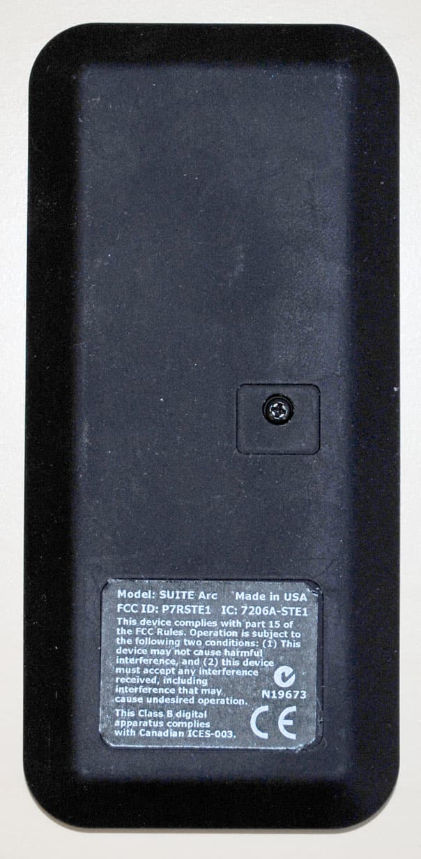
P7RSTE1
Dec 29, 2011Remote Control
Equipment Class
DTS - Digital Transmission System
P7RZWRQREC
Mar 26, 2010Z-Wave dongle control
Equipment Class
DXX - Part 15 Low Power Communication Device Transmitter
P7R433DT1
Apr 16, 2006Transmitter
Equipment Class
DSC - Part 15 Security/Remote Control Transmitter