P7RSTE1Remote Control
Electronic Solutions, Inc.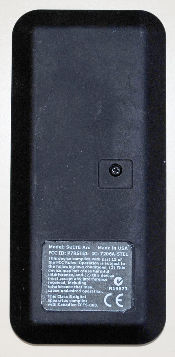
Click to zoom
Application Details
- Equipment Class
- DTS - Digital Transmission System
- Date of Grant
- Dec 29, 2011
- Application Purpose
- Original Equipment
- Date of Application
- Dec 29, 2011
- Equipment Note
- Remote Control
- Frequency Range
- 2405.00000000 - 2480.00000000
- Company
- Electronic Solutions, Inc.
- Country
- United States
Documents & Files
Document Text
Text extracted from the exhibit documents filed with the FCC. Open a document above to read the original.
Users Manual
Single Motor (Hub) and Remote IMPORTANT: Prior to motor network setup, install batteries into the SUITE Remote and wait for the LEDs to go out (“asleep”). Create the Hub Motor — Power up one factory default motor which automatically establishes it as the Hub. 1 (a) Connect AC power to the motor. On motor, Yellow LED is solid and Red LED is flashing (indicates end limits are not set). 2 (b) Wait until motor jogs twice. Could take up to 3 minutes. (c) Motor is now the Hub motor. Yellow LED begins flashing for 60 seconds (indicates Network Invite Mode). 3 Important Installation Information When shipped, the remote is in Setup Mode to facilitate creation of a motor network. When network creation is finished and ready for the end user, you must exit Setup Mode on the remote. For best RF performance, the antenna on the motor should maintain as much separation from a conductive surface as possible. Glossary Hub Motor - Special designation for the first motor powered up. All commands to additional motors are routed through the Hub motor. Jog Once - Motor moves a short distance in one direction. Jog Twice - Motor moves a short distance in two directions. Remote - The RF transceiver used to set up and operate motors. Asleep - The default state of a remote is ―asleep‖ — no LEDs are lit. ―Wake Up‖ remote: press and release the UP or DOWN button. Group - A collection of up to four motors controlled by Group 1, 2, 3, or 4 on an Arc transceiver or Group 1 on a Step transceiver. LED - Light-emitting diode. Both the remote and the motor head have LEDs in three colors. Blink - A single on/off of an LED. Flash - LED turns on and off continuously. M40/50RF Motor The M40/50RF motor is equipped with radio frequency technology and has three buttons with internal LEDs that provide visual feedback during setup and operation. Green LED – Button operates the motor in one direction. Yellow LED – Center Button is used for motor administration. Red LED – Button operates the motor in the other direction. SUITE Remote The SUITE Remote is equipped with radio frequency technology for wireless control of all ESI RF-enabled motors. The SUITE Step remote controls one group of up to four motors. The SUITE Arc remote controls four groups of up to four motors each, for a total of sixteen motors. Wake Up the Remote The remote must be ―awake‖ to send or receive commands. To wake up a remote that is ―asleep‖ (no LEDs are lit): Press and release the UP or DOWN button. NOTE: When no buttons are pressed, the remote goes to sleep after 10 seconds while in User Mode, or after 60 seconds while in Setup Mode. Blink or Flash = Solid = M40/50RF System Quick Setup Guide © 2011 Electronic Solutions, Inc. 1355 Horizon Avenue, Lafayette, CO 80026 U.S.A. Tel: (303) 469-9322 www.elec-solutions.com M40/50RF System September 2011, rev 2 - DRAFT © 2011 Electronic Solutions, Inc. Page 2 of 7 Join the Remote to the Hub Motor (a) “Wake up” the remote if no LEDs are lit (asleep). Press and release the UP or DOWN button. Green “preset” LED is solid (Network Search Mode). 4 (b) Put Hub motor into Network Invite Mode. NOTE: if the Yellow LED on the motor is flashing, Skip to Step 2 (d). Press and release the Center button once. (c) On the Hub motor. Yellow LED flashes for 60 seconds to indicate new devices may join. (d) Remote automatically joins the Hub and forms a network. Green “preset” LED blinks once, and Hub motor jogs once, then jogs twice. (e) Remote is in Setup Mode. Red LED under “preset” is solid, and Yellow LED under Group 1 is solid. The UP and DOWN buttons are flashing (indicates no end limits are set). Toggle Motor Direction — Check the motor travel direction using the remote. (a) Verify travel direction. Press the UP or DOWN button. If the shade moves as expected, skip to Step 4. (b) Toggle the motor direction. Simultaneously press and hold the UP and DOWN buttons for 5 seconds until the motor jogs once. Motor direction is now reversed. (c) Verify the direction change. Press the UP or DOWN button. Set Limits (a) Adjust shade to Upper limit position. Press and hold the UP button. (b) Set the Upper end limit. Simultaneously press and hold STOP and UP until motor jogs twice (approximately 2 seconds). (c) Upper end limit is set. Yellow LED on UP button turns off. M40/50RF System September 2011, rev 2 - DRAFT © 2011 Electronic Solutions, Inc. Page 3 of 7 Set Limits (continued) (d) Adjust shade to Lower limit position. Press and hold the DOWN button. (e) Set the Lower end limit. Simultaneously press and hold STOP and DOWN until motor jogs twice (approximately 2 seconds). (f) Lower end limit is set. Yellow LED on DOWN button turns off. Set “preset” (OPTIONAL) (a) Adjust shade to desired “preset” position. NOTE: Both end limits must be set prior to setting a ―preset‖ position. Press and hold the UP (or DOWN) button. (b) Set the “preset.” Press and hold “preset” until motor jogs twice (approximately 5 seconds) then release. Adjust Limits / Clear Limits (a) Adjust the Upper or Lower end limits. NOTE: To set an end limit outside of a current end limit, you must clear that end limit first. Clear Upper Limit: Simultaneously press and hold STOP and UP until motor jogs twice, then jogs once (approximately 5 seconds), then release. The UP button flashes to show its limit is cleared. Clear Lower Limit: repeat the above two instructions using the DOWN button (instead of UP). (b) Set the new Upper or Lower end limit. UPPER: see Step 4 (a), (b), (c). LOWER: see Step 4 (d), (e), (f). ------------------------------------------------ (c) Adjust the “preset” limit. NOTE: A ―preset‖ cannot be cleared using the remote, only readjusted. Follow the instructions in Step 5. Finish the Installation NOTE: If this is a single motor installation, complete Step 7 now, otherwise continue with Step 8 for a multiple motor installation. (a) On the remote, you must exit Setup Mode and put the remote into User Mod…
Text truncated - open the document above for the full version.
Cover Letter(s)
1076 Deer Clover Way • Castle Rock, Colorado 80108 USA • Phone 303 663 3396 • Fax 303 663 5545 e-mail: [email protected] The information in this document is private and company confidential "your compliance solution" Request for Confidentiality Date: December 29, 2011 Subject: Confidentiality Request for: ______FCC ID: P7RSTE1, IC 7206A-STE1______ Pursuant to FCC 47 CRF 0.457(d) and 0.459 and IC RSP-100, Section 10, the applicant requests that a part of the subject FCC application be held confidential. Type of Confidentiality Requested Exhibit Short Term x Permanent Block Diagrams Short Term External Photos Short Term Permanent* 1 Internal Photos Short Term x Permanent Operation Description/Theory of Operation Short Term x Permanent Parts List & Placement/BOM Short Term Permanent Tune-Up Procedure Short Term x Permanent Schematics Short Term Test Setup Photos Short Term Permanent* User’s Manual *Note: ______(Insert Explanation as Necessary)______ ______Electronic Solutions , Inc._____ has spent substantial effort in developing this product and it is one of the first of its kind in industry. Having the subject information easily available to "competition" would negate the advantage they have achieved by developing this product. Not protecting the details of the design will result in financial hardship. Permanent Confidentiality: The applicant requests the exhibits listed above as permanently confidential be permanently withheld from public review due to materials that contain trade secrets and proprietary information not customarily released to the public. Short-Term Confidentiality: The applicant requests the exhibits selected above as short term confidential be withheld from public view for a period of ___0__ days from the date of the Grant of Equipment Authorization and prior to marketing. This is to avoid premature release of sensitive information prior to marketing or release of the product to the public. Applicant is also aware that they are responsible to notify ACB in the event information regarding the product or the product is made available to the public. ACB will then release the documents listed above for public disclosure pursuant to FCC Public Notice DA 04-1705. 1 - The asterisked items (*) require further justification before permanent confidentiality will be allowed. These also currently require review by the FCC under their Permit-But-Ask policy before the grant is issued and can delay completion of an application. Further justification should be added to the note above. One such example for a potted device would be: “The EUT is FULLY potted using a non-removable epoxy based material. Removal of potting material causes irreparable damage to internal circuitry. See photographs exhibits that outline the device before and after potting.” 1076 Deer Clover Way • Castle Rock, Colorado 80108 USA • Phone 303 663 3396 • Fax 303 663 5545 e-mail: [email protected] The information in this document is private and company confidential NOTE for Industry Canada Applications: The applicant understands that until such time that IC distinguishes between Short Term and Permanent Confidentiality, either type of marked exhibit above will simply be marked Confidential when submitted to IC. Sincerely, By: J Douglas Barnes / Agent (Signature/Title 2 ) (Print name) 2 - Must be signed by applicant contact given for applicant on the FCC site, or by the authorized agent if an appropriate authorized agent letter has been provided. Letters should be placed on appropriate letterhead.
Cover Letter(s)
This application is for a family of remote controls. Differences between SUITE Arc and Step remote control are as follows: STEP: A single channel remote with three operating buttons and a ""SUITE"" button. These will Open/Stop/Close a single motor. The "SUITE" button will send an intermediate position movement. ARC: A 4 channel remote with three operating buttons and a "SUITE" Button. These will Open/Stop/Close a single motor. The "SUITE" button will administer an intermediate position movement. To select which motor or group of motors a person would wish to operate, you will press a number across the top of the remote. This will activate an LED. When activated, the remote will output that channel Both remotes use the same RF circuitry, the only difference is the number of buttons and the software. The ARC model is what was tested.
ID Label/Location Info
Model: SUITE Arc FCC ID: P7RSTE1 IC: 7206A-STE1 This device complies with part 15 of the FCC Rules. Operation is subject to the following two conditions: (1) This device may not cause harmful interference, and (2) this device must accept any interference received, including interference that may cause undesired operation. This Class B digital apparatus complies with Canadian ICES-003. N19673 Made in USA
ID Label/Location Info
Model: SUITE Step FCC ID: P7RSTE1 IC: 7206A-STE1 This device complies with part 15 of the FCC Rules. Operation is subject to the following two conditions: (1) This device may not cause harmful interference, and (2) this device must accept any interference received, including interference that may cause undesired operation. This Class B digital apparatus complies with Canadian ICES-003. N19673 Made in USA
Test Report
P.O. Box 489 1350 Tolland Road Rollinsville, CO 80474 Phone: (303) 258-0100 FAX: (303) 258-0775 www.criteriontech.com CONFIDENTIAL AND PROPRIETARY EMC QUALIFICATION TEST REPORT ELECTRONIC SOLUTIONS, INC. A HUNTER DOUGLAS COMPANY REMOTE CONTROL, SUITE Arc & SUITE Step FCC ID# P7RSTE1 TESTED TO CONFORM WITH: EMISSIONS STANDARDS FOR INDUSTRIAL, SCIENTIFIC AND MEDICAL (ISM) Test Report Number: 110211-1669FCC Date of Test Completion: June 28, 2011 Manufacturer’s Address: 1355 Horizon Ave Lafayette, CO 80026 Phone: (303) 469-9322 DOCUMENT REVISION HISTORY REVISION # REPORT NUMBER DESCRIPTION OF REVISION DATE OF REVISION 0 110211-1669FCC ORIGINAL REPORT 2011-08-22 1 110211-1669FCC ADDED ADDITIONAL TESTING INFORMATION AND DATA 2011-11-23 2 110211-1669FCC ADDED ADDITIONAL TESTING INFORMATION AND DATA 2011-12-21 Approved by: Laboratory Director Sheet 2 of 30 EMC QUALIFICATION TEST REPORT CRITERION TECHNOLOGY 110211-1669FCC FOR ELECTRONIC SOLUTIONS, INC. CONFIDENTIAL AND PROPRIETARY DISCLAIMERS This report is the confidential property of the client. For the protection of our clients and ourselves, extracts from this test report cannot be produced without prior written approval from Criterion Technology. Reproduction of the complete report can be performed at the client’s discretion. The client is aware that Criterion Technology has performed testing in accordance with the applicable standard(s). Test data is accurate within ANSI parameters for Emissions testing, unless a specific level of accuracy has been defined in writing prior to testing, by Criterion Technology and the client. Criterion Technology reports apply only to the specific Equipment Under Test (EUT) sample(s) tested under the test conditions described in this report. If the manufacturer intends to use this report as a document demonstrating compliance of this model, additional models of this product must have electrical and mechanical characteristics identical to the device tested for this report. Criterion Technology shall have no liability for any deductions, inferences, or generalizations drawn by the client or others from Criterion Technology issued reports. Total liability is limited to the amount invoiced for the testing of this EUT and the contents of this report are not warranted. Compliance with the appropriate governmental standards is the responsibility of the manufacturer. Any questions regarding this report should be directed to: Laboratory Director Criterion Technology Corp. P.O. Box 489 1350 Tolland Road Rollinsville, Colorado 80474 Phone: (303) 258-0100 Fax: (303) 258-0775 mailto:[email protected] NVLAP Note : Criterion Technology is accredited by the National Voluntary Laboratory Accreditation Program (NVLAP) for the specific scope of accreditation under Lab Code 100396-0. This report may contain data which is not covered by the NVLAP accreditation. This report must not be used by the client to claim product endorsement by NIST or any agency of the Federal Government. Criterion Technology has been accredited by the following groups: NVLAP (#100396-0) FCC (#90688) BSMI (#SL2-IN-007R) VCCI (#1255) 3&10 meter site (#R-2826), Immunity Shield room(#C-3118), Open Area Site(#C-3119) Nemko (#ELA-214) NMi (EU Competent Body Accreditation) Industry Canada (#IC 3301A-1). The National Institute for Standards and Technology (NIST) has designated Criterion Technology a Conformity Assessment Body (CAB) for Taiwan (BSMI # SL2-IN-E-007R) and Korea (US0026). All Criterion Technology instrumentation and accessories used to test products for compliance to the indicated standards are calibrated regularly in accordance with ISO 9002, ISO 17025, ANSI/NCSL Z540-I-1994 and are traceable to national standards. CRITERION TECHNOLOGY EMC QUALIFICATION TEST REPORT Sheet 3 of 30 110211-1669FCC FOR ELECTRONIC SOLUTIONS, INC. CONFIDENTIAL AND PROPRIETARY TABLE OF CONTENTS 1.0 EXECUTIVE SUMMARY...................................................................................................................................................... 4 1.1 PURPOSE .............................................................................................................................................................................. 4 1.2 CONFORMITY ..................................................................................................................................................................... 4 1.3 EQUIPMENT UNDER TEST (EUT) .................................................................................................................................... 4 2.0 EMISSIONS TEST STANDARDS ......................................................................................................................................... 5 2.1 UNINTENTIONAL RADIATED EMISSIONS – 30 MHZ TO 1000 MHZ ......................................................................... 5 2.2 RECEIVER SPURIOUS & UNINTENTIONAL RADIATED EMISSIONS ....................................................................... 6 2.3 INTENTIONAL RADIATOR – RADIATED EMISSIONS ................................................................................................. 7 2.4 FREQUENCY LIMITS.......................................................................................................................................................... 8 2.5 POWER SPECTRAL DENSITY........................................................................................................................................... 9 3.0 APPENDIX A: EUT PHOTOGRAPHS .............................................................................................................................. 10 3.1 UNINTENTIONAL RADIATED EMISSIONS .................................................................................................................. 10 4.0 APPENDIX B: DATA SHEETS .....................................................................................................................…
Text truncated - open the document above for the full version.
Test Setup Photos
TEST SETUP PHOTOS Electronic Solutions, Inc A Hunter Douglas Company Test Report Number: 110211-1669 EUT NAME(S): Remote Control EUT NAME(S): SUITE Arc & SUITE Step Unintentional Radiated emissions
Contact Information
Applicant
Brian Hodd(engineering manager)
Technical Contact
Compliance & More, Inc.Douglas Barnes
[email protected]303-663-3396
1076 Deer Clover Way · Castle Rock, Colorado · United States
Test Firm
Criterion Technology Corp.Lou Schornack
Technical Specifications
| # | Rule Parts | Frequency Range | Power Output |
|---|---|---|---|
| 1 | 15C | 2.40 GHz - 2.48 GHz | 3.48 mW |
Other Applications from Electronic Solutions, Inc.
P7RRFRQTRANS
Feb 13, 2013Remote Control
Equipment Class
DTS - Digital Transmission System
P7RRFSWTINTRFC
Sep 17, 2012Remote Control
Equipment Class
DTS - Digital Transmission System
P7RM4E1
Apr 07, 2011Drapery Motor & Control
Equipment Class
DTS - Digital Transmission System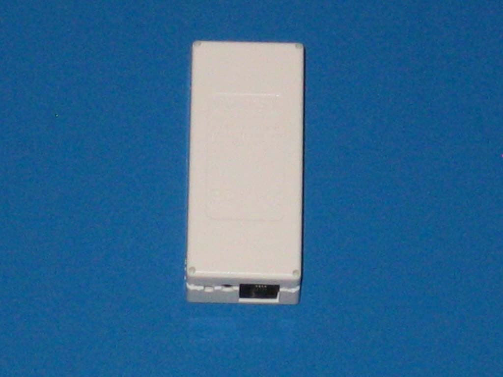
P7RZWRQREC
Mar 26, 2010Z-Wave dongle control
Equipment Class
DXX - Part 15 Low Power Communication Device Transmitter
P7R433DT1
Apr 16, 2006Transmitter
Equipment Class
DSC - Part 15 Security/Remote Control Transmitter