P7RT24AP433Remote Control Device
Electronic Solutions, Inc.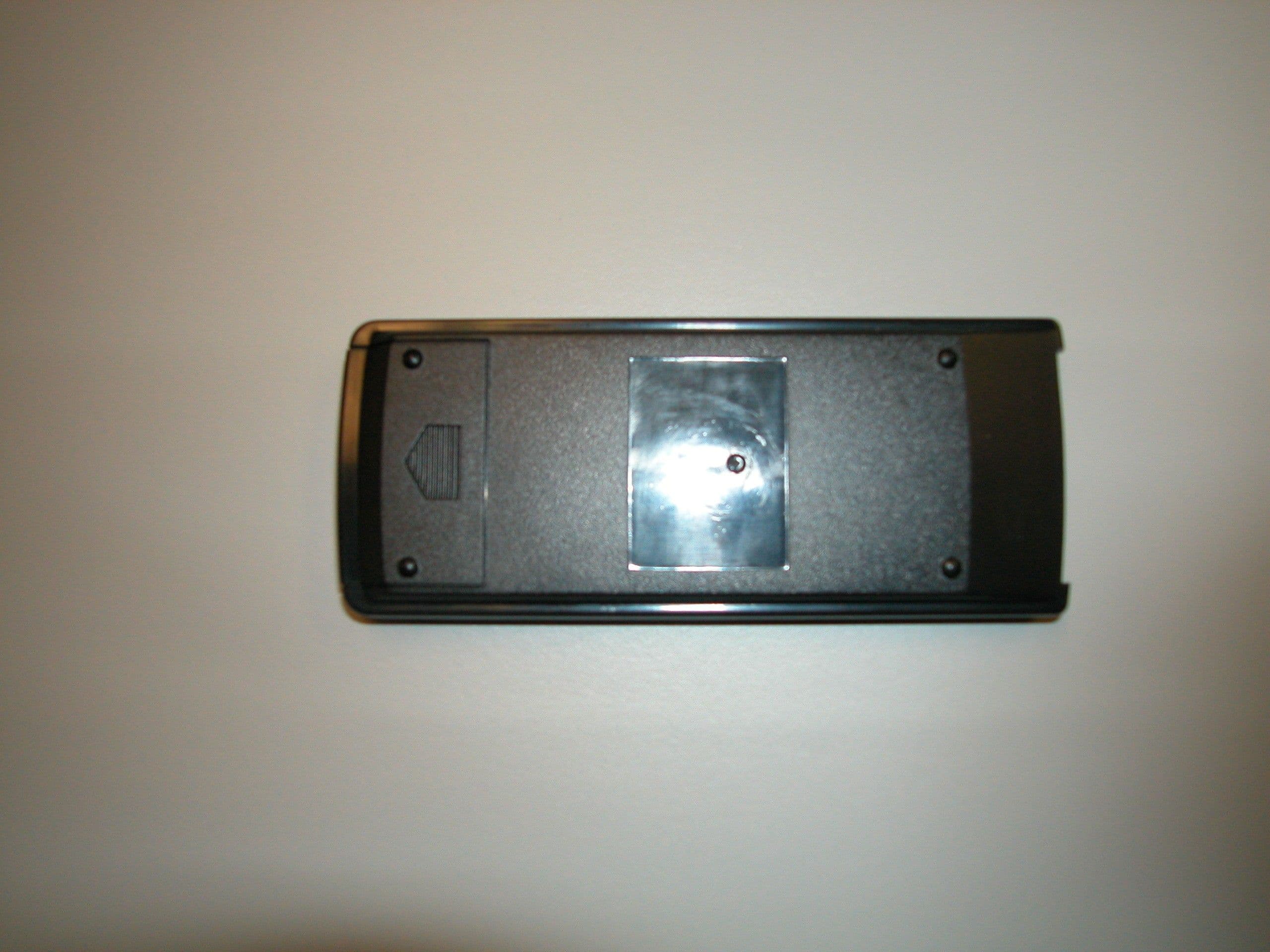
Click to zoom
Application Details
- Equipment Class
- DSC - Part 15 Security/Remote Control Transmitter
- Date of Grant
- Mar 30, 2004
- Application Purpose
- Original Equipment
- Date of Application
- Mar 30, 2004
- Equipment Note
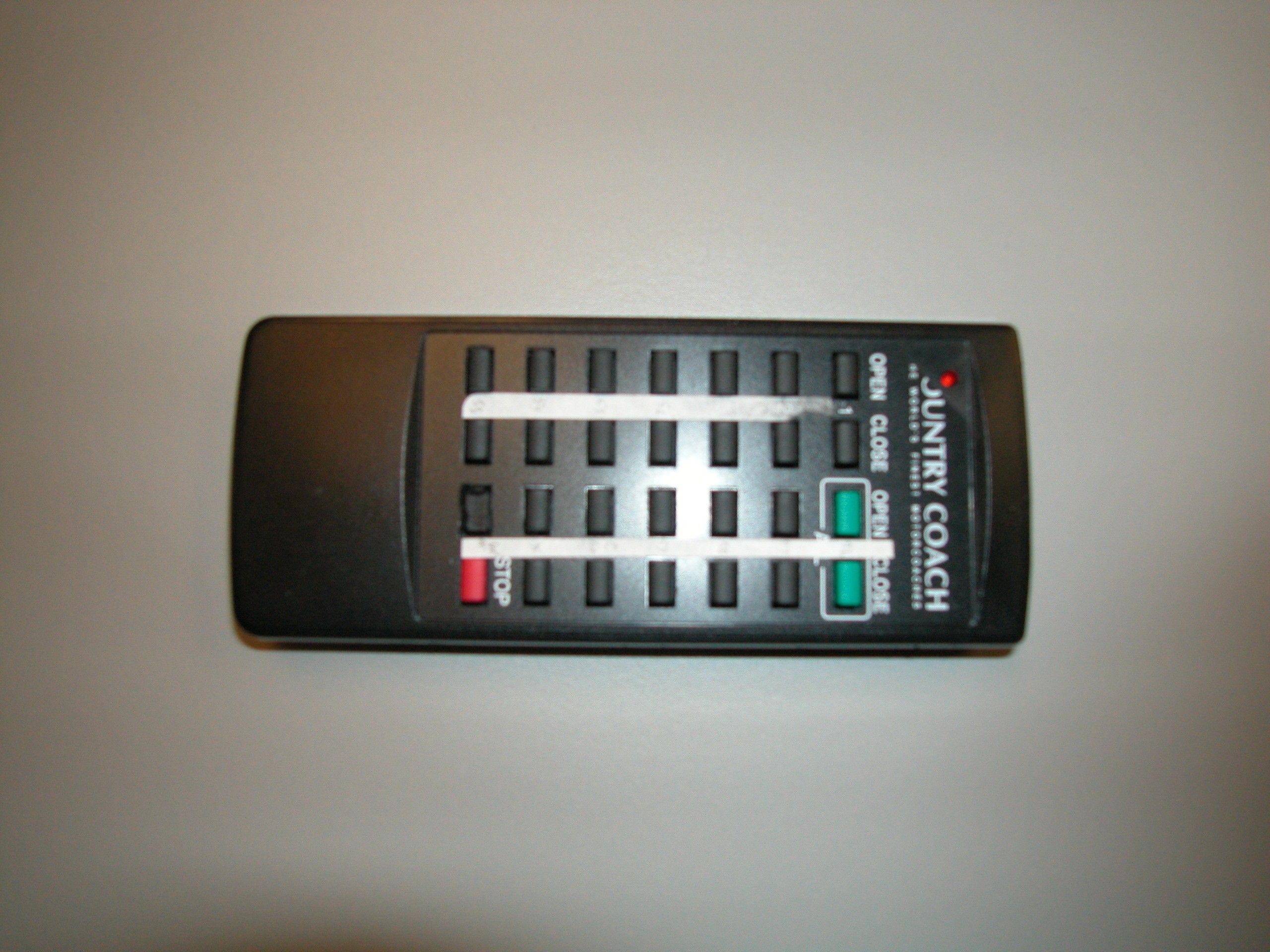
- Remote Control Device
- Frequency Range
- 433.92000000 - 433.92000000
- Company
- Electronic Solutions, Inc.
- Country
- United States
Documents & Files
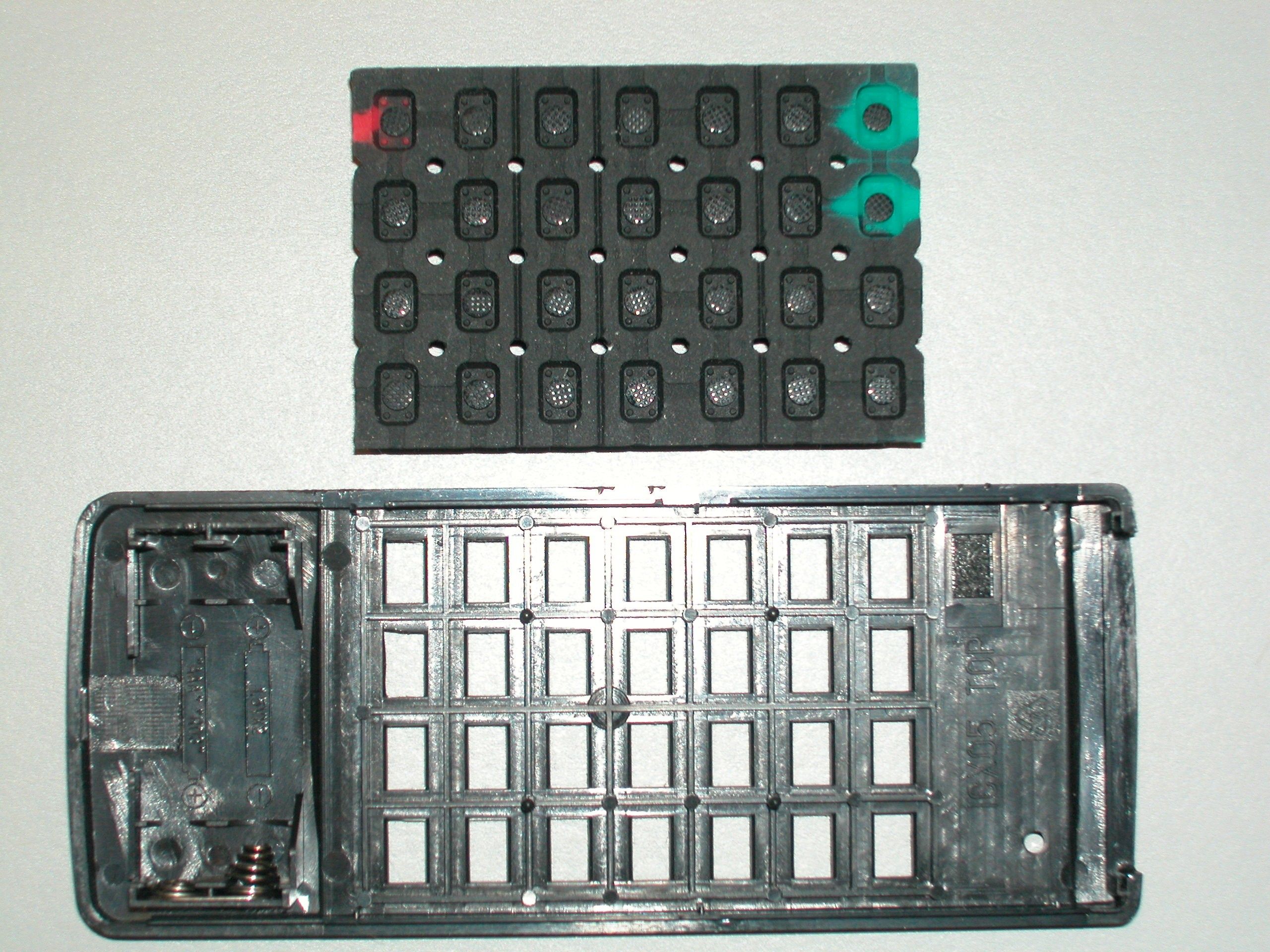
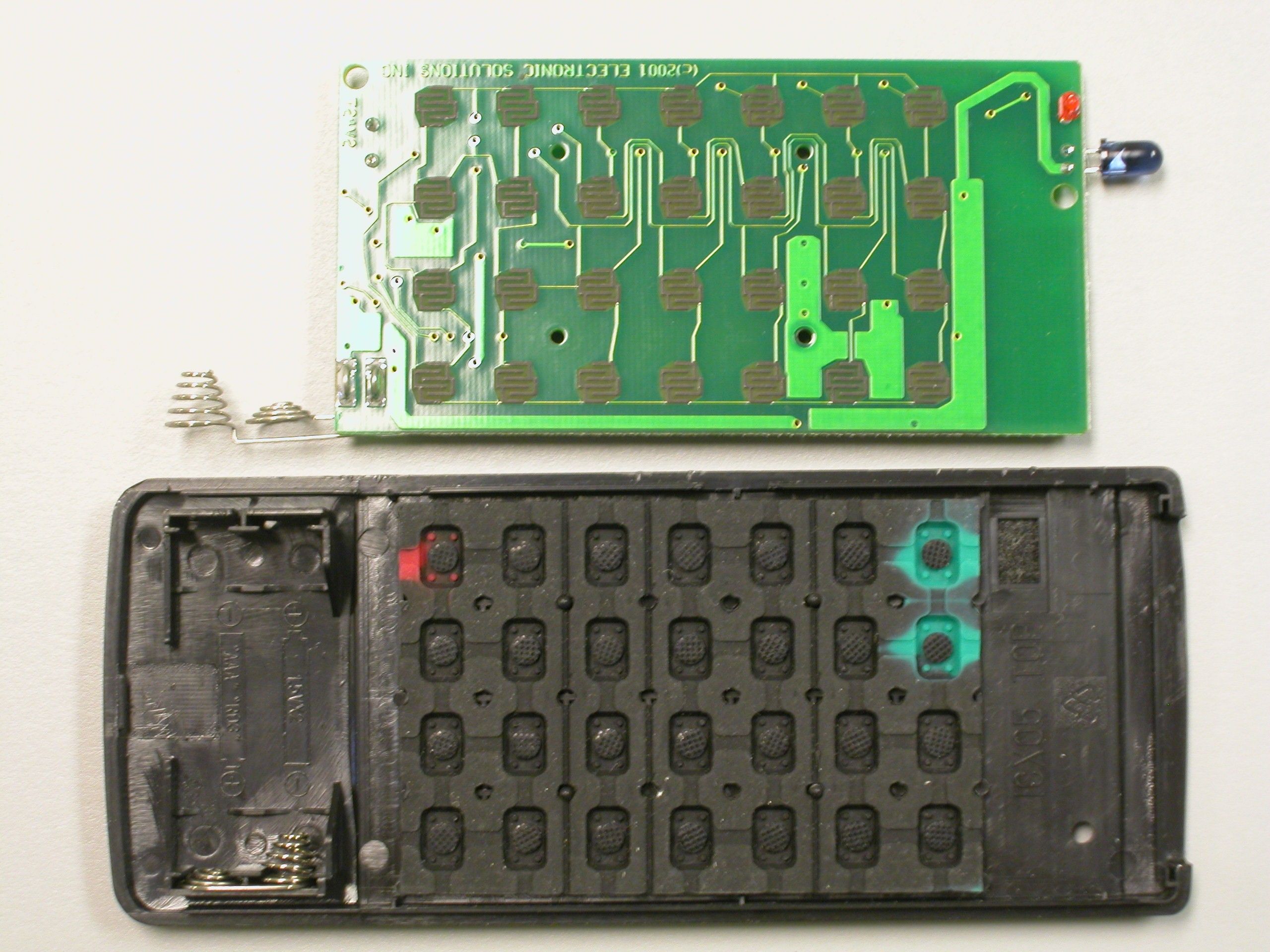
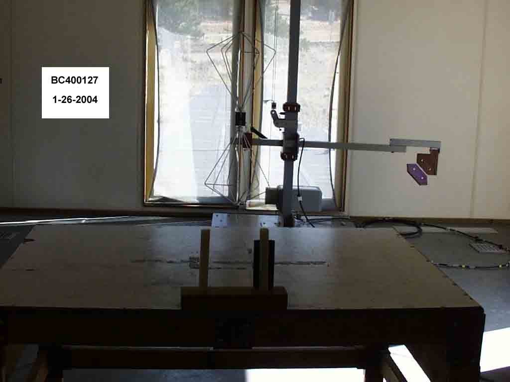
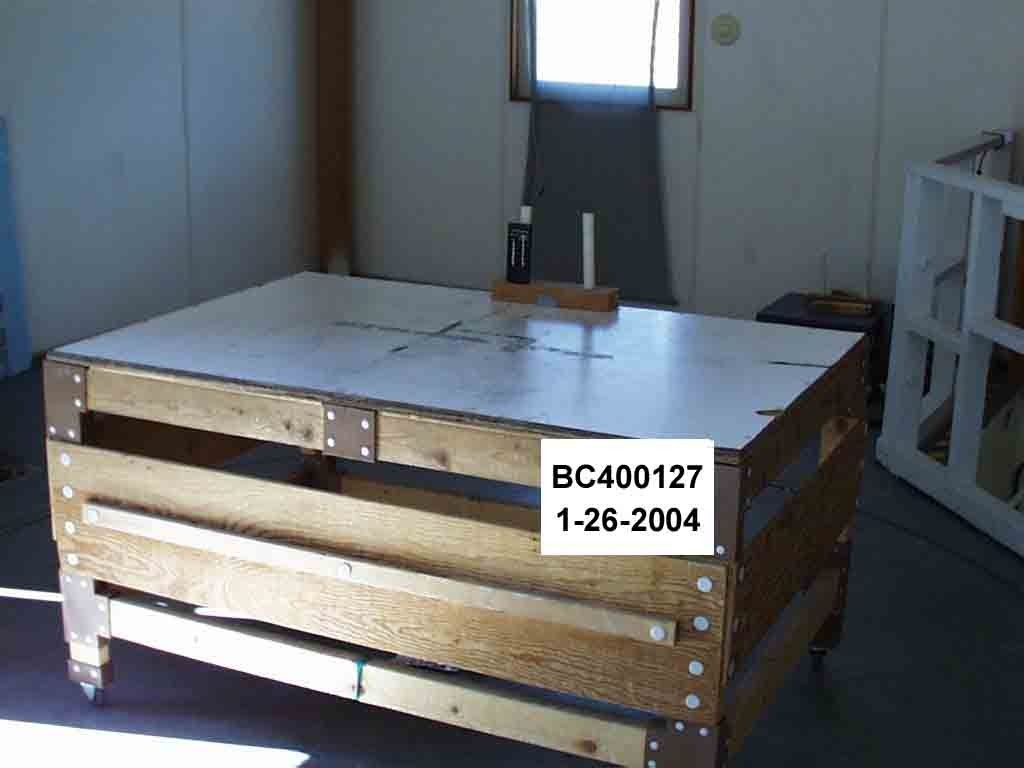
Document Text
Text extracted from the exhibit documents filed with the FCC. Open a document above to read the original.
Users Manual
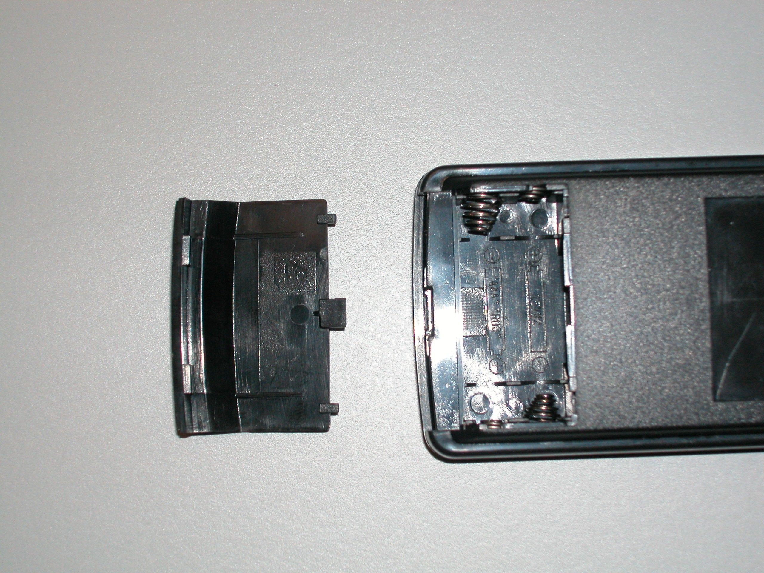
12/1/03 Electronic Solutions, Inc. 11811 Upham St. Unit #2, Broomfield, CO 80020-2710 voice: 303-469-9322 fax: 303-469-5129 www.elec-solutions.com Electronic Solutions, Inc. T24A-Pdual433 with RR24 connected to RP24/RP60 Operation & Installation Manual December 15, 2003 Specifications: T24A-Pdual433 Transmitter Power Supply Voltage 3V (2 AAA batteries) Frequency 433.92 MHz RR24 Receiver Power Supply Voltage 5V (provided via RP24 or RP60) 12/1/03 Electronic Solutions, Inc. 11811 Upham St. Unit #2, Broomfield, CO 80020-2710 voice: 303-469-9322 fax: 303-469-5129 www.elec-solutions.com RR24 Installation Guide Connect the RR24 Radio Receiver to the RP24/RP60 as shown The RR24 unit must connect to an Eye Jack on a RP24/RP60 or splitter. If the eye connects to a splitter, then the Main jack next to it must connect to the Eye Jack on an RP24/RP60. For best reception, the RR24 should be mounted with the antenna pointing up, and it should not be placed on or near a metal surface. The RR24 unit can learn up to 5 different transmitters to work with. It ships from the factory with NO transmitters learned, you must train it in the field to work with your specific transmitters. Press and release the “Learn Transmitter” button on the RR24, the red LED will come on if 5 transmitters have not already been learned, the unit is now ready to learn another radio transmitter: Press stop on the radio transmitter, (buttons other than stop are ignored) The LED on the RR24 will go out, this transmitter is added to the list of known transmitters, the RR24 is now operating normally again. Note that if this transmitter is already known, this button will be ignored and the LED will remain lit. If no stop command is received within 10 seconds, the red LED will flash off, then on, and then go out. NO new transmitters were learned! (Note that if no transmitters are known at all, then the LED will turn back on immediately) If the red LED is on and the learn button is pressed and released, the red LED will turn off with no changes to the learned list. (Note that if no transmitters are known at all, then the LED will turn back on immediately) If no transmitters are known, (as shipped from factory) then the red LED will turn on as soon as the unit is plugged in. Note that the LED will flash every 10 seconds until a transmitter is learned. Pressing the learn button has no meaning while in this mode (the LED will turn off while the button is pushed). Press and hold the learn button for 5 seconds to clear all known transmitters, (the LED will blink on and off.) 12/1/03 Electronic Solutions, Inc. 11811 Upham St. Unit #2, Broomfield, CO 80020-2710 voice: 303-469-9322 fax: 303-469-5129 www.elec-solutions.com Release the button, the red LED will come on, and the unit is ready to learn the 1 st transmitter. If you press and release the learn button and the LED does not come on, the list is “full” and no more transmitters can be learned. Note that in the learn mode (button is pressed or the LED is on), the receiver is not passing commands to the RP24/RP60 system. Once the transmitter is learned, and if the STOP button is still held, the stop command will be sent to the system. INSTRUCTION TO THE USER This equipment has been tested and found to comply with the limits for a class B digital device, pursuant to part 15 of the FCC Rules. These limits are designed to provide reasonable protection against harmful interference in a residential installation. This equipment generates, uses and can radiate radio frequency energy and if not installed and used in accordance with the instructions, may cause harmful interference to radio communications. However, there is no guarantee that interference will not occur in a particular installation. If this equipment does cause harmful interference to radio or television reception, which can be determined by turning the equipment off and on, the user is encouraged to try to correct the interference by one or more of the following measures: * Reorient or relocate the receiving antenna. * Increase the separation between the equipment and receiver. * Connect the equipment into an outlet on a circuit different from that to which the receiver is connected. * Consult the dealer or an experienced radio/TV technician for help. In order to maintain compliance with FCC regulations, shielded cables must be used with this equipment. Operation with non-approved equipment or unshielded cables is likely to result in interference to radio and TV reception. The user is cautioned that changes and modifications made to the equipment without the approval of manufacturer could void the user's authority to operate this equipment.
Block Diagram
ElectronicSolutions,Inc.T24A-Pdual433 BlockDiagram Batterypowerinput withreversebatteryprotection 4x7keypad Microprocessor AtmelATTiny28 runsat455KHz onlywhenactive InfraredOutput 38KHz 433MHzRFoutput LinxTXM-433-LC drivingLinxSplatch
Cover Letter(s)
11811 Upham St. Unit #2, Broomfield, CO 80020-2710 303-469-9322 fax 303-469-5129 December 15, 2003 Federal Communications Commission 7435 Oakland Mills Road Columbia, Maryland 2l046 Gentlemen: This is a letter of authorization to accept IA Labs as an Agent for Electronic Solutions, Inc., 11811 Upham St. Unit #2, Broomfield, CO 80020, for a period of one year, to sign applications before the Commission on our behalf, to make representations to you on our behalf, and to receive and exchange data between our company and the Commission in connection with certification of the following Electronic Solutions, Inc. product: Hand-held Radio Remote Control under FCC Docket Number 20780 and General Docket Number 80-284 pursuant to Part l5 of FCC Rules and Regulations. Please also accept this letter as an attestation that neither Electronic Solutions, Inc. nor any of its officers, directors, or persons holding 5% or more of the outstanding stock or shares, voting or nonvoting, have been denied federal benefits under section 5301 of the Anti-Drug- Abuse act of 1988,21 U.S.C. 853(a). In addition, Electronic Solutions, Inc. will notify the Federal Communications Commission if, at any time, the situation changes causing Electronic Solutions, Inc. to be denied federal benefits. If you have any further questions or need additional information, please feel free to give me a call at 303-465-1229 or 303-469-9322. Sincerely, Gary F. Skinner, President, Electronic Solutions, Inc.
Cover Letter(s)
11811 Upham St. Unit #2, Broomfield, CO 80020-2710 303-469-9322 fax 303-469-5129 March 5, 2004 Federal Communications Commission 7435 Oakland Mills Road Columbia, MD 21046 Gentlemen: This letter is to comply with Section 0.457(d)(2)(i) pertaining to confidential material. Electronic Solutions, Inc. would like the following documents regarding this submission for FCC ID: P7RT24AP433 to be kept confidential. All schematics, Bills of Material, and source code. The above material contains trade secrets or technical data, which would customarily be guarded from competitors. We do not want these documents to be accessible to the general public. This authorization is valid for a period of one year. Sincerely, Gary F. Skinner, President, Electronic Solutions, Inc.
Cover Letter(s)
11811 Upham St. Unit #2, Broomfield, CO 80020-2710 303-469-9322 fax 303-469-5129 March 5, 2004 To whom it may concern: We the undersigned, hereby authorize International Approvals Laboratories, LLC, to act on our behalf in all manners relating to application for equipment authorization to include the transfer the information contained herein to a TCB or regulatory agency, and sign all documents relating to these matters. Any and all acts carried out by International Approvals Laboratories, LLC, on our behalf shall have the same affect as acts of our own. This authorization is valid for a period of one year. Sincerely, Gary F. Skinner, President, Electronic Solutions, Inc.
Cover Letter(s)
11811 Upham St. Unit #2, Broomfield, CO 80020-2710 303-469-9322 fax 303-469-5129 March 5, 2004 To whom it may concern: We the undersigned, hereby authorize CKC Laboratories, Inc., to act on our behalf in all manners relating to application for equipment authorization, including signing of all documents relating to these matters. Any and all acts carried out by CKC Laboratories, Inc., on our behalf shall have the same affect as acts of our own. This authorization is valid for a period of one year. Sincerely, Gary F. Skinner, President, Electronic Solutions, Inc.
Cover Letter(s)
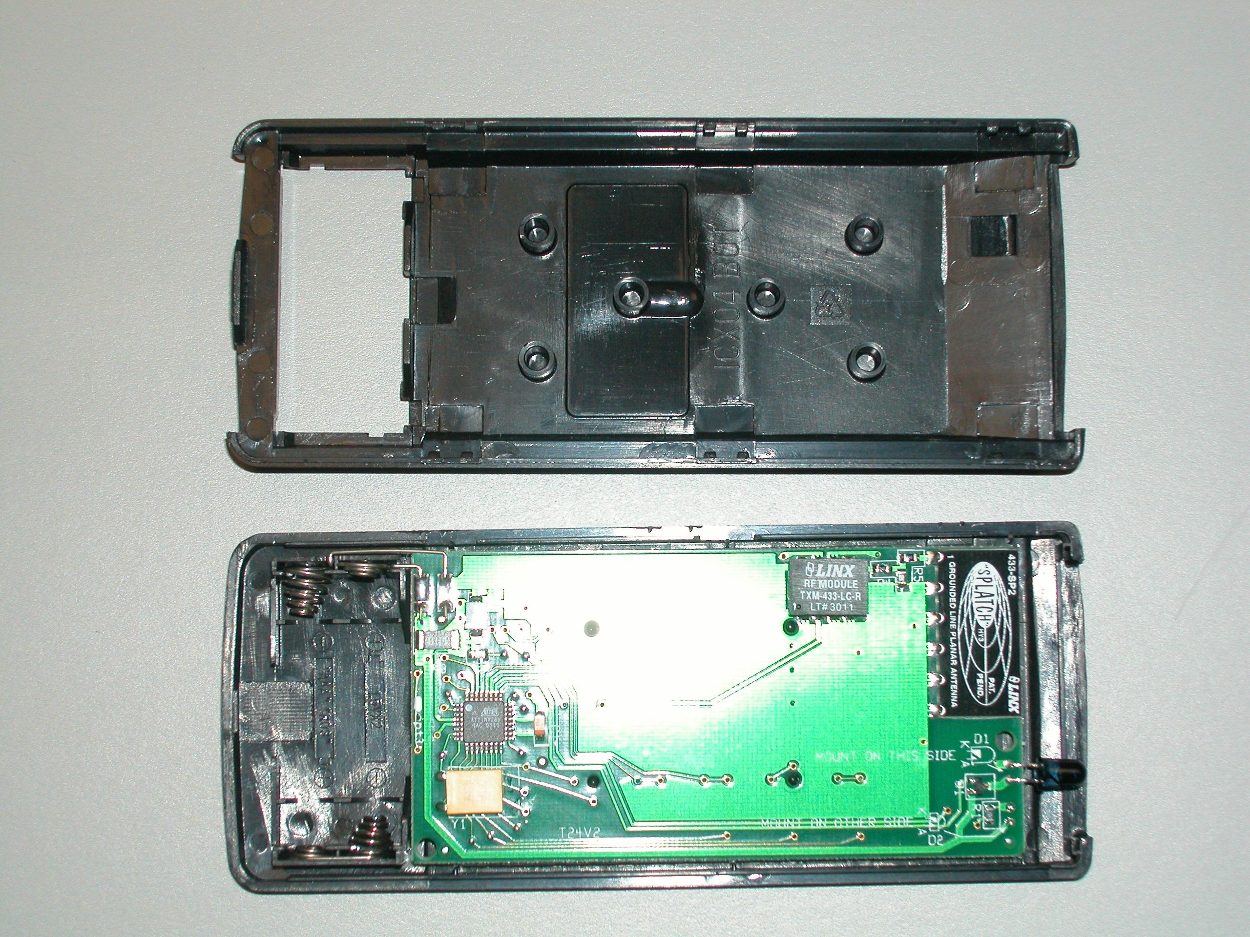
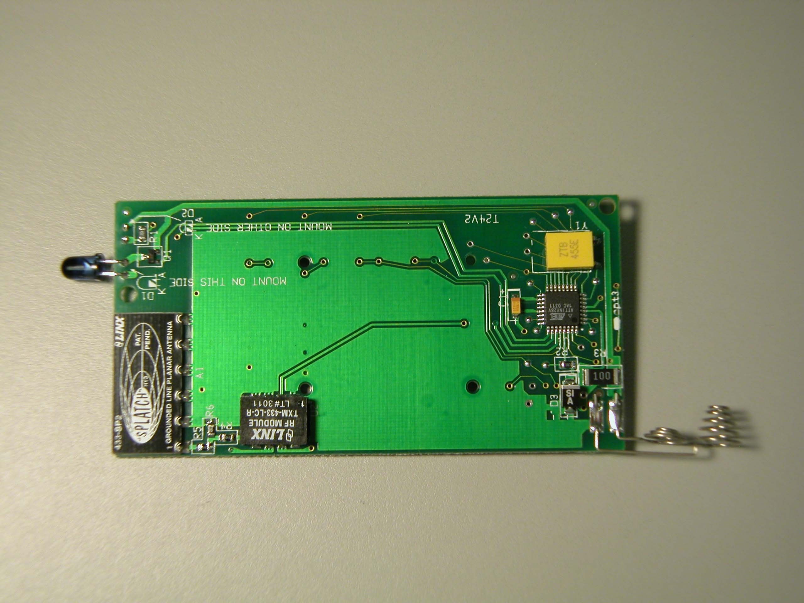
From: Todd Seeley [[email protected]] Sent: Tuesday, March 23, 2004 1:57 PM To: [email protected] Cc: 'Todd Seeley' Subject: RE: Non-Conformities FCC ID: P7RT24AP433 (Ref # E04-000020-1) Importance: High Randy: Thanks for getting this done. Please see my comments below and update the filing accordingly. Thanks, Todd Seeley Principal Engineer Direct Phone: (303) 402-5272 Email: [email protected] CONFIDENTIALITY NOTICE: ATTENTION! This electronic mail and any attachments contain information which is the property of the sender and which may be confidential and legally privileged. The information in this transmission is intended ONLY for the use of the person or entity to whom the electronic mail was sent, as indicated within the body of the message, above. If you are not the intended recipient, any disclosure, copying, distribution, dissemination, or action taken in reliance on the contents of the information contained in this transmission is strictly prohibited. If you have received this Transmission in error, please call this office collect at 303-786-7999 to let us know and delete all copies of this message immediately. Thank you. -----Original Message----- From: [email protected] [mailto:[email protected]] Sent: Tuesday, March 23, 2004 12:53 PM To: [email protected] Subject: Non-Conformities FCC ID: P7RT24AP433 (Ref # E04-000020-1) Non-Conformities FCC ID: P7RT24AP433 (Ref # E04-000020-1) Item 1. Since form 731 does not list the equipment specifications, the information was gathered from test report. Please verify the frequency range or ranges of the device. +++++++++++++Equipment tested to 15.231 the device operates at the +++++++++++++discrete fundamental freq of 434MHz the fundamental. ++++++++++++++++++ Item 2. Since duty cycle correction factor was used to demonstrate compliance, please supply the calculations and data used to determine the pulse averaging per 15.35(c), "The exact method of calculating the average field strength shall be submitted with any application for certification." +++++++++++++++ Please review page 13 of the report +++++++++++++++ +++++++++++++++++++++++ Item 3. No information is given in the test report regarding exploratory maximization of the EUT signals in three orthogonal orientations per ANSI C63.4 Section 12.1.4.1, ".In addition, exploratory radiated emissions testing of hand- held or body-worn devices shall include rotation of the EUT through three orthogonal axes to determine the attitude that maximizes the emissions. This equipment arrangement shall be used in final measurements of radiated emission from the EUT." Please clarify if exploratory measurements were performed in three orthogonal orientations and if the final data represents the worst case of emissions. +++++++++++++++ please review page 5 of the report +++++++++++++++++++ Item 4. 2.1033(b)(4): The operational description needs to include a description of the RF circuitry and a detailed description of the carrier operation including the grounding system and the integral antenna. Please supply an updated operational description. +++++++++++ Client has been informed and is working on the update. It +++++++++++ will be provided shortly. +++++++++++++++ Item 5. 2.1033(b)(7): Internal photos are inadequate for showing component placement, one photo is over-exposed and the other is out of focus. Primarily, additional photos need only to be taken of the component side of the PCB to clearly show all components and layout. +++++++++++++ a New photo has been taken and attached. Please update the filing with this photo. ++++++++++++++++++++++++++++++++++++++ The items indicated above must be submitted before processing can continue on the referenced application. Failure to provide the requested information within 60 days may result in application dismissal pursuant to Section 2.917(c) and forfeiture of the filing fee pursuant to Section 1.1106. All Best, Randal Clark CKC Certification Services.
ID Label/Location Info
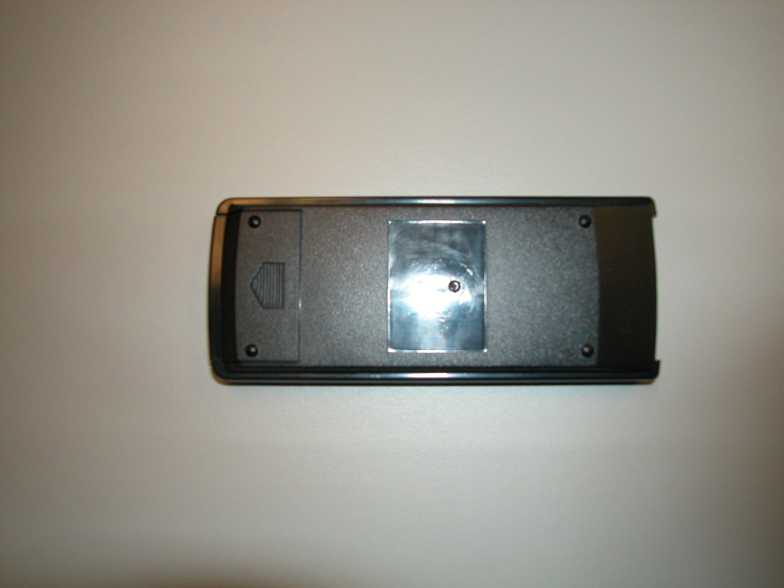
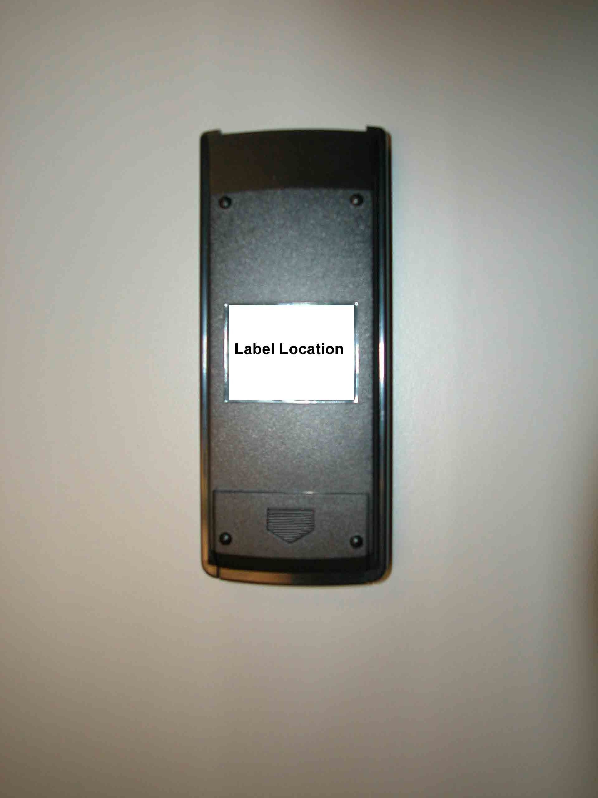
FCCID:P7RT24AP433 ThisdevicecomplieswithPart15oftheFCCRules. Operationissubjecttothefollowingtwoconditions: (1)Thisdevicemaynotcauseharmfulinterferenceand (2)thisdevicemustacceptanyinterferencereceived, includinginterferencethatmaycauseundesiredoperation. ThisClassBdigitalapparatusmeetsallrequirements oftheCanadianInterference-CausingEquipment Regulations. 1.5” Labeltextis5point,ArialNarrow Whitelettersonblackbackground labelappliedtocenterofbackofTransmitter
Operational Description
Description of the T24A-Pdual433 Transmitter The T24A-Pdual433 transmitter operates at 433.92 MHz ± 75 KHz. The transmitter has different buttons that correspond to the different channels controlled by the receiver. Pressing button 1 causes the receiver to accept commands for the unit connected to channel l. Pressing button 2 causes the receiver to accept commands for the unit connected to channel 2. The receiver knows what channel to operate by the recognition code sent by the transmitter. Please note the transmitter only operates at 433.92 MHz, it is the recognition code sent by the transmitter that determines what channel the receiver will operate. The RF section of this board is simply a Linx brand transmitter module connected to a Linx brand surface mount style antenna via a T pad to set the appropriate output power level. The circuit board is double sided rigid, .062” thick FR4 material, with as much of the spare space filled with ground plane as possible. The transmitted RF “codes” are on off keying (OOK) similar to the sequence used by Linx brand handheld transmitters. The worst case on time over any 100ms interval is 45%.
Test Report
EMC EMISSIONS - TEST REPORT (Full) Test Report No. BC400127 -3 Issue Date: Friday, February 6, 2004 Model / Serial No. T24A / SN: EMC1 Product Type IR and RF Transmitter Client Electronic Solutions, Inc. Manufacturer Electronic Solutions, Inc. License holder Electronic Solutions, Inc. 11811 Upham Street Address Broomfield, CO 80020 Test Criteria Applied FCC CFR47 Part 15.231 Test Result PASS Test Project Number References BC400127-1 Total Pages Including Appendices: 26 Title 47 CFR 15.231: RADIO FREQUENCY DEVICES operating in the frequency range of 40.66-40.70MHz and above 70MHz (including 15.205, 15.207, 15.209 where applicable) Reviewed By : Approved By : INTERNATIONAL APPROVALS LABORATORIES (IAL) reports apply only to the specific samples tested under stated test conditions. It is the manufacturer's responsibility to assure that additional production units of this model are manufactured with identical electrical and mechanical components. IAL have no liability for any deductions, inferences or generalizations drawn by the client or others from IAL issued reports. This report is the confidential property of the client. As a mutual protection to our clients, the public and ourselves, extracts from the test report shall not be reproduced except in full without our written approval of IAL. This report shall not be used by the client to claim product endorsement by NVLAP (No. 200624- 0) or any agency of the US government. International Approval Laboratories and its professional staff hold government and professional organization certifications and are members of IEEE, NVLAP, and VCCI. Project File: BC400127-1 Page 2 of 26 International Approvals Laboratories, LLC 5541 Central Avenue, Suite 110 Boulder, Colorado 80301 Voice: 303 786 7999 Fax: 303 449 6160 Rev.No 1 D I R E C T O R Y Documentation Page(s) Test report 1 - 9 Directory 2 Test Regulations 3-4 General Remarks 5-6 Test-setup Photographs 6-9 Appendix A Test Data Sheets and Test Equipment Used 10 - 20 Appendix B Test Plan/Constructional Data Form 21 - 21 Appendix C Measurement Protocol/Test Procedures 22 - 26 STATEMENT OF MEASUREMENT UNCERTAINTY The data and results referenced in this document are true and accurate. The measurement uncertainty for Conducted Emissions in the frequency range of 150kHz – 30MHz is calculated to be ±2.30dB and for Radiated Emissions is calculated to be ±3.60dB in the frequency range of 30MHz – 200MHz and ±3.38dB in the frequency range of 200MHz – 1000MHz. EUT Received Date: 26-Jan -2004 Testing Start Date: 26-Jan -2004 Testing End Date: 26-Jan -2004 Project File: BC400127-1 Page 3 of 26 International Approvals Laboratories, LLC 5541 Central Avenue, Suite 110 Boulder, Colorado 80301 Voice: 303 786 7999 Fax: 303 449 6160 Rev.No 1 The tests were performed according to following regulations : 1. FCC CFR47 Part 15.205 2. FCC CFR47 Part 15.207 3. FCC CFR47 Part 15.209 4. FCC CFR47 Part 15.231 5. ICES-003 Emission Test Results: Conducted Emissions, Powerline (15.207) - Not Applicable Test Result Minimum limit margin dB at MHz Maximum limit exceeding dB at MHz Remarks: Battery Powered Device Radiated Emissions (15.209) / 15.231(b)(3) - PASS Test Result Minimum limit margin -26.0 dB at 195.0 MHz Maximum limit exceeding dB at MHz Remarks: Radiated Emissions (15.205) / 15.231(b)(2) - PASS Test Result Minimum limit margin -16.31 dB at 1301.85 MHz Maximum limit exceeding dB at MHz Remarks: Radiated Emissions 15.231(a)(1)&(2) - PASS Test Result Remarks: Required measurement for manually and automatic operated transmitter equipment. <5 Sec. after activation Radiated Emissions 15.231(b)(1) - PASS Test Result Minimum limit margin -1.96 dB at 433.99 MHz Maximum limit exceeding dB at MHz Remarks: Measurements were taken utilizing the methods dictated by Part 15.35 for averaging pulsed emissions and for limiting peak emissions Project File: BC400127-1 Page 4 of 26 International Approvals Laboratories, LLC 5541 Central Avenue, Suite 110 Boulder, Colorado 80301 Voice: 303 786 7999 Fax: 303 449 6160 Rev.No 1 Radiated Emissions 15.231(c) - PASS Test Result 0.98MHz Remarks: Devices operated within the frequency band of 70 – 900MHz: -20dBc Bandwidth maximum of 0.25% of the center frequency Devices operated within the frequency band of >900MHz: -20dBc Bandwidth maximum of 0.50% of the center frequency Radiated Emissions 15.231(d) - Not Applicable Test Result Remarks: Devices operated within the frequency band of 40.66 – 40.70MHz: -20dBc Bandwidth maximum of 0.01% of the center frequency as measured through the temp range of -20 to +50 deg. C, and at 85 - 115% of the nominal supply voltage at 20 deg. C “a new battery would be used in cases where the device is powered from a battery” Radiated Emissions 15.231(e) - Not Applicable Test Result Minimum limit margin 00.00 dB at 0000.00 MHz Maximum limit exceeding dB at MHz Remarks: Measurements were taken utilizing the methods dictated by Part 15.35 for averaging pulsed emissions and for limiting peak emissions Project File: BC400127-1 Page 5 of 26 International Approvals Laboratories, LLC 5541 Central Avenue, Suite 110 Boulder, Colorado 80301 Voice: 303 786 7999 Fax: 303 449 6160 Rev.No 1 GENERAL REMARKS: Testing was performed in 3 different orthoganal axis to determine the worste case emissions from the device. The worste case emissions measurements are shown in this report. In any case where the device is powered off a battery, a fresh battery was used durring test. In cases where the device is powered off an AC supply, voltage was veried per Part 15.31 to find worst case emissions. Modifications required to pass: NONE Test Specification Deviations: NONE Project File: BC400127-1 Page 6 of 26 International Approvals Laboratories, LLC 5541 Central Avenue, Suite 110 Boulder, Colorado 80301 Voice: 303 786 7999 Fax: 303 449 6160 Rev.No 1 Required Information In Accordance to FCC CFR 47 Part 2.1033: Exhibits Including (where applicable): 1. Users Manual 2. Operation Description 3. Block Diag…
Text truncated - open the document above for the full version.
Test Report
3/25/04 Electronic Solutions, Inc. 11811 Upham St. Unit #2, Broomfield, CO 80020-2710 voice: 303-469-9322 fax: 303-469-5129 www.elec-solutions.com Duty Cycle for T24A-Pdual433 Transmitter A packet of data consists of the start sequence, 20 address bits, and 16 data bits. The packet is compatible with the Holtek brand of data encoder chips used in Linx brand transmitters and other places. The packet sequence uses the following definitions: The Start sequence consists of: 471μs on, 471μs off, 973μs on, 973μs off, 471μs on, 471μs off, 973μs on, 973μs off, 471μs on (3 1’s and 2 0’s) Address & data bits consist of: a “0 bit” being defined as 471μs off, 973μs on, a “1 bit” being defined as 973μs off, 471μs on. The start sequence consists of 2 0’s + 3 1’s. The address consists of 20 bits and the worst case on time is 16 0’s + 4 1’s. The data consists of 16 bits and the worst case on time is 7 0’s + 9 1’s. There is a pause of at least 21.3 msec before the packet is transmitted again. The packet period is 78.33 msec. Over a 100 ms interval, the worst case starts the interval at the beginning of the start sequence and ends 21.67 msec into the next packet (10 bits into the address) = {[(2+16+7)*973 + (3+4+9)*471] + [3*471 + 12*973]} / 100,000 = 44.95%
Contact Information
Applicant
Brian Hodd(engineering manager)
Technical Contact
Electronic Solutions Inc.Gary Skinner
[email protected]303-469-9322
11811 Upham Street · Broomfield, Colorado · United States
Non-Technical Contact
Electronic Solutions Inc.Gary Skinner
[email protected]303-469-9322
Test Firm
International Approval Laboratories, LLCTodd Seeley
Technical Specifications
| # | Rule Parts | Frequency Range | Power Output |
|---|---|---|---|
| 1 | 15.231 | 433.92 MHz - 433.92 MHz | - |
Other Applications from Electronic Solutions, Inc.
P7RRFRQTRANS
Feb 13, 2013Remote Control
Equipment Class
DTS - Digital Transmission System
P7RRFSWTINTRFC
Sep 17, 2012Remote Control
Equipment Class
DTS - Digital Transmission System
P7RSTE1
Dec 29, 2011Remote Control
Equipment Class
DTS - Digital Transmission System
P7RM4E1
Apr 07, 2011Drapery Motor & Control
Equipment Class
DTS - Digital Transmission System
P7RZWRQREC
Mar 26, 2010Z-Wave dongle control
Equipment Class
DXX - Part 15 Low Power Communication Device Transmitter