P7RT24APDUALRemote Control - Transmitter
Electronic Solutions, Inc.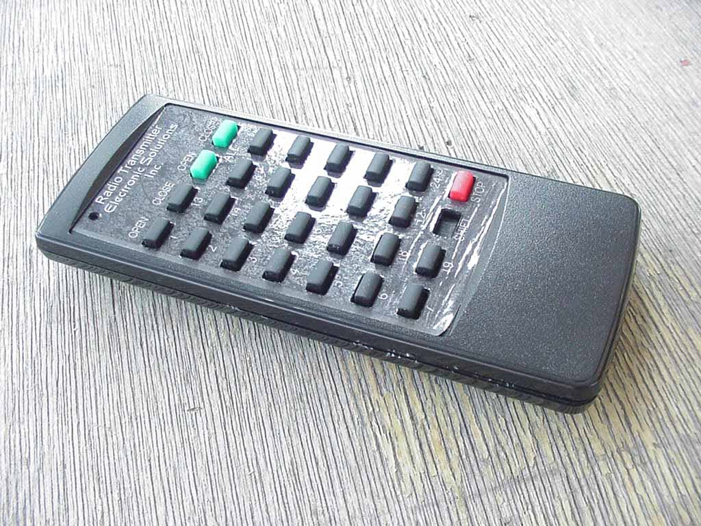
Click to zoom
Application Details
- Equipment Class
- DSC - Part 15 Security/Remote Control Transmitter
- Date of Grant
- Mar 26, 2002
- Application Purpose
- Original Equipment
- Date of Application
- Mar 26, 2002
- Equipment Note
- Remote Control - Transmitter
- Frequency Range
- 418.00000000 - 418.00000000
- Company
- Electronic Solutions, Inc.
- Country
- United States
Documents & Files
Document Text
Text extracted from the exhibit documents filed with the FCC. Open a document above to read the original.
Users Manual
3/7/02 Electronic Solutions, Inc.Electronic Solutions, Inc. 11811 Upham St. Unit #2, Broomfield, CO 80020-2710 voice: 303-469-9322 fax: 303-469-5129 www.elec-solutions.com Electronic Solutions, Inc. T24A-Pdual with RR24 connected to RP24 Operation & Installation Manual March 7, 2002 Specifications: T24A-Pdual Transmitter Power Supply Voltage 3V (2 AAA batteries) Frequency 418 MHz RR24 Receiver Power Supply Voltage 5V (provided via RP24) 3/7/02 Electronic Solutions, Inc.Electronic Solutions, Inc. 11811 Upham St. Unit #2, Broomfield, CO 80020-2710 voice: 303-469-9322 fax: 303-469-5129 www.elec-solutions.com RR24 Installation GuideRR24 Installation Guide Connect the RR24 Radio Receiver to the RP24 as shown The RR24 unit must connect to an Eye Jack on a RP24 or splitter. If the eye connects to a splitter, then the Main jack next to it must connect to the Eye Jack on an RP24. For best reception, the RR24 should be mounted with the antenna pointing up, and it should not be placed on or near a metal surface. The RR24 unit can learn up to 5 different transmitters to work with. It ships from the factory with NO transmitters learned, you must train it in the field to work with your specific transmitters. Press and release the “Learn Transmitter” button on the RR24, the red LED will come on if 5 transmitters have not already been learned, the unit is now ready to learn another radio transmitter: Press stop on the radio transmitter, (buttons other than stop are ignored) The LED on the RR24 will go out, this transmitter is added to the list of known transmitters, the RR24 is now operating normally again. Note that if this transmitter is already known, this button will be ignored and the LED will remain lit. If no stop command is received within 10 seconds, the red LED will flash off, then on, and then go out. NO new transmitters were learned! (Note that if no transmitters are known at all, then the LED will turn back on immediately) If the red LED is on and the learn button is pressed and released, the red LED will turn off with no changes to the learned list. (Note that if no transmitters are known at all, then the LED will turn back on immediately) If no transmitters are known, (as shipped from factory) then the red LED will turn on as soon as the unit is plugged in. Note that the LED will flash every 10 seconds until a transmitter is learned. Pressing the learn button has no meaning while in this mode (the LED will turn off while the button is pushed). Press and hold the learn button for 5 seconds to clear all known transmitters, (the LED will blink on and off.) Release the button, the red LED will come on, and the unit is ready to learn the 1 st transmitter. 3/7/02 Electronic Solutions, Inc.Electronic Solutions, Inc. 11811 Upham St. Unit #2, Broomfield, CO 80020-2710 voice: 303-469-9322 fax: 303-469-5129 www.elec-solutions.com If you press and release the learn button and the LED does not come on, the list is “full” and no more transmitters can be learned. Note that in the learn mode (button is pressed or the LED is on), the receiver is not passing commands to the RP24 system. Once the transmitter is learned, and if the STOP button is still held, the stop command will be sent to the system. INSTRUCTION TO THE USER This equipment has been tested and found to comply with the limits for a class B digital device, pursuant to part 15 of the FCC Rules. These limits are designed to provide reasonable protection against harmful interference in a residential installation. This equipment generates, uses and can radiate radio frequency energy and if not installed and used in accordance with the instructions, may cause harmful interference to radio communications. However, there is no guarantee that interference will not occur in a particular installation. If this equipment does cause harmful interference to radio or television reception, which can be determined by turning the equipment off and on, the user is encouraged to try to correct the interference by one or more of the following measures: * Reorient or relocate the receiving antenna. * Increase the separation between the equipment and receiver. * Connect the equipment into an outlet on a circuit different from that to which the receiver is connected. * Consult the dealer or an experienced radio/TV technician for help. The user is cautioned that change and modifications made to the equipment without the approval of manufacturer could void the user's authority to operate this equipment.
Attestation Statements
11811 Upham St. Unit #2, Broomfield, CO 80020-2710 303-469-9322 fax 303-469-5129 March 5, 2002 Federal Communications Commission 7435 Oakland Mills Road Columbia, Maryland 2l046 Subject: Modification to the T12A-Pdual Transmitter Gentlemen: To successfully meet the radiated emission requirement of FCC Part 15.231, it was necessary to add an attenuation pad between the RF out on the RF Module and the antenna. The attenuation pad is as follows: R4 = 20 ohms R5 = 20 ohms R6 = 47 ohms This exact modification will be implemented and incorporated into our schematics and printed circuit board layout and will be contained in production devices when the product is released. If you have any further questions or need additional information, please feel free to give me a call at 303-465-1229 or 303-469-9322. Sincerely, Gary F. Skinner, President, Electronic Solutions, Inc.
Cover Letter(s)
114 OLINDA DRIVE • •• • BREA, CALIFORNIA 92823 • •• • (714) 579-0500 • •• • FAX (714) 579-1850 1 March 4, 2002 Compatible Electronics TCB 114 Olinda Drive Brea, CA 92823 Subject: Request for Certification of the Electronic Solutions, Inc.. Remote Control – Transmitter P/N: T24A-Pdual FCC ID: P7RT24APDUAL Gentlemen: We have enclosed a package for the certification of the Electronic Solutions, Inc. Remote Control – Transmitter P/N: T24A-Pdual. We have enclosed the completed Form 731 with the applicable exhibits. If you have any questions or need any additional information, please give me a call at (714) 579-0500. Sincerely, Kyle Fujimoto Test Engineer
Cover Letter(s)
1 Scott McCutchan From: Scott McCutchan [[email protected]] Sent: Monday, March 18, 2002 9:50 AM To: [email protected] Subject: FCC ID: P7RT24APDUAL Scott McCutchan.vcf In order for processing of this application (FCC ID: P7RT24APDUAL) to continue, the following issue(s) will have to be addressed: 1) The test report states that no modifications were performed on the device under test. However, there is a modification letter from the manufacturer stating that modifications were performed. Which is correct? 2) According to the expository statement, the device can operate on one of 24 channels. In the test report, only one channel was tested. Please explain. Correpondence to this request may be submitted on our web site under confirmation number P7RT24APDUAL-1. The item(s) indicated above must be submitted before processing can continue on the above referenced application. Failure to provide the requested information within 60 days of the original e-mail date may result in application dismissal and forfeiture of the filing fee. Also, please note that partial responses increase processing time and should not be submitted. Any questions about the content of this correspondence should be directed to [email protected]. If you have any questions, feel free to contact me. Best regards, Scott McCutchan Lab Manager Compatible Electronics, Brea Division (714) 579-1489 fax (714) 579-1850 http://www.celectronics.com
Cover Letter(s)
Correspondence by Project Project Number: 1439026345 Correspondence Number Memo P7RT24APDUAL-1 1) The test report states that no modifications were performed on the device under test. However, there is a modification letter from the manufacturer stating that modifications were performed. Which is correct? The test report has been revised to show that there was a modification during the testing. The test report will now reflect what the modification letter states. 2) According to the expository statement, the device can operate on one of 24 channels. In the test report, only one channel was tested. Please explain. Please see the explanation on how the transmitter works. This will be uploaded in the exhibits. To summarize, the transmitter only operates on 1 frequency (418 MHz), but uses different recognition codes to tell the receiver what channel to activate.
ID Label/Location Info
FCCID:P7RT24APDUAL ThisdevicecomplieswithPart15oftheFCCRules. Operationissubjecttothefollowingtwoconditions: (1)Thisdevicemaynotcauseharmfulinterferenceand (2)thisdevicemustacceptanyinterferencereceived, includinginterferencethatmaycauseundesiredoperation. ThisClassBdigitalapparatusmeetsallrequirements oftheCanadianInterference-CausingEquipment Regulations. 1.5” Labeltextis5point,ArialNarrow Whitelettersonblackbackground labelappliedtocenterofbackofT24A-Pdual
Operational Description
Description of T24A-Pdual Controlling RR24 & RP24AU The RR24 receiver connects to the RP24AU via 4 conductor modular cable. The RP24AU connects 115VAC power to a 4 wire motor via the 6-wide spring-loaded power connector. This same connector is used to apply power to the RP24AU. The typical motor being controlled will have 2 windings and a start capacitor between them. Applying power on one winding will cause the motor to spin in a direction that will open a window covering. Applying power to the other winding will cause the motor to close. The motor has built in mechanical limit switches to stop the motor at the fully open and fully closed positions. Each RP24AU operates on one of 24 “channels” to allow multiple motors to be controlled independently. The hand held transmitter can send open and close commands for all 24 channels. Plus it has specific buttons for running all motors at once and stopping all motors. Pushing either open or close button turns power on in the appropriate direction for 3 minutes. Another push of either button, or the STOP button, causes the motor to stop. In either mode, once the motor is running, power is applied for 3 minutes, even though the motor may finish moving before this time is up. During this time, 2 button pushes are required to start the motor because the 1st button push is seen as a stop. Manual switches may also be used to control the motor, and are connected to the small screw terminals on the RP24AU. The RP24AU is designed to receive a command sequence from an infrared “eye”. The RR24 accepts radio commands and converts them into the appropriate IR command. This conversion is needed because radio commands must have an address associated with them so different controls can be used in different parts of a house controlling different motors. With IR this is easily accomplished as IR does not pass through walls.
Operational Description
DESCRIPTION OF HOW THE T24A-Pdual TRANSMITTER OPERATES The T24A-Pdual transmitter operates at 418 MHz. The transmitter has different buttons that correspond to the different channels controlled by the receiver. Pressing button 1 causes the receiver to accept commands for the unit connected to channel 1. Pressing button 2 causes the receiver to accept commands for the unit connected to channel 2. The receiver knows what channel to operate by the recognition code sent by the transmitter. Please note the transmitter only operates at 418 MHz, it is the recognition code sent by the transmitter that determines what channel the receiver will operate.
Test Report
FCC ID: P7RT24APDUAL Report No.: B20301D1 114 OLINDA DRIVE, BREA, CALIFORNIA 92823 PHONE: (714) 579-0500 FAX: (714) 579-1850 Page 1 of 16 FCC PART 15, SUBPART C TEST REPORT for REMOTE CONTROL – TRANSMITTER P/N: T24A-Pdual Prepared for ELECTRONIC SOLUTIONS, INC. 11811 UPHAM STREET, UNIT #2 BROOMFIELD, COLORADO 80020 Prepared by:_____________________ KYLE FUJIMOTO Approved by:____________________ MICHAEL CHRISTENSEN COMPATIBLE ELECTRONICS INC. 114 OLINDA DRIVE BREA, CALIFORNIA 92823 (714) 579-0500 DATE: MARCH 1, 2002 REPORT APPENDICES TOTAL BODY A B C D E PAGES 16 2 2 11 15 2 48 This report shall not be reproduced except in full, without the written approval of Compatible Electronics. FCC ID: P7RT24APDUAL Report No.: B20301D1 114 OLINDA DRIVE, BREA, CALIFORNIA 92823 PHONE: (714) 579-0500 FAX: (714) 579-1850 Page 2 of 16 TABLE OF CONTENTS Section / Title PAGE GENERAL REPORT SUMMARY 4 SUMMARY OF TEST RESULTS 4 1. PURPOSE 5 2. ADMINISTRATIVE DATA 6 2.1 Location of Testing 6 2.2 Traceability Statement 6 2.3 Cognizant Personnel 6 2.4 Date Test Sample was Received 6 2.5 Disposition of the Test Sample 6 2.6 Abbreviations and Acronyms 6 3. APPLICABLE DOCUMENTS 7 4. Description of Test Configuration 8 4.1 Description of Test Configuration - EMI 8 4.1.1 Cable Construction and Termination 9 5. LISTS OF EUT, ACCESSORIES AND TEST EQUIPMENT 10 5.1 EUT and Accessory List 10 5.2 EMI Test Equipment 11 6. TEST SITE DESCRIPTION 12 6.1 Test Facility Description 12 6.2 EUT Mounting, Bonding and Grounding 12 7. Test Procedures 13 7.1 Radiated Emissions (Spurious and Harmonics) Test 13 7.2 Band Edge Plots of the Low and High Channels 15 8. CONCLUSIONS 16 FCC ID: P7RT24APDUAL Report No.: B20301D1 114 OLINDA DRIVE, BREA, CALIFORNIA 92823 PHONE: (714) 579-0500 FAX: (714) 579-1850 Page 3 of 16 LIST OF APPENDICES APPENDIX TITLE A Modifications to the EUT B Additional Models Covered Under This Report C Diagrams, Charts and Photos • Test Setup Diagrams • Radiated Emissions Photos • Antenna and Effective Gain Factors D Data Sheets E Laboratory Recognitions LIST OF FIGURES FIGURE TITLE 1 Conducted Emissions Test Setup 2 Plot Map And Layout of Test Site FCC ID: P7RT24APDUAL Report No.: B20301D1 114 OLINDA DRIVE, BREA, CALIFORNIA 92823 PHONE: (714) 579-0500 FAX: (714) 579-1850 Page 4 of 16 GENERAL REPORT SUMMARY This electromagnetic emission test report is generated by Compatible Electronics Inc., which is an independent testing and consulting firm. The test report is based on testing performed by Compatible Electronics personnel according to the measurement procedures described in the test specifications given below and in the "Test Procedures" section of this report. The measurement data and conclusions appearing herein relate only to the sample tested and this report may not be reproduced without the written permission of Compatible Electronics, unless done so in full. This report must not be used to claim product endorsement by NVLAP or any other agency of the U.S. Government. Device Tested: Remote Control – Transmitter P/N: T24A-Pdual S/N: N/A Product Description: See Expository Statement. Modifications: The EUT was modified during the testing. Please see the list located in Appendix A. Manufacturer: Electronic Solutions, Inc. 11811 Upham Street, Unit #2 Broomfield, Colorado 80020 Test Date: March 1, 2002 Test Specifications : EMI requirements CFR Title 47, Part 15 Subpart C, Sections 15.205 and 15.231 Test Procedure: ANSI C63.4: 1992 Test Deviations: The test procedure was not deviated from during the testing. SUMMARY OF TEST RESULTS TEST DESCRIPTION RESULTS 1 Conducted RF Emissions, 450 kHz - 30 MHz The EUT operates on two 1.5 volt batteries only and cannot be plugged into the AC public mains. Therefore, this test was not performed. 2 Radiated RF Emissions, 10 kHz - 4200 MHz Complies with the limits of CFR Title 47, Part 15, Subpart C, sections 15.205, 15.209, and 15.231 FCC ID: P7RT24APDUAL Report No.: B20301D1 114 OLINDA DRIVE, BREA, CALIFORNIA 92823 PHONE: (714) 579-0500 FAX: (714) 579-1850 Page 5 of 16 1. PURPOSE This document is a qualification test report based on the Electromagnetic Interference (EMI) tests performed on the Remote Control – Transmitter P/N: T24A-Pdual. The EMI measurements were performed according to the measurement procedure described in ANSI C63.4: 1992. The tests were performed in order to determine whether the electromagnetic emissions from the equipment under test, referred to as EUT hereafter, are within the specification limits defined by CFR Title 47, Part 15, Subpart C, sections 15.205, 15.209, and 15.231. FCC ID: P7RT24APDUAL Report No.: B20301D1 114 OLINDA DRIVE, BREA, CALIFORNIA 92823 PHONE: (714) 579-0500 FAX: (714) 579-1850 Page 6 of 16 2. ADMINISTRATIVE DATA 2.1 Location of Testing The EMI tests described herein were performed at the test facility of Compatible Electronics, 114 Olinda Drive, Brea, California 92823. 2.2 Traceability Statement The calibration certificates of all test equipment used during the test are on file at the location of the test. The calibration is traceable to the National Institute of Standards and Technology (NIST) . 2.3 Cognizant Personnel Electronic Solutions, Inc. Gary Skinner President Compatible Electronics Inc. Kyle Fujimoto Test Engineer Michael Christensen Test Engineer 2.4 Date Test Sample was Received The test sample was received on February 16, 2002. 2.5 Disposition of the Test Sample The test sample has not been returned to Electronic Solutions, Inc. as of March 1, 2002. 2.6 Abbreviations and Acronyms The following abbreviations and acronyms may be used in this document. RF Radio Frequency EMI Electromagnetic Interference EUT Equipment Under Test P/N Part Number S/N Serial Number HP Hewlett Packard ITE Information Technology Equipment CML Corrected Meter Limit LISN Line Impedance Stabilization Network FCC ID: P7RT24APDUAL Report No.: B20301D1 114 OLINDA DRIVE, BREA, CALIFORNIA 92823 PHONE: (714) 579-0500 FAX: (714) 579-1850 Page 7 of 16 3. …
Text truncated - open the document above for the full version.
Contact Information
Applicant
Brian Hodd(engineering manager)
Technical Contact
Compatible ElectronicsKyle Fujimoto
[email protected]714-579-0500
114 Olinda Drive · Brea, California · United States
Test Firm
Compatible ElectronicsScott McCutchan
714-579-0500Fax: 714-579-1850
Technical Specifications
| # | Rule Parts | Frequency Range | Power Output |
|---|---|---|---|
| 1 | 15.231 | 418 MHz - 418 MHz | - |
Other Applications from Electronic Solutions, Inc.
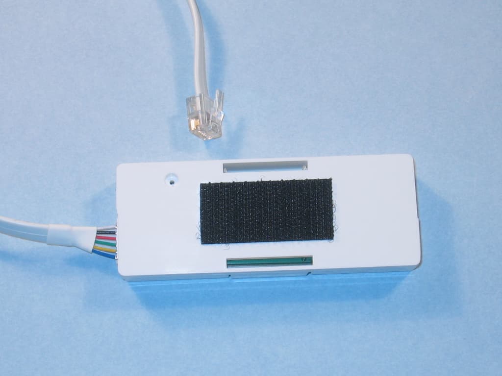
P7RRFRQTRANS
Feb 13, 2013Remote Control
Equipment Class
DTS - Digital Transmission System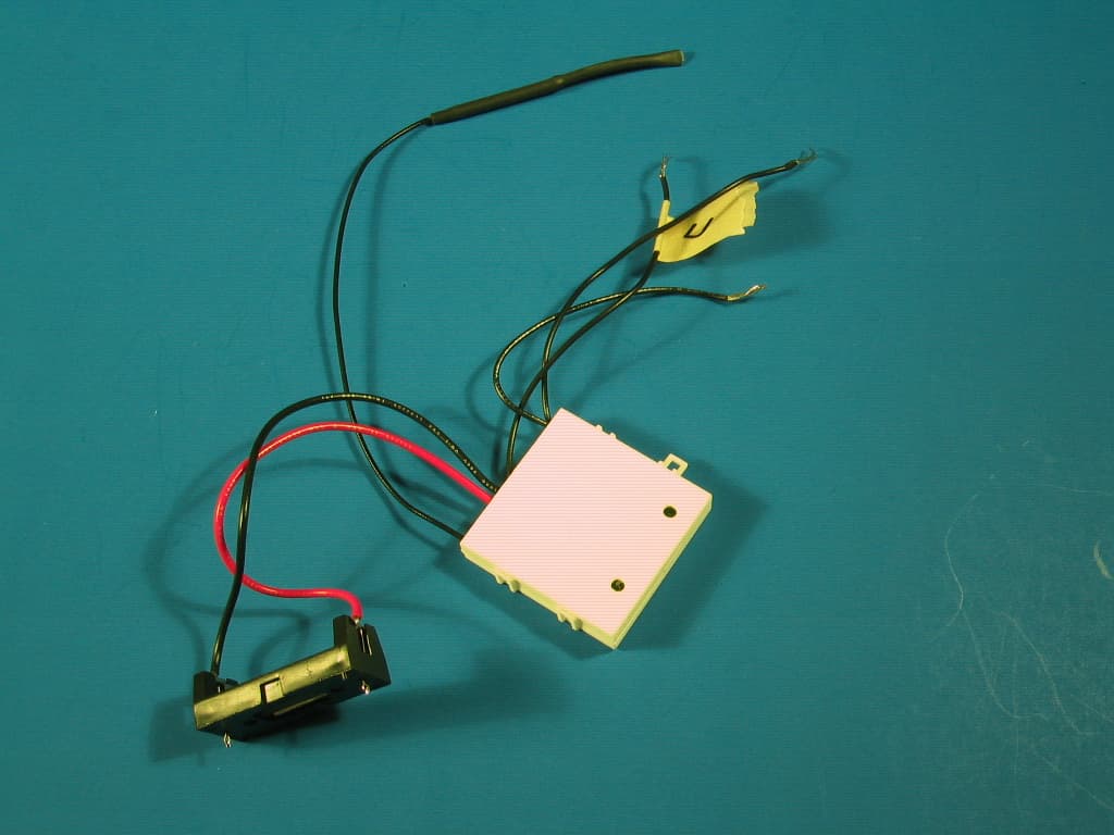
P7RRFSWTINTRFC
Sep 17, 2012Remote Control
Equipment Class
DTS - Digital Transmission System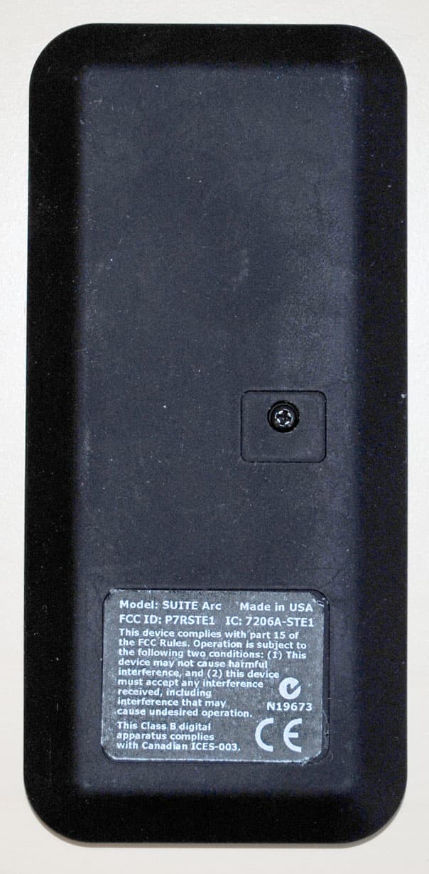
P7RSTE1
Dec 29, 2011Remote Control
Equipment Class
DTS - Digital Transmission System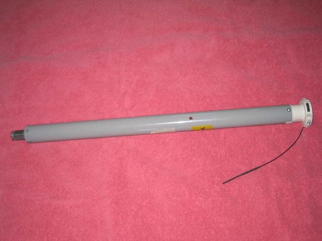
P7RM4E1
Apr 07, 2011Drapery Motor & Control
Equipment Class
DTS - Digital Transmission System
P7RZWRQREC
Mar 26, 2010Z-Wave dongle control
Equipment Class
DXX - Part 15 Low Power Communication Device Transmitter