P9M-AIONTXPhottix Aion Wireless Timer Remote Transmitter
Phottix (HK) Ltd.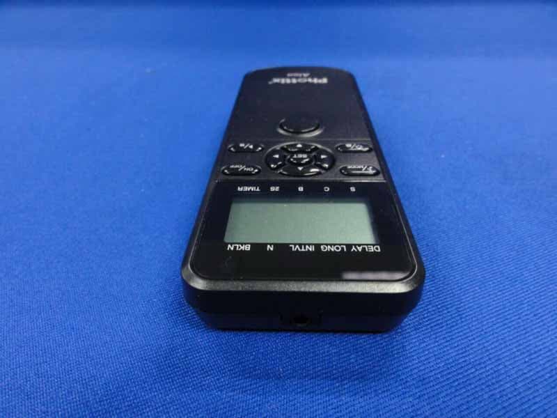
Click to zoom
Application Details
- Equipment Class
- DXX - Part 15 Low Power Communication Device Transmitter
- Date of Grant
- Jun 03, 2013
- Application Purpose
- Original Equipment
- Date of Application
- Jun 03, 2013
- Equipment Note
- Phottix Aion Wireless Timer Remote Transmitter
- Frequency Range
- 2432.00000000 - 2439.00000000
- Company
- Phottix (HK) Ltd.
- Country
- China
Documents & Files
Document Text
Text extracted from the exhibit documents filed with the FCC. Open a document above to read the original.
Users Manual
1 10 18 26 34 42 50 57 1 Phottix Aion Wireless Timer Instructions Parts Timer 1. Cable Port 2. Function LED 3. LCD Display 4. Sound / Mode Button 5. Backlight / Lock Button 6. Power Button 7. Play / Stop Button 8. Set Button 9. Adjustment buttons 10. Shutter Button 11. Battery Door Receiver 1. Cable Port 2. Function LED 3. Power Button 4. Cold Shoe 5. 3/16 Mounting Lug 6. Locking Ring 7. Battery Door 2 The Phottix Aion Wireless Timer and Shutter release will work as a wired or wireless timer and remote shutter release system. Tip: Turn off all devices – cameras, and Phottix Aion Timers or Receivers - when connecting and disconnecting devices. Inserting batteries in Timer and Receiver 1. Press the battery cover in while pushing it away from the timer or Receiver. The battery cover will slide open. 2. Remove the battery cover. 3. Insert AAA batteries. 4. Replace the battery cover and push back into the locked position. Turning timer and Receiver on/off 1. To turn on the Phottix Aion Timer and Receiver unit – press the Power Button. 2. To turn off the Phottix Aion Timer and Receiver unit – press the Power Button. 3. The Timer will beep and images will appear on the LCD screen when the unit powers on. 4. The Receiver’s LED will flash green then red when the unit powers on. The LED will continue to flash green when the unit is on. Turning the sound on/off 1. By default sounds on the timer unit are on. You will hear audible beeps from the Phottix Aion when it is first powered on, when starting and stopping programs or when a photo is taken. 2. When the sound function is enabled a musical symbol is visible on the LCD. 3. To disable sound press and hold the Sound / Mode Button until the sound symbol disappears. Using the Backlight 1. Use the Backlight to illuminate the LCD screen. 2. Press and release the Backlight / Lock Button. The backlight will illuminate the LCD for approximately 10 seconds before turning off automatically. 3 Using the Lock Button 1. The Lock Button disabled all buttons on the timer. This can be useful when running a long multiple exposure program. 2. Press and hold the Backlight / Lock Button. A lock symbol will appear on the LCD. No buttons will function after the unit is locked. 3. To disengage: Press and hold the Backlight / Lock Button again until the lock symbol disappears. The Wireless Signal Strength Indicator 1. The Wireless Signal Strength Indicator on the LCD shows the signal strength between the timer and Receiver if The Aion system is being used wirelessly. 2. Use this as an indication of range – when the transmitter and Receiver are within range the three bar icon will appear on the LCD. 3. When the transmitter and Receiver are not in range the three bar icon will not appear. Function LEDs on Timer and Receiver The Function LED on the Timer will: 1. Turn green when focusing. 2. Turn red when a photo is taken. The Function LED on the Receiver will: 1. Flash green when the Receiver is powered on. 2. Turn to a solid green when a focus signal is received from the Timer. 3. Turn red when a photo is taken. Connecting the Timer or Receiver to a camera 1. Turn off the timer and camera. 2. Attach a compatible Phottix Accessory Cable to the Timer or Receiver. 3. Attach the other end to camera’s remote port. 4. Turn on the Timer and camera. 4 Disconnecting the Timer or Receiver from the camera 1. Turn off the Timer or Receiver and camera. 2. Remove the Phottix Accessory Cable from the camera’s remote port. 3. Remove the Phottix Accessory Cable from the Timer or Receiver. Using the Timer The Phottix Aion Wireless Digital Timer has two modes: Shutter release modes and Timer mode. Changing modes on the timer Press the Sound / Mode Button to cycle between modes. A small indicator line will appear on the LCD over the selection. The modes are: S: Shutter Release. A half-press of the Stutter Button will focus, a full press will open the shutter. The LED on the Timer and Receiver will light green when focus is achieved. C: Continuous. A half-press of the Stutter Button will focus, a full press will open the shutter and take five photos. The LED on the Timer and Receiver will light red as the images are recorded. Holding the Stutter Button will result in more photos being recorded, in groups of 5. B: Bulb. A half-press of the Stutter Button will focus, a full press will open the shutter and lock it. The LCD screen on the timer will begin to time the exposure. The LED on the Timer and Receiver will light red. To stop the exposure fully press the Stutter Button to close the shutter. 2S: 2 Second. A half-press of the Stutter Button will focus, a full press will take a photo after a two second delay. The LED on the Timer will flash green while the 2 second delay is underway and red when the image is recorded. Timer: Gives access to the timer mode functions. 5 Timer Mode Using Timer mode 1. To access the timer mode press the Sound/ Mode Button until Timer is selected on the LCD. 2. With Timer selected you have access to the following timer functions: DELAY: Delayed Exposure - A self-timer before a photo is taken. LONG: Long Exposure - A programmable long exposure for cameras B Bulb Mode. The shutter will stay open for the time programmed into the timer. INTVL: Interval - The timer will take photos at the time intervals programmed into the timer. N: Number - The number of exposures the timer will shoot during the current program (-- being unlimited, 199 being programmable maximum.) BKLN: Bracketed Long Exposure. Useful for low-light multiple exposure HDR images. Setting the timer 1. Press the left or right Adjustment Buttons to select DELAY, LONG, INTVL, N, BKLN. A small indicator line will appear on the LCD under the selection. 2. Press the Set Button to edit the time. 3. The up and down Adjustment Buttons will change the time. 4. The left and right Adjustment Buttons will move from hours, minutes, seconds, and part seconds. The left and right Adjustment Buttons will also move to the …
Text truncated - open the document above for the full version.
External Photos
R AUDIX Technology (Shenzhen) Co., Ltd. FCC ID:P9M-AIONTX page Audix Technology (Shenzhen) Co., Ltd. Report No. ACS-F13094 9-1 9. PHOTOS OF THE EUT Figure 1 General Appearance of the EUT Figure 2 General Appearance of the EUT R AUDIX Technology (Shenzhen) Co., Ltd. FCC ID:P9M-AIONTX page Audix Technology (Shenzhen) Co., Ltd. Report No. ACS-F13094 9-2 Figure 3 General Appearance of the EUT Figure 4 General Appearance of the EUT R AUDIX Technology (Shenzhen) Co., Ltd. FCC ID:P9M-AIONTX page Audix Technology (Shenzhen) Co., Ltd. Report No. ACS-F13094 9-3 Figure 5 General Appearance of the EUT Figure 6 Inside of the EUT
Internal Photos
R AUDIX Technology (Shenzhen) Co., Ltd. FCC ID:P9M-AIONTX page Audix Technology (Shenzhen) Co., Ltd. Report No. ACS-F13094 9-3 Figure 5 General Appearance of the EUT Figure 6 Inside of the EUT R AUDIX Technology (Shenzhen) Co., Ltd. FCC ID:P9M-AIONTX page Audix Technology (Shenzhen) Co., Ltd. Report No. ACS-F13094 9-4 Figure 7 Inside of the EUT Figure 8 Inside of the EUT R AUDIX Technology (Shenzhen) Co., Ltd. FCC ID:P9M-AIONTX page Audix Technology (Shenzhen) Co., Ltd. Report No. ACS-F13094 9-5 Figure 9 Inside of the EUT Figure 10 Inside of the EUT
Operational Description
Functional descriptions of the transmitter circuitry for wireless timer- Aion(FKT05ZJ) The product is mainly designed to control cameras to take photos in various modes including wired timing and wireless timing etc. its frequencies are 2.432, 2.433, 2.434, 2.435, 2.436, 2.437, 2.438, 2.439GHz, a tot al of 8 frequencies, us ing GFSK/FM modulation mode. Functional descriptions of the main circuitry: The MCU controls the LCD to display related settings af ter setting ti ming mode and other relative functions via the functional keys. 1.Wired timing: The MCU controls cameras to focus or shoot based on timing mode set via camera’s SHUTTER/FOCUS port. 2.Wireless timing: The MCU de tects the actuation of the camera’ s shutter key and send controlling data to RF IC(U1), and the RF IC(U1) will modulate RF signal and part of the data received, then the modulated carrier signal will be launched through the antenna on the PCB. 3.Wireless shutter: The MCU detects the actuation of the camera’s shutter key and send controlling data to RF IC(U1), the RF IC(U1) will modulate RF signal and part of the data received, then the modulated carrier signal will be launched through the antenna on the PCB. 4.Wired shutter: The MCU detects the actuation of the camera’s shutter key, then controls att ached cameras to focus or take a photo af ter getting through Q2, Q1 and camera’s SHUTTER/FOCUS port. 5.Status LED: The LED st atus in dicator is controlled by the MCU, It will flash green lig ht when the camera is focusing and red when a photo is taking. 6. 7. Antenna Assembly Gain: Integrated PCB antenna, 0dBi gain. Power: a. It is powered by batteries, get through power switch Q3 firstl y, then pressure rises to 3.0V af ter getting through U2, then provide power source for other circuitries. b. Power on: Power key(SW9) provides high level to Q4, then Q3 switches on, then the MCU provides high level to Q4 continuously . c. Power of f: The MCU provides low level to Q4 after detecting the being-pressed actuation of the POWER key(SW9), power will tu rn off afte r loosening the POWER ke y.
Test Report
R AUDIX Technology (Shenzhen) Co., Ltd. FCC ID:P9M-AIONTX page Audix Technology (Shenzhen) Co., Ltd. Report No. ACS-F13094 1-1 FCC PART 15C TEST REPORT FOR CERTIFICATION On Behalf of Phottix (HK) Ltd. Phottix Aion Wireless Timer Remote Transmitter Model No. : Aion FCC ID: P9M-AIONTX Prepared for : Phottix (HK) Ltd. 10/F Block A, Yip Fat Factory Building, Phasel, 77 Hoi Yuen Rd, Kwun Tong, Kln, Hong Kong Prepared By : Audix Technology (Shenzhen) Co., Ltd. No. 6, Ke Feng Rd., 52 Block, Shenzhen Science & Industrial Park, Nantou, Shenzhen, Guangdong, China Tel: (0755) 26639496 Report Number : ACS-F13094 Date of Test : Apr.04~05, 2013 Date of Report : Apr.24, 2013 R AUDIX Technology (Shenzhen) Co., Ltd. FCC ID:P9M-AIONTX page Audix Technology (Shenzhen) Co., Ltd. Report No. ACS-F13094 1-2 TABLE OF CONTENTS Description Page 1. SUMMARY OF STANDARDS AND RESULTS ......................................................... 1-4 1.1. Description of Standards and Results ...................................................................................1-4 2. GENERAL INFORMATION ......................................................................................... 2-1 2.1. Description of Device (EUT) ...............................................................................................2-1 2.2. Block Diagram of Test Setup ...............................................................................................2-1 2.3. Test Facility ..........................................................................................................................2-2 2.4. Measurement Uncertainty (95% confidence levels, k=2).....................................................2-2 3. POWER LINE CONDUCTED EMISSION TEST....................................................... 3-1 4. RADIATED EMISSION TEST ...................................................................................... 4-1 4.1. Test Equipment.....................................................................................................................4-1 4.2. Block Diagram of Test Setup ...............................................................................................4-2 4.3. Radiated Emission Limit ......................................................................................................4-3 4.4. EUT Configuration on Test ..................................................................................................4-3 4.5. Operating Condition of EUT ................................................................................................4-3 4.6. Test Procedure ......................................................................................................................4-3 4.7. Radiated Emission Test Results ...........................................................................................4-4 5. BAND EDGE COMPLIANCE TEST............................................................................ 5-1 5.1. Test Equipment.....................................................................................................................5-1 5.2. Limit .....................................................................................................................................5-1 5.3. Test Produce .........................................................................................................................5-1 6. 20 DB BANDWIDTH TEST ........................................................................................... 6-1 6.1. Test Equipment.....................................................................................................................6-1 6.2. Limit .....................................................................................................................................6-1 6.3. Test Results ..........................................................................................................................6-1 7. DEVIATION TO TEST SPECIFICATIONS ............................................................... 7-1 8. PHOTOGRAPH OF TEST............................................................................................. 8-1 8.1. Photos of Radiated Emission Test ........................................................................................8-1 9. PHOTOS OF THE EUT ................................................................................................. 9-1 R AUDIX Technology (Shenzhen) Co., Ltd. FCC ID:P9M-AIONTX page Audix Technology (Shenzhen) Co., Ltd. Report No. ACS-F13094 1-4 1. SUMMARY OF STANDARDS AND RESULTS 1.1. Description of Standards and Results The EUT have been tested according to the applicable standards as referenced below. EMISSION Description of Test Item Standard Results Power Line Conducted Emission Test FCC Part 15C: 15.207 ANSI C63.10-2009 PASS Radiated Emission Test FCC Part 15C: 15.209 FCC Part 15C: 15.249 ANSI C63.10-2009 PASS Band Edge Compliance Test FCC Part 15: 15.249 ANSI C63.10-2009 PASS 20% Bandwidth Test FCC Part 15: 15.215 ANSI C63.10-2009 PASS R AUDIX Technology (Shenzhen) Co., Ltd. FCC ID:P9M-AIONTX page Audix Technology (Shenzhen) Co., Ltd. Report No. ACS-F13094 2-1 2. GENERAL INFORMATION 2.1. Description of Device (EUT) Product Name : Phottix Aion Wireless Timer Remote Transmitter Model Number : Aion FCC ID : P9M-AIONTX Operation Frequency : 2432MHz-2439MHz Modulation Technology : GFSK Antenna Assembly Gain : Integrated PCB antenna, 0dBi gain Power Supply : DC 3V Applicant : Phottix (HK) Ltd. 10/F Block A, Yip Fat Factory Building, Phasel, 77 Hoi Yuen Rd, Kwun Tong, Kln, Hong Kong Manufacturer : Phottix (HK) Ltd. 10/F Block A, Yip Fat Factory Building, Phasel, 77 Hoi Yuen Rd, Kwun Tong, Kln, Hong Kong Date of Test : Apr.04~05, 2013 Date of Receipt : Apr.03, 2013 Sample Type : Prototype production 2.2. Block Diagram of Test Setup ( EUT: Phottix Aion Wireless Timer Remote Transmitter) EUT R AUDIX Technology (Shenzhen) Co., Ltd. FCC ID:P9M-AIONTX page Audix Technolog…
Text truncated - open the document above for the full version.
Test Setup Photos
R AUDIX Technology (Shenzhen) Co., Ltd. FCC ID:P9M-AIONTX page Audix Technology (Shenzhen) Co., Ltd. Report No. ACS-F13094 8-1 8. PHOTOGRAPH OF TEST 8.1. Photos of Radiated Emission Test R AUDIX Technology (Shenzhen) Co., Ltd. FCC ID:P9M-AIONTX page Audix Technology (Shenzhen) Co., Ltd. Report No. ACS-F13094 8-2 (Above 1000MHz)
Contact Information
Applicant
Mr. Laurence(General manager)
Test Firm
Audix Technology (Shenzhen) Co., Ltd.Smart Tsai
Technical Specifications
| # | Rule Parts | Frequency Range | Power Output |
|---|---|---|---|
| 1 | 15C | 2.43 GHz - 2.44 GHz | - |
Other Applications from Phottix (HK) Ltd.
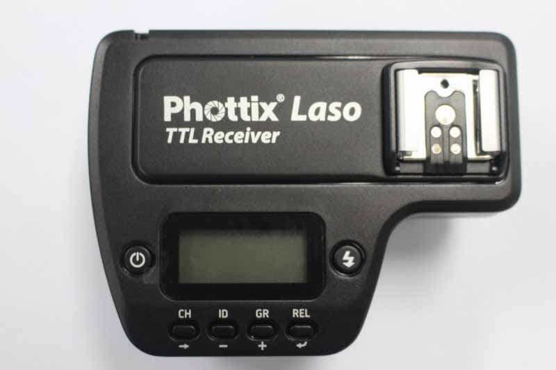
P9M-LASORX
Jun 09, 2015Phottix Laso TTL Flash Trigger Receiver
Equipment Class
DXX - Part 15 Low Power Communication Device Transmitter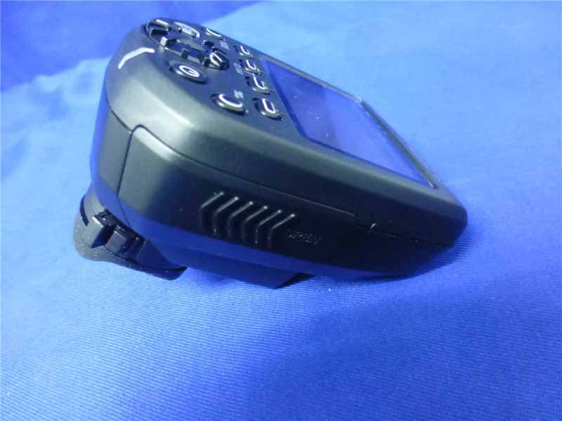
P9M-LASOTX
Jun 09, 2015Phottix Laso TTL Flash Trigger Transmitter
Equipment Class
DXX - Part 15 Low Power Communication Device Transmitter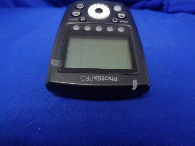
P9M-ODIN2TX
May 28, 2015Phottix PRO Odin II TTL Flash Trigger Transmitter
Equipment Class
DXX - Part 15 Low Power Communication Device Transmitter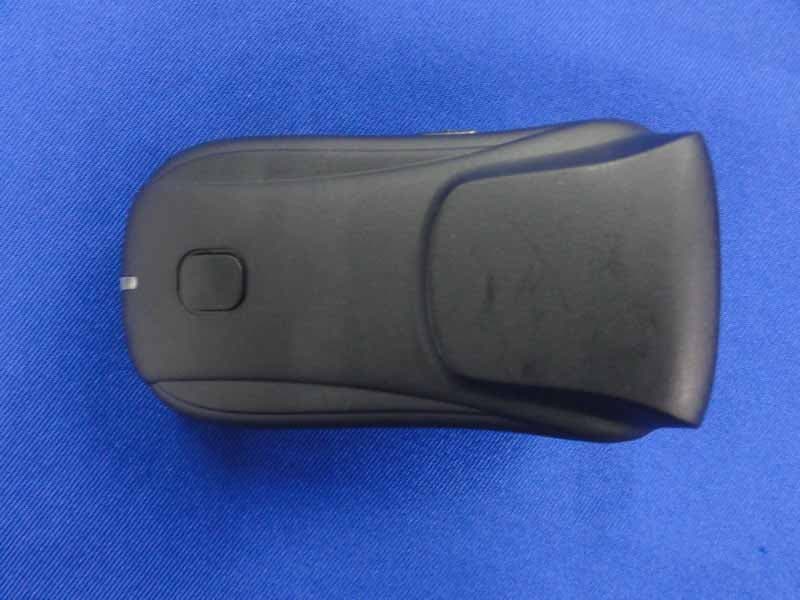
P9M-STRATOTTL
Sep 27, 2013Phottix Strato TTL Flash Trigger Transmitter
Equipment Class
DXX - Part 15 Low Power Communication Device Transmitter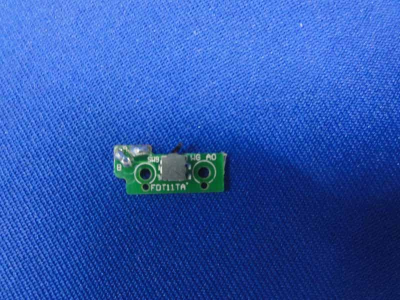
P9M-MITROSPS
Sep 12, 2013Transceiver Flash
Equipment Class
DXX - Part 15 Low Power Communication Device Transmitter