P9M-MITROSPSTransceiver Flash
Phottix (HK) Ltd.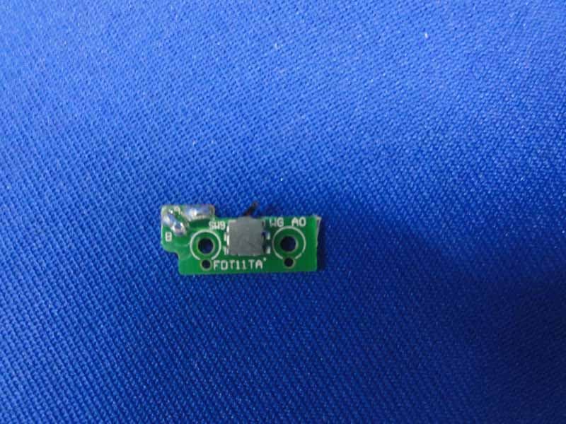
Click to zoom
Application Details
- Equipment Class
- DXX - Part 15 Low Power Communication Device Transmitter
- Date of Grant
- Sep 12, 2013
- Application Purpose
- Original Equipment
- Date of Application
- Sep 09, 2013
- Equipment Note
- Transceiver Flash
- Frequency Range
- 2464.00000000 - 2474.00000000
- Company
- Phottix (HK) Ltd.
- Country
- China
Documents & Files
Document Text
Text extracted from the exhibit documents filed with the FCC. Open a document above to read the original.
Users Manual
Phottix Mitros+ TTL Transceiver Flash for Canon Instruction Manual Note: To start immediately using this flash please refer to the quick-start guide. For advanced features please read this manual and be familiar with your camera manual and operations. The Phottix Mitros+ TTL Transceiver Flash for Canon is designed to work with Canon DSLR cameras and features ETTL I/II, Manual, Multi modes as well as Wireless Master/Slave triggering. Warnings 1. Use your flash safely. Do not fire the flash into the eyes of people or animals at short distances – damage and/or blindness can occur 2. Be careful using the flash in or around cars, buses, motorcycles or other moving vehicles as accidents can result. 3. Never use the flash near combustible gases (gasoline, solvents, etc.) 4. Do not expose the flash or batteries to dripping/splashing water, or high humidity. 5. Do not leave the flash or batteries in a hot location (direct sunlight, in a closed car, etc.) 6. Remove batteries from the flash when not being used for an extended period of time. 7. Change the batteries when required. Use undamaged batteries in good condition. Do not mix battery types or new and used batteries. 8. Do not put opaque objects in front of the flash lens when firing the flash. The energy emitted by the flash may cause objects to burn, or cause damage to the flash tube or fresnel lens. 9. Use caution in touching the flash head after use. It may be hot and can cause burns. 10. The flash contains high voltage electronic parts. Do not disassemble or attempt to repair the flash. Never touch the flash’s internal components. 11. Do not touch the External Power Port contacts with any metal objects – this can cause electric shock and serious injury. Table of Contents Parts and Functions .......................................... Modes ............................................................. Wireless Triggering.............................................. Custom Functions.............................................. Technical Specs................................................ Parts Back / Left Side 1. LCD Display 2. Mode Button 3. Test Button 4. Power Switch 5. Ready Light 6. Arrow Adjustment Buttons (see below) 7. Set Button 8. Locking Lever 9. 3.5mm Sync Port 10. USB Port 11. External Power Port Arrow Adjustment Buttons 1. Up Arrow / Zoom Adjustment Mode Button 2. Right Arrow / Wireless Flash Mode Button 3. Down Arrow / HSS / SCS Button 4. Left Button / Custom Functions Button Front / Right Side 1. Bounce Card 2. Wide Angle Diffuser 3. Flash Head 4. Wireless Signal Receiver Area 5. AF Assist Light 6. Hot Shoe 7. Battery Compartment Please note: These instruction assume: 1. Both the flash and camera are switched on. 2. The flash and camera are set to the same settings as this manual. 3. Camera menu and flash custom functions menu are set to default values. 4. The flash is being used with a compatible Canon DSLR. Installing batteries 1. Press the battery cover in while pushing it towards the bottom of the flash. The battery cover will open and raise. 2. Insert AA batteries as shown by the diagram inside the battery compartment. 3. Lower the battery cover and push back towards the top of the flash, locking it in place. Please note: - Please use four standard high-quality batteries of the same brand. Make sure all batteries are at similar powers levels. - Batteries can get hot when the flash is being used. Use caution when changing batteries. - If you do not use the flash for an extended period of time, store with batteries removed. Attaching the flash to a camera Turn off both the camera and flash 1. Align the flash hot shoe with the camera hot shoe. 2. Slide the flash into the camera hot shoe until fully inserted. 3. Lock the flash in position by pushing the locking lever to the right until the lock engages with a click. 4. To Unlock, press the locking release button on the locking lever and slide to the left. Turning the Flash On / Off 1. To power on the flash move the power switch to the on position. 2. To power off the flash move the power switch to the off position. Battery Level Indicator The Battery Level Indicator on the LCD (see below) will display an approximate indication of how much power remains in the batteries in the flash. Use this as a rough guide as to when a battery change is needed. If flash recycling time has become very long (30 seconds) change the batteries. Raising and Rotating the Flash Head 1. The flash head will elevate from -7 to 90 degrees with stops at -7, 0, 45, 60, 75 and 90 degrees. Gently raise or lower the flash head into the required position. 2. The flash head will rotate 180 degrees in either direction with stops at 60, 75, 90, 120, 150 and 180 degrees. Gently rotate the flash head into the required position. 3. When the flash head is raised or rotated from the 0 degree standard forward position the flash zoom will set itself to 50mm. “- -” will be displayed on the LCD. Flash zoom when the head is raised or rotated can be changed in MZoom mode (see below). 4. At -7 degrees the flash zoom will act the same as 0 degree – it will not change any settings. Using the Bounce Card or Wide Angle Diffuser The Phottix Mitros+ Flash comes equipped with a white bounce card and wide angle diffuser panel in the flash head. 1. The wide angle diffuser panel will cause the flash to spread light to a 14mm equivalent. 2. The white bounce card can be used when the flash head is in a raised position to bounce light forward to assist with catch lights in a subject’s eyes. To use: 1. Gently pull the diffuser panel and bounce card from the flash head using the ridge on the bottom of the diffuser panel. 2. If using the diffuser panel it will drop into position over the flash head. Gently push the bounce card back into the flash head if not needed. 3. If using the bounce card only gently push the diffuser panel back into the flash head. Using the Flash Head Diffuser The Phottix Mitros+ TTL Flash comes with an attac…
Text truncated - open the document above for the full version.
Internal Photos
R AUDIX Technology (Shenzhen) Co., Ltd. FCC ID:P9M-MITROSPS page Audix Technology (Shenzhen) Co., Ltd. Report No. ACS-F13232 9-4 Figure 7 General Appearance of the EUT Figure 8 Inside of the EUT R AUDIX Technology (Shenzhen) Co., Ltd. FCC ID:P9M-MITROSPS page Audix Technology (Shenzhen) Co., Ltd. Report No. ACS-F13232 9-5 Figure 9 Inside of the EUT Figure 10 Inside of the EUT R AUDIX Technology (Shenzhen) Co., Ltd. FCC ID:P9M-MITROSPS page Audix Technology (Shenzhen) Co., Ltd. Report No. ACS-F13232 9-6 Figure 11 Inside of the EUT Figure 12 Inside of the EUT R AUDIX Technology (Shenzhen) Co., Ltd. FCC ID:P9M-MITROSPS page Audix Technology (Shenzhen) Co., Ltd. Report No. ACS-F13232 9-7 Figure 13 Inside of the EUT Figure 14 Inside of the EUT R AUDIX Technology (Shenzhen) Co., Ltd. FCC ID:P9M-MITROSPS page Audix Technology (Shenzhen) Co., Ltd. Report No. ACS-F13232 9-8 Figure 15 Inside of the EUT Figure 16 Inside of the EUT R AUDIX Technology (Shenzhen) Co., Ltd. FCC ID:P9M-MITROSPS page Audix Technology (Shenzhen) Co., Ltd. Report No. ACS-F13232 9-9 Figure 17 Inside of the EUT Figure 18 Inside of the EUT R AUDIX Technology (Shenzhen) Co., Ltd. FCC ID:P9M-MITROSPS page Audix Technology (Shenzhen) Co., Ltd. Report No. ACS-F13232 9-10 Figure 19 Inside of the EUT Figure 20 Inside of the EUT R AUDIX Technology (Shenzhen) Co., Ltd. FCC ID:P9M-MITROSPS page Audix Technology (Shenzhen) Co., Ltd. Report No. ACS-F13232 9-11 Figure 21 Inside of the EUT Figure 22 Inside of the EUT R AUDIX Technology (Shenzhen) Co., Ltd. FCC ID:P9M-MITROSPS page Audix Technology (Shenzhen) Co., Ltd. Report No. ACS-F13232 9-12 Figure 23 Inside of the EUT Figure 24 Inside of the EUT R AUDIX Technology (Shenzhen) Co., Ltd. FCC ID:P9M-MITROSPS page Audix Technology (Shenzhen) Co., Ltd. Report No. ACS-F13232 9-13 Figure 25 Inside of the EUT Figure 26 Inside of the EUT R AUDIX Technology (Shenzhen) Co., Ltd. FCC ID:P9M-MITROSPS page Audix Technology (Shenzhen) Co., Ltd. Report No. ACS-F13232 9-14 Figure 27 Inside of the EUT
Test Report
R AUDIX Technology (Shenzhen) Co., Ltd. FCC ID:P9M-MITROSPS Audix Technology (Shenzhen) Co., Ltd. Report No. ACS-F13232 FCC PART 15C TEST REPORT FOR CERTIFICATION On Behalf of Phottix (HK) Ltd. Phottix Mitros+ TTL Transceiver Flash Model No. : Mitros+ FCC ID: P9M-MITROSPS Prepared for : Phottix (HK) Ltd. 10/F Block A, Yip Fat Factory Building, Phase l, 77 Hoi Yuen Rd, Kwun Tong, Kln, Hong Kong Prepared By : Audix Technology (Shenzhen) Co., Ltd. No. 6, Ke Feng Rd., 52 Block, Shenzhen Science & Industrial Park, Nantou, Shenzhen, Guangdong, China Tel: (0755) 26639496 Report Number : ACS-F13232 Date of Test : Aug.03~06, 2013 Date of Report : Sep.11, 2013 R AUDIX Technology (Shenzhen) Co., Ltd. FCC ID:P9M-MITROSPS Audix Technology (Shenzhen) Co., Ltd. Report No. ACS-F13232 TABLE OF CONTENTS Description Page 1. SUMMARY OF STANDARDS AND RESULTS ......................................................... 1-1 1.1. Description of Standards and Results ...................................................................................1-1 2. GENERAL INFORMATION ......................................................................................... 2-1 2.1. Description of Device (EUT) ...............................................................................................2-1 2.2. Tested Supporting System Details........................................................................................2-2 2.3. Block Diagram of Test Setup ...............................................................................................2-2 2.4. Test Facility ..........................................................................................................................2-3 2.5. Measurement Uncertainty (95% confidence levels, k=2).....................................................2-3 3. POWER LINE CONDUCTED EMISSION TEST....................................................... 3-1 4. RADIATED EMISSION TEST ...................................................................................... 4-1 4.1. Test Equipment.....................................................................................................................4-1 4.2. Block Diagram of Test Setup ...............................................................................................4-2 4.3. Radiated Emission Limit ......................................................................................................4-3 4.4. EUT Configuration on Test ..................................................................................................4-3 4.5. Operating Condition of EUT ................................................................................................4-3 4.6. Test Procedure ......................................................................................................................4-3 4.7. Radiated Emission Test Results ...........................................................................................4-4 5. BAND EDGE COMPLIANCE TEST............................................................................ 5-1 5.1. Test Equipment.....................................................................................................................5-1 5.2. Limit .....................................................................................................................................5-1 5.3. Test Produce .........................................................................................................................5-1 6. 20DB BANDWIDTH TEST ............................................................................................ 6-1 6.1. Test Equipment.....................................................................................................................6-1 6.2. Limit .....................................................................................................................................6-1 6.3. Test Results ..........................................................................................................................6-1 7. DEVIATION TO TEST SPECIFICATIONS ............................................................... 7-1 8. PHOTOGRAPH OF TEST............................................................................................. 8-1 8.1. Photos of Radiated Emission Test ........................................................................................8-1 9. PHOTOS OF THE EUT ................................................................................................. 9-1 R AUDIX Technology (Shenzhen) Co., Ltd. FCC ID:P9M-MITROSPS page Audix Technology (Shenzhen) Co., Ltd. Report No. ACS-F13232 1-1 1. SUMMARY OF STANDARDS AND RESULTS 1.1. Description of Standards and Results The EUT have been tested according to the applicable standards as referenced below. EMISSION Description of Test Item Standard Results Radiated Emission Test FCC Part 15C: 15.209 FCC Part 15C: 15.249 ANSI C63.10-2009 PASS Band Edge Compliance Test FCC Part 15: 15.249 ANSI C63.10-2009 PASS 20dB Bandwidth Test FCC Part 15: 15.215 ANSI C63.10-2009 PASS R AUDIX Technology (Shenzhen) Co., Ltd. FCC ID:P9M-MITROSPS page Audix Technology (Shenzhen) Co., Ltd. Report No. ACS-F13232 2-1 2. GENERAL INFORMATION 2.1. Description of Device (EUT) Product Name : Phottix Mitros+ TTL Transceiver Flash Model Number : Mitros+ FCC ID : P9M-MITROSPS Operation Frequency : 2464MHz-2474MHz Modulation Technology : GFSK Antenna Assembly Gain : Integrated PCB antenna, 3dBi gain Power Supply : DC 6V Applicant : Phottix (HK) Ltd. 10/F Block A, Yip Fat Factory Building, Phasel, 77 Hoi Yuen Rd, Kwun Tong, Kln, Hong Kong Manufacturer : Phottix (HK) Ltd. 10/F Block A, Yip Fat Factory Building, Phasel, 77 Hoi Yuen Rd, Kwun Tong, Kln, Hong Kong Date of Test : Aug.03~06, 2013 Date of Receipt : Aug.02, 2013 Sample Type : Prototype production R AUDIX Technology (Shenzhen) Co., Ltd. FCC ID:P9M-MITROSPS page Audix Technology (Shenzhen) Co., Ltd. Report No. ACS-F13232 2-2 2.2. T…
Text truncated - open the document above for the full version.
Test Setup Photos
R AUDIX Technology (Shenzhen) Co., Ltd. FCC ID:P9M-MITROSPS page Audix Technology (Shenzhen) Co., Ltd. Report No. ACS-F13232 8-1 8. PHOTOGRAPH OF TEST 8.1. Photos of Radiated Emission Test R AUDIX Technology (Shenzhen) Co., Ltd. FCC ID:P9M-MITROSPS page Audix Technology (Shenzhen) Co., Ltd. Report No. ACS-F13232 8-2 (Above 1000MHz)
Contact Information
Applicant
Mr. Laurence(General manager)
Test Firm
Audix Technology (Shenzhen) Co., Ltd.Smart Tsai
Technical Specifications
| # | Rule Parts | Frequency Range | Power Output |
|---|---|---|---|
| 1 | 15C | 2.46 GHz - 2.47 GHz | 7.96 mW |
Other Applications from Phottix (HK) Ltd.
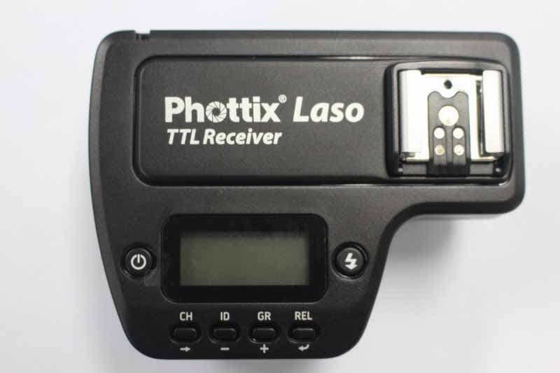
P9M-LASORX
Jun 09, 2015Phottix Laso TTL Flash Trigger Receiver
Equipment Class
DXX - Part 15 Low Power Communication Device Transmitter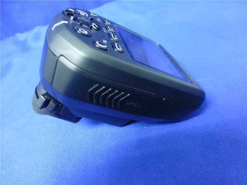
P9M-LASOTX
Jun 09, 2015Phottix Laso TTL Flash Trigger Transmitter
Equipment Class
DXX - Part 15 Low Power Communication Device Transmitter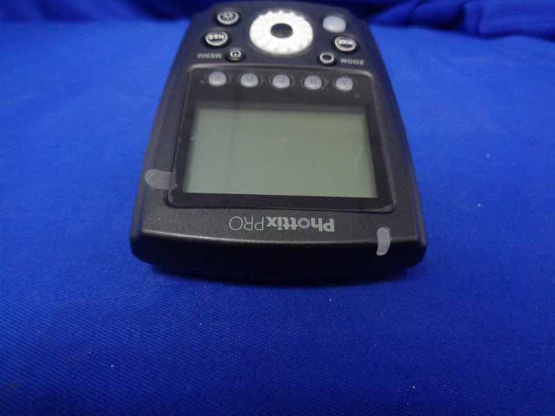
P9M-ODIN2TX
May 28, 2015Phottix PRO Odin II TTL Flash Trigger Transmitter
Equipment Class
DXX - Part 15 Low Power Communication Device Transmitter
P9M-STRATOTTL
Sep 27, 2013Phottix Strato TTL Flash Trigger Transmitter
Equipment Class
DXX - Part 15 Low Power Communication Device Transmitter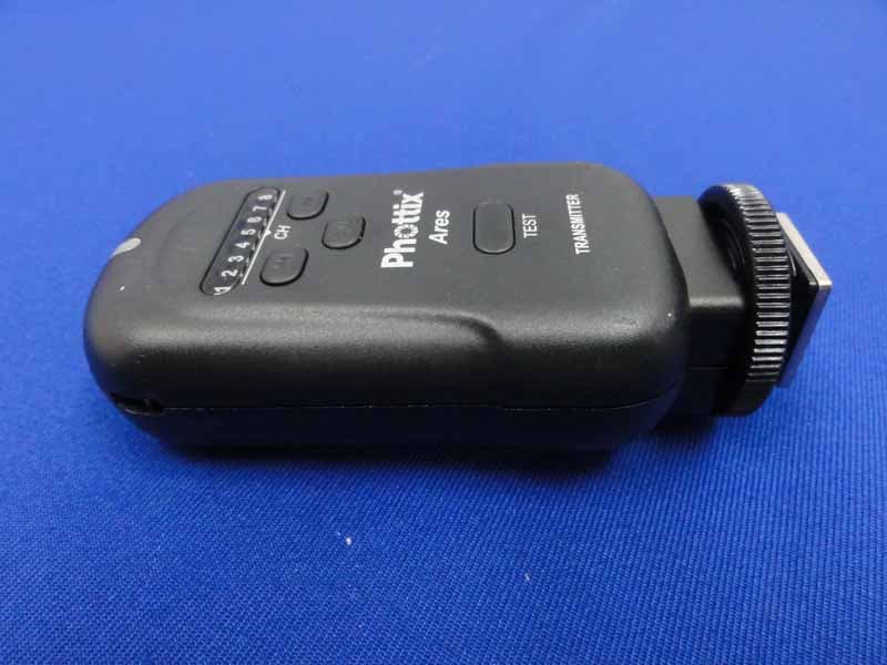
P9M-ARES
Jul 10, 2013Phottix Ares Wireless Flash Trigger
Equipment Class
DXX - Part 15 Low Power Communication Device Transmitter