P9M-LASOTXPhottix Laso TTL Flash Trigger Transmitter
Phottix (HK) Ltd.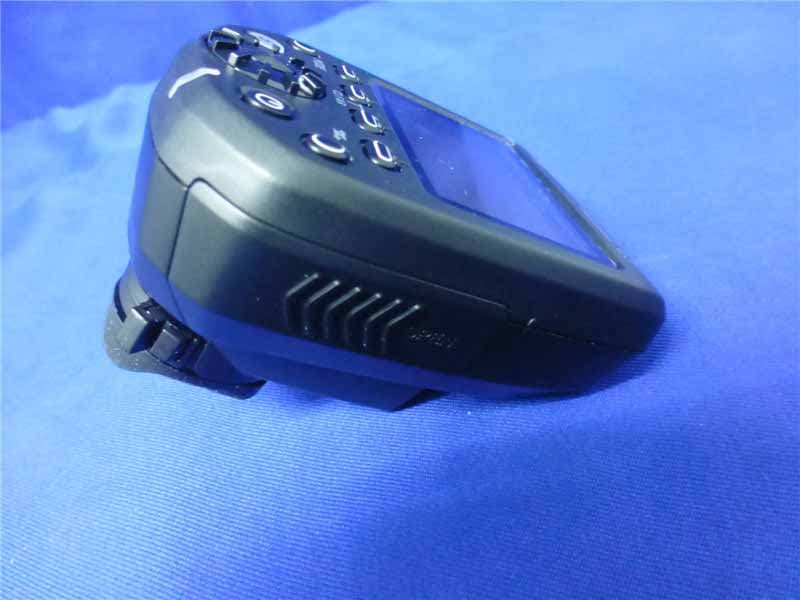
Click to zoom
Application Details
- Equipment Class
- DXX - Part 15 Low Power Communication Device Transmitter
- Date of Grant
- Jun 09, 2015
- Application Purpose
- Original Equipment
- Date of Application
- Jun 09, 2015
- Equipment Note
- Phottix Laso TTL Flash Trigger Transmitter
- Frequency Range
- 2405.00000000 - 2475.00000000
- Company
- Phottix (HK) Ltd.
- Country
- China
Documents & Files
Document Text
Text extracted from the exhibit documents filed with the FCC. Open a document above to read the original.
Users Manual
Phottix Laso TTL Flash Trigger_Transmitter Thank you for purchasing a Phottix Product Note: Before using the Phottix Laso TTL Flash Trigger, please read this instruction manual carefully, while also referring to the instruction manuals of your camera, flash and other relevant devices. Warnings 1. This product is a precise electronic instrument. Do not expose to damp environments or dust. 2. Please shut down the power of all devices when installing the wireless trigger. 3. Do not drop or crush. 4. Do not use the wireless trigger at flammable, explosive or high temperature environment. 5. Do not use harsh chemicals or solvents to clean the body. Use a soft cloth or lens paper. 6. Remove batteries from the wireless trigger if not being used for an extended period. 7. Interference: The Phottix Laso wireless trigger transmits radio signals at 2.4GHz. Its performance can be affected by electrical current, magnetic fields, radio signals, wireless routers, cellular phones, and other electronic devices. Environmental objects, such as large buildings or walls, trees, fences, or cars can also affect transmission performance. If your wireless trigger can’t be triggered, move its location slightly. FCC Interference Statement: This device complies with part 15 of the FCC Rules. Operation is subject to the followingtwo conditions: (1) This device may not cause harmful interference, and (2) this device must accept any interference received, including interference that may cause undesired operation. FCC Radiation Exposure Statement: This equipment complies with FCC RF radiation exposure limits set forth for an uncontrolled environment. This device and its antenna must not be co-located or operating in conjunction with any other antenna or transmitter. NOTE: This equipment has been tested and found to comply with the limits for a Class B digital device, pursuant to Part 15 of the FCC Rules. These limits are designed to provide reasonable protection against harmful interference in a residential installation. This equipment generates, uses and can radiate radio frequency energy and, if not installed and used in accordance with the instructions, may cause harmful interference to radio communications. However, there is no guarantee that interference will not occur in a particular installation. If this equipment does cause harmful interference to radio or television reception, which can be determined by turning the equipment off and on, the user is encouraged to try to correct the interference by one or more of the following measures: -- Reorient or relocate the receiving antenna. -- Increase the separation between the equipment and receiver. -- Connect the equipment into an outlet on a circuit different from that to which the receiver is connected. -- Consult the dealer or an experienced radio/TV technician for help. Phottix Laso Wireless Trigger for Canon/Transmitter The Phottix Laso transmitter is used for wireless flash shooting. It can control up to 5 groups (15 units) of radio-enabled Canon Speedlites, as well as non-wireless Canon ETTL Speedlites by using the Phottix Laso receiver. The transmitter supports multiple flash modes and shooting approaches including E-TTL II/E-TTL, Manual, MULTI, Ext.A and Linked Shooting. Table of Contents I. Parts II. Preparation Before Use III. The LCD Display IV. Wireless Flash Shooting: Radio Transmission 1. Wireless Flash Setting 2. ETTL: Fully Automatic Wireless Flash Shooting 3. Using Fully Automatic Wireless Flash 4. ETTL: Wireless Multiple Flash Shooting with Flash Ratio 5. M:Wireless Multiple Flash Shooting with Manual Flash Output 6. Multi: 7. Gr: Shooting with a Different Flash Mode for Each Group 8. Linked Shooting V. Setting Transmitter Functions with Camera Operations VI. Customizing the Transmitter 1.C.Fn: Setting Custom Functions 2.P.Fn: Setting Personal Functions VII. Technical Specification VII. Trouble Shooting Guide I.Parts 1.<LINK> indication light: Radio transmission confirmation lamp 2.LCD panel 3.Function Button 3 4. Function Button 2 5. Function Button 1 6.<MODE>: Flash mode button 7.< >: Charge lamp/Test flash button; 8.<>: Select/Set button 9.<>: Select dial 10.Mounting foot lock lever 11.Battery compartment cover 12.Function button 4 13. <>: Linked shooting button 14.Power button 15.Flash exposure confirmation lamp 16.Lock-release button 17.USB port 18.Remote release terminal 19.Contacts 20.Mounting foot 21.Locking pin 22.AF assist light II. Preparation before use Installing the batteries 1. Press the battery compartment cover and slide it down as shown to open the battery cover. (Picture 1) 2. Insert the batteries as shown. Make sure the “+” and“-”battery contacts are correctly oriented as shown. (Note: Please use 2 pieces of AA alkaline batteries or AA type NI-MH batteries. (Picture 2) 3. Replace the battery cover and push back into the locked position. (图一) (图二) Attaching and Removing the Phottix Laso transmitter Attaching the Phottix Laso transmitter to the camera hot shoe 1. Turn off the camera and Phottix Laso transmitter 2. Align the Phottix Laso transmitter hot shoe with camera’s hot shoe mount. 3. Slide the Phottix Laso transmitter all the way into the camera’s hot shoe mount. 4. Lock the Phottix Laso transmitter by sliding the mounting foot lock lever to the right until the lock lever clicks in place.(See picture 3) Removing the Phottix Laso Transmitter 1. Lock release: press the lock-release button while slide the lock lever all the (图三) (图四) 1 2 way back to the left.(see picture 4) 2. Slide the Phottix Laso transmitter out of camera’s hot shoe mount. Turn On/Off the Phottix Laso transmitter 1. Turn On: Press and hold the power button until MENU interface is displayed on screen. 2. Turn off: Press and hold the power button until the LCD screen goes blank. Note: When is displayed, please replace the batteries with new ones. Checking the version info of the Phottix Laso transmitter You can check the present version information on Phottix…
Text truncated - open the document above for the full version.
External Photos
R AUDIX Technology (Shenzhen) Co., Ltd. FCC ID:P9M-LASOTX page Audix Technology (Shenzhen) Co., Ltd. Report No. ACS-F15157 11-1 11. PHOTOGRAPH OF EUT Figure 1 General Appearance of the EUT Figure 2 General Appearance of the EUT R AUDIX Technology (Shenzhen) Co., Ltd. FCC ID:P9M-LASOTX page Audix Technology (Shenzhen) Co., Ltd. Report No. ACS-F15157 11-2 Figure 3 General Appearance of the EUT Figure 4 General Appearance of the EUT R AUDIX Technology (Shenzhen) Co., Ltd. FCC ID:P9M-LASOTX page Audix Technology (Shenzhen) Co., Ltd. Report No. ACS-F15157 11-3 Figure 5 General Appearance of the EUT Figure 6 General Appearance of the EUT R AUDIX Technology (Shenzhen) Co., Ltd. FCC ID:P9M-LASOTX page Audix Technology (Shenzhen) Co., Ltd. Report No. ACS-F15157 11-4 Figure 7 General Appearance of the EUT Figure 8 Inside of the EUT
ID Label/Location Info
对外产品名称和型号LIST 对外产品名称对外产品型号FCCID 号码 发射器 Phottix Laso TTL Flash Trigger Transmitter Laso (T) P9M-LASOTX 接收器 Phottix Laso TTL Flash Trigger Receiver Laso (R) P9M-LASORX 商标仕样: FCCID 标签的仕样: FCCID 标签的位置仕样:
Internal Photos
R AUDIX Technology (Shenzhen) Co., Ltd. FCC ID:P9M-LASOTX page Audix Technology (Shenzhen) Co., Ltd. Report No. ACS-F15157 11-5 Figure 9 Inside of the EUT Figure 10 Inside of the EUT R AUDIX Technology (Shenzhen) Co., Ltd. FCC ID:P9M-LASOTX page Audix Technology (Shenzhen) Co., Ltd. Report No. ACS-F15157 11-6 Figure 11 Inside of the EUT Figure 12 Inside of the EUT R AUDIX Technology (Shenzhen) Co., Ltd. FCC ID:P9M-LASOTX page Audix Technology (Shenzhen) Co., Ltd. Report No. ACS-F15157 11-7 Figure 13 Inside of the EUT Figure 14 Inside of the EUT R AUDIX Technology (Shenzhen) Co., Ltd. FCC ID:P9M-LASOTX page Audix Technology (Shenzhen) Co., Ltd. Report No. ACS-F15157 11-8 Figure 15 Inside of the EUT Figure 16 Inside of the EUT R AUDIX Technology (Shenzhen) Co., Ltd. FCC ID:P9M-LASOTX page Audix Technology (Shenzhen) Co., Ltd. Report No. ACS-F15157 11-9 Figure 17 Inside of the EUT Figure 18 Component Side of the PCB R AUDIX Technology (Shenzhen) Co., Ltd. FCC ID:P9M-LASOTX page Audix Technology (Shenzhen) Co., Ltd. Report No. ACS-F15157 11-10 Figure 19 Component Side of the PCB Figure 20 Component Side of the PCB R AUDIX Technology (Shenzhen) Co., Ltd. FCC ID:P9M-LASOTX page Audix Technology (Shenzhen) Co., Ltd. Report No. ACS-F15157 11-11 Figure 21 Component Side of the PCB Figure 22 Component Side of the PCB R AUDIX Technology (Shenzhen) Co., Ltd. FCC ID:P9M-LASOTX page Audix Technology (Shenzhen) Co., Ltd. Report No. ACS-F15157 11-12 Figure 23 VIDEO OUT Cable
RF Exposure Info
R AUDIX Technology (Shenzhen) Co., Ltd. FCC ID:P9M-LASOTX page Audix Technology (Shenzhen) Co., Ltd. Report No. ACS-F15157 8-1 8. RADIO FRREQUENCY EXPOSURE COMPLIANCE RESULT : PASS Test standard : FCC KDB Publication 447498 D01 V05 Since maximum peak output power of the transmitter is<10mW, i.e.0.009346mW<10mW, hence the EUT is excluded from SAR evaluation according to FCC KDB Publication 447498 D01:General RF Exposure Guidance V05.
Test Report
R AUDIX Technology (Shenzhen) Co., Ltd. FCC ID:P9M-LASOTX Audix Technology (Shenzhen) Co., Ltd. Report No. ACS-F15157 FCC PART 15C TEST REPORT FOR CERTIFICATION On Behalf of Phottix (HK) Ltd. Phottix Laso TTL Flash Trigger Transmitter Model Number: Laso (T) FCC ID: P9M-LASOTX Prepared for : Phottix (HK) Ltd. 10/F Block A, Yip Fat Factory Building, Phase 1, 77 Hoi Yuen Rd, Kwun Tong, Kln, Hong Kong Prepared By : Audix Technology (Shenzhen) Co., Ltd. No. 6, Ke Feng Rd., 52 Block, Shenzhen Science & Industrial Park, Nantou, Shenzhen, Guangdong, China Tel: (0755) 26639496 Report Number : ACS-F15157 Date of Test : Feb.13~17, 2015 Date of Report : Jun.04, 2015 R AUDIX Technology (Shenzhen) Co., Ltd. FCC ID:P9M-LASOTX Audix Technology (Shenzhen) Co., Ltd. Report No. ACS-F15157 TABLE OF CONTENTS Description Page 1. SUMMARY OF STANDARDS AND RESULTS.......................................................... 1-1 1.1. Description of Standards and Results .................................................................................. 1-1 2. GENERAL INFORMATION ......................................................................................... 2-1 2.1. Description of Device (EUT) ............................................................................................... 2-1 2.2. Tested Supporting System Details ....................................................................................... 2-1 2.3. EUT Configuration and operation conditions for test.......................................................... 2-1 2.4. Test Facility ......................................................................................................................... 2-2 2.5. Measurement Uncertainty (95% confidence levels, k=2) .................................................... 2-2 3. POWER LINE CONDUCTED EMISSION TEST ....................................................... 3-1 4. RADIATED EMISSION TEST ...................................................................................... 4-1 4.1. Test Equipment .................................................................................................................... 4-1 4.2. Block Diagram of Test Setup ............................................................................................... 4-2 4.3. Radiated Emission Limit Standard: FCC 15.209 and 15.249 .............................................. 4-3 4.4. EUT Configuration on Test.................................................................................................. 4-3 4.5. Operating Condition of EUT................................................................................................ 4-3 4.6. Test Procedure...................................................................................................................... 4-3 4.7. Radiated Emission Test Results ........................................................................................... 4-4 5. 20 DB BANDWIDTH TEST ........................................................................................... 5-1 5.1. Test Equipment .................................................................................................................... 5-1 5.2. Limit..................................................................................................................................... 5-1 5.3. Test Results .......................................................................................................................... 5-1 6. BAND EDGE COMPLIANCE TEST ............................................................................ 6-1 6.1. Test Equipment .................................................................................................................... 6-1 6.2. Limit..................................................................................................................................... 6-1 6.3. Test Produce ......................................................................................................................... 6-1 6.4. Test Results .......................................................................................................................... 6-1 7. ANTENNA REQUIREMENT ........................................................................................ 7-1 8. RADIO FRREQUENCY EXPOSURE COMPLIANCE.............................................. 8-1 9. DEVIATION TO TEST SPECIFICATIONS................................................................ 9-1 10. PHOTOGRAPH OF TEST ........................................................................................... 10-1 10.1. Photos of Radiated Emission Test...................................................................................... 10-1 11. PHOTOGRAPH OF EUT ............................................................................................. 11-1 R AUDIX Technology (Shenzhen) Co., Ltd. FCC ID:P9M-LASOTX page Audix Technology (Shenzhen) Co., Ltd. Report No. ACS-F15157 1-1 1. SUMMARY OF STANDARDS AND RESULTS 1.1. Description of Standards and Results The EUT have been tested according to the applicable standards as referenced below. EMISSION Description of Test Item Standard Results Power Line Conducted Emission Test FCC Part 15C: 15.207 ANSI C63.10-2009 N/A Radiated Emission Test FCC Part 15C: 15.209 FCC Part 15C: 15.249 ANSI C63.10-2009 PASS Band Edge Compliance Test FCC Part 15: 15.249 ANSI C63.10-2009 PASS 20dB Bandwidth Test FCC Part 15: 15.215 ANSI C63.10-2009 PASS N/A is an abbreviation for Not Applicable. R AUDIX Technology (Shenzhen) Co., Ltd. FCC ID:P9M-LASOTX page Audix Technology (Shenzhen) Co., Ltd. Report No. ACS-F15157 2-1 2. GENERAL INFORMATION 2.1. Description of Device (EUT) Product Name : Phottix Laso TTL Flash Trigger Transmitter Model Number : Laso (T) FCC ID : P9M-LASOTX Operation frequency : 2405MHz-2475MHz Antenna : Internal PCB PIFA Antenna, 3.0dBi gain Applicant : Phottix (HK) Ltd. 10/F Block A, Yip Fat Factory Building, Phase 1, 77 Hoi …
Text truncated - open the document above for the full version.
Test Setup Photos
R AUDIX Technology (Shenzhen) Co., Ltd. FCC ID:P9M-LASOTX page Audix Technology (Shenzhen) Co., Ltd. Report No. ACS-F15157 10-1 10. PHOTOGRAPH OF TEST 10.1. Photos of Radiated Emission Test (At Anechoic 3m Chamber Test 30-1000MHz) R AUDIX Technology (Shenzhen) Co., Ltd. FCC ID:P9M-LASOTX page Audix Technology (Shenzhen) Co., Ltd. Report No. ACS-F15157 10-2 (At Anechoic 3m Chamber Test 1GHz –18GHz)
Contact Information
Applicant
Mr. Laurence(General manager)
Test Firm
Audix Technology (Shenzhen) Co., Ltd.Smart Tsai
Technical Specifications
| # | Rule Parts | Frequency Range | Power Output |
|---|---|---|---|
| 1 | 15C | 2.40 GHz - 2.48 GHz | - |
Other Applications from Phottix (HK) Ltd.
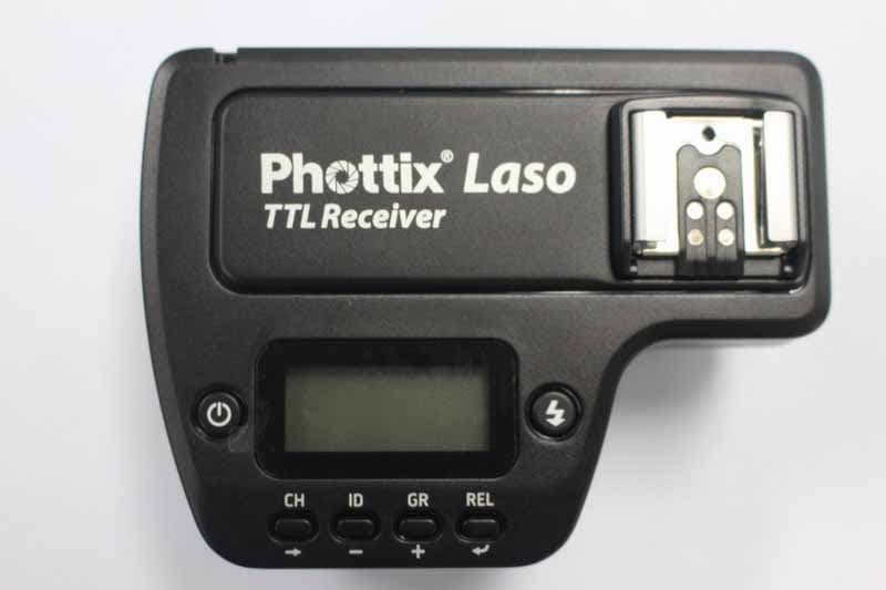
P9M-LASORX
Jun 09, 2015Phottix Laso TTL Flash Trigger Receiver
Equipment Class
DXX - Part 15 Low Power Communication Device Transmitter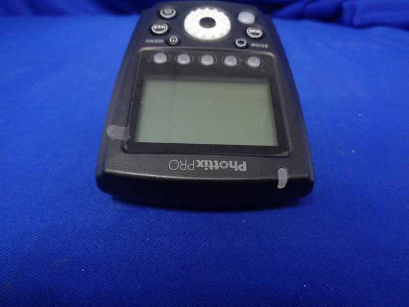
P9M-ODIN2TX
May 28, 2015Phottix PRO Odin II TTL Flash Trigger Transmitter
Equipment Class
DXX - Part 15 Low Power Communication Device Transmitter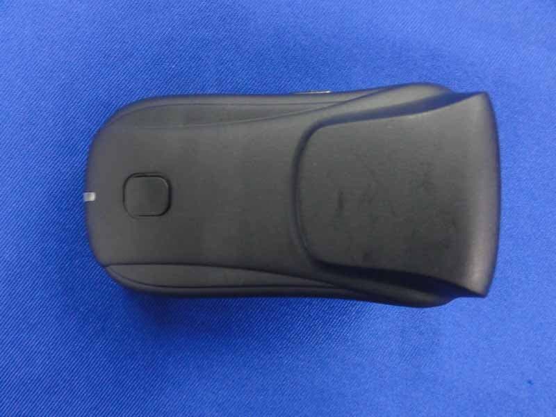
P9M-STRATOTTL
Sep 27, 2013Phottix Strato TTL Flash Trigger Transmitter
Equipment Class
DXX - Part 15 Low Power Communication Device Transmitter
P9M-MITROSPS
Sep 12, 2013Transceiver Flash
Equipment Class
DXX - Part 15 Low Power Communication Device Transmitter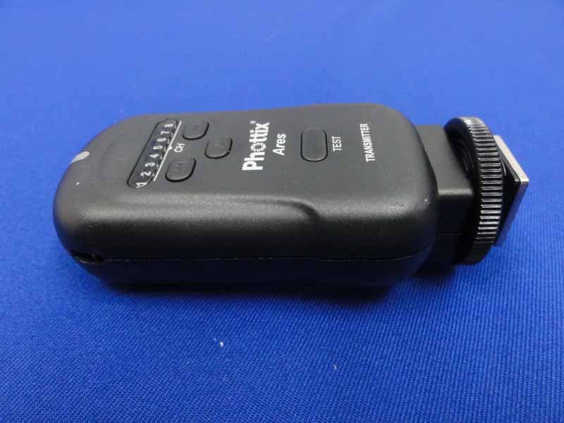
P9M-ARES
Jul 10, 2013Phottix Ares Wireless Flash Trigger
Equipment Class
DXX - Part 15 Low Power Communication Device Transmitter