PBKMS010039MIFARE Contactless Card & Fingerprint Reader
Precise Biometrics AB
Click to zoom
Application Details
- Equipment Class
- DXT - Part 15 Low Power Transceiver, Rx Verified
- Date of Grant
- Mar 05, 2002
- Application Purpose
- Original Equipment
- Date of Application
- Mar 05, 2002
- Equipment Note
- MIFARE Contactless Card & Fingerprint Reader
- Frequency Range
- 13.56000000 - 13.56000000
- Company
- Precise Biometrics AB
- Country
- Sweden
Documents & Files
Document Text
Text extracted from the exhibit documents filed with the FCC. Open a document above to read the original.
Users Manual
Document No FAXE/LET/0066/PB Date 2002-03-06 Revision A Page 1/1 Precise Biometrics AB Address: Phone: Fax: E-mail: WWW: Dag Hammarskjölds väg 2 +46(46)311100 +46(46)311101 [email protected] www.precisebiometrics.com SE-224 64 Lund, Sweden Additional Statements for the Precise BioAccess Mifare The following additional text will be include in the instructions delivered with the product: This device has been certified to the FCC rules and regulations (CFR47 Part 15 Subpart C) for the low power transmitter contained within this device. In addition, this device has also been verified to comply with Class B digital device requirements as specified in the FCC rules and regulations (CFR47 Part 15 Subpart B). NOTE: This equipment has been tested and found to comply with the limits for a Class B digital device, pursuant to Part 15 of the FCC Rules. These limits are designed to provide reasonable protection against harmful interference in a residential installation. This equipment generates, uses and can radiate radio frequency energy and, if not installed and used in accordance with the instructions, may cause harmful interference to radio communications. However, there is no guarantee that interference will not occur in a particular installation. If this equipment does cause harmful interference to radio or television reception, which can be determined by turning the equipment off and on, the user is encouraged to try to correct the interference by one or more of the following measures: - Reorient or relocate the receiving antenna. - Increase the separation between the equipment and receiver. - Connect the equipment into an outlet on a circuit different from that to which the receiver is connected. - Consult the dealer or an experienced radio/TV technician for help. CAUTION: Changes or modifications not expressly approved by the party responsible for Compliance could void the user’s authority to operate the equipment
Users Manual
Installation of Precise BioAccess ̧ 2. 1. Fasten the holder onto the wall. Mount Precise BioAccess ̧ onto the holder. Torque max 1.0 Nm. Plug the connector. 4. 3. 1 Do not connect 2 DATA (magstripe) / DATA 0 (Wiegand) OUTPUT 3 CLOCK (magstripe) / DATA 1 (Wiegand) OUTPUT 4 CARD PRESENT OUTPUT 5 Tamper switch loop6 Tamper switch loop7 GROUND (power)8* Upper red LED (5V = on) INPUT 9* Upper green LED (5V = on) INPUT 10 POWER 12-24 VDC 5. Secu re Precise BioAcces s ̧ . Use only screw driver Torx T 10 . *See Operation mode on opposite page access control side of the system. Recomended mounting height 1,4meter/4.6 feet. Connect the wi res using a shielded cable. The shielding must be connected to earth at the Operation mode 2. Unscrew the four screws on the back ofPrecise BioAccess ̧ . 1 . Loosen the to p. 2 . P ress back cover slightly upwa rd s . 3 . Pull apart . AM0100 18 R1B Mar. -02 Installation of Precise BioAccess ̧ Dag Hammarskjöldsväg 2, SE-224 64 Lund, Sweden. Phone +46 46 311 100, Fax +46 46 311 101 [email protected] www.precisebiometrics.com 1.3. , Function ON OFF 1. Sound Inactive * Active 2. Upper LED control Active * Inactive 3. Customized card No. Enabled * Disable 4. RFU Forbidden! * Must be OFF *) Factory settings CE Notice (Europe)This device meets the following technical standards as indicated by the symbolon the device: • EN 55022:1998 Limit B (Radiated emission)• EN 55024:1998 (Immunity of IT-equipment)• EN 61000-6-2:1999 (Immunity for industrial environments)• EN 300 330-2: v.1.1.1 (06-2001) (Radio - spectrum)• EN 301 489-01: v.1.2.1 (07-2000) (Radio - EMC)• EN 301 489-03 (07-2000) (Radio - EMC) FCC Information (U.S.A.)This device has been certified to the FCC rules and regulations (CFR47 Part 15 Subpart C) forthe low power transmitter contained within this device. In addition, this device has also beenverified to comply with Class B digital device requirements as specified in the FCCrules andregulations (CFR47 Part 15 Subpart B).This device complies with Part 15 of the FCC Rules. Operation is subject to the following twoconditions: (1) this device may not cause harmful interference, and (2) this device must acceptany interference received, including interference that may cause undesired operation.NOTE: This equipment has been tested and found to comply with the limits for a Class B digi-tal device, pursuant to Part 15 of the FCC Rules. These limits are designed to provide reason-able protection against harmful interference in a residential installation. This equipment gener-ates, uses and can radiate radio frequency energy and, if not installed and used in accordancewith the instructions, may cause harmful interference to radio communications. However, thereis no guarantee that interference will not occur in a particular installation. If this equipmentdoes cause harmful interference to radio or television reception, which can be determined byturning the equipment off and on, the user is encouraged to try to correct the interference byone or more of the following measures: • Reorient or relocate the receiving antenna.• Increase the separation between the equipment and receiver is connected • Connect the equipment into an outlet on a circuit different from that to which the receiver • Consult the dealer or an experienced radio/TVtechnician for help CAUTION: Changes or modifications not expressly approved by the party responsible forcompliance could void the user`s authority to operate the equipment.
Cover Letter(s)
Document No FAXE/LET/0041/PB Author Håkan Lohmander Date 2002-02-01 Revision A Page 1/1 Precise Biometrics AB Address: Phone: Fax: E-mail: WWW: Dag Hammarskjölds väg 2 +46(46)311100 +46(46)311101 [email protected] www.precisebiometrics.com SE-224 64 Lund, Sweden Request for Confidentiality Friday, 01 February 2002 American Telecommunications Certification Body, Inc. 6731 Whittier Avenue Suite C110 McLean, VA 22101 RE: Certification Application FCC ID: PBKMS010039 Please be advised that the following information is to be held confidential and behalf of Precise Biometrics AB: • Schematics • Block Diagram • Bill of Materials (Parts List) • Circuit description and statement of how the device operates • Modification Letter The application contains technical information, which Precise Biometrics AB deems to be trade secrets and proprietary. If made public, the information might be used to the disadvantage of the applicant in the market place. Thank you for your attention to this matter. Håkan Lohmander
Cover Letter(s)
2002-03-06 vs/vs A0135/2002 DELTA Danish Electronics, Light & Acoustics Venlighedsvej 4 2970 Hørsholm Denmark Tel. (+45) 72 19 40 00 Fax (+45) 72 19 40 01 www.delta.dk VAT DK 12275110 To Reviewing Engineer Ref.:FCC ID PBKMS010039 Replies to Comments covering last 5 points of letter "ATCB Comment_021302.pdf" Based on the comments received from ATCB the following new tests have been conducted: • Radiated emission below 30 MHz using a magnetic loop antenna • Conducted emission tests following the procedures of ANSI C63.4 The results of the measurements have been incorporated in the DELTA test report DANAK 196060, Project no. K222371-7 titled "Emission tests to FCC requirements of Precise Bio- Access(tm) Mifare DC/W Reader". This report is part of the exhibits for FCC ID PBKMS010039. The updated report is based on the following: CommentThe test results given in Annex 4 show both a level and transducer. Please confirm that the transducer value is already calculated/corrected for in the Level shown in the 2nd column. ReplyWe confirm that the transducer value is already calculated/corrected for in the Level shown in the 2nd column. CommentThe conducted emissions setup is not consistent with the procedure specified by ANSI C63.4 (i.e. location of LISN, presence of vertical ground plane, etc.). ReplyThe conducted measurements have been re-tested to be in compliance with the ANSI C63.4 requirements. The test results are incorporated in the refer- enced report. CommentThe 9 meter and 30 meter tests show the unit positioned on its side, while typically the unit would be installed in an upright position. Please explain. ReplyThe unit was turned and twisted until maximum field strength was meas- ured. Final measurements were performed with the EUT in this worst-case position. 2 of 2 In the updated report, however, where final measurements at the 30 m dis- tance is performed using a loop antenna, the maximum level is reached when the unit is in an upright position CommentANSI C63.4 (as referenced by 15.31) specifies frequency stability to be per- formed in 10 degree increments. Data was not provided for -10, 0, 10, 30, and 40 degree C. Please provide either the missing test data or provide a notation on the data page with a de- scription of the engineering judgement used for not supplying this data. ReplyThe EUT is normally operated continuously and can therefore be energised while inside the test chamber. During the tests the EUT was left on during temperature changes and switched off when extreme high and low tempera- tures were reached. Left off for 10 min and then switched on. Frequency measurements were performed at switch on and again two, five and ten minutes after that. An attached spectrum analyzer configured in max-hold mode is monitoring the carrier output during the temperature transition periods. In this way it can be seen if the frequency during temperature transitions makes any changes or jumps that exceeds the frequency at the extreme temperatures. To increase accuracy a marker from an external RF generator is introduced. In this way it can be confirmed that the unit is within specifications in the complete temperature span - 20 degC to + 50 degC. CommentFor tests below 30 MHz, the FCC only allows use of the magnetic loop an- tenna. The list of test instruments includes both a rod antenna and loop an- tenna. Please confirm that the loop antenna was used for all measurements below 30 MHz. Please explain the use of the rod antenna. ReplyThe radiated emission from the EUT at frequencies below 30 MHz have been re-tested using a magnetic loop antenna. The results are incorporated in the referenced DELTA report. Respectfully submitted DELTA Vagn Sylvest
Cover Letter(s)
American Telecommunications Certification Body Inc. 6731 Whittier Ave, McLean, VA 22101 February 14, 2002 RE: Precise Biometrics AB FCC ID: PBKMS010039 After a review of the submitted information, I have a few comments on the above referenced Application. 1) Previous units for Precise Biometrics AB have been considered PC Peripheral devices. The product literature for this device shows that the unit may contain an RS232 or RS485 output (requiring certification or DoC authorization, or possibly verification depending on intended use), while the test report appears to show that the unit was tested only with a Wiegand output (requiring only verification authorization). Where the additional optional outputs tested? If the unit may contain an RS232 output, then may the EUT be considered to be a composite device subject to both the requirements of a PC Peripheral & Mifare TX requirements? 2) Please provide clearer or higher resolution internal photographs. 3) The label appears to have plenty of space available and therefore should also include the statements specified by 15.19(a)(3). 4) The test results given in Annex 4 show both a level and transducer. Please confirm that the transducer value is already calculated/corrected for in the Level shown in the 2 nd column. 5) The conducted emissions setup is not consistent with the procedure specified by ANSI C63.4 (i.e. location of LISN, presence of vertical ground plane, etc.). 6) The 9 meter and 30 meter tests show the unit positioned on its side, while typically the unit would be installed in an upright position. Please explain. 7) ANSI C63.4 (as referenced by 15.31) specifies frequency stability to be performed in 10 degree increments. Data was not provided for -10, 0, 10, 30, and 40 degree C. Please provide either the missing test data or provide a notation on the data page with a description of the engineering judgment used for not supplying this data. 8) For tests below 30 MHz, the FCC only allows use of the magnetic loop antenna. The list of test instruments includes both a rod antenna and loop antenna. Please confirm that the loop antenna was used for all measurements below 30 MHz. Please explain the use of the rod antenna. Timothy R. Johnson Examining Engineer mailto: [email protected] The items indicated above must be submitted before processing can continue on the above referenced application. Failure to provide the requested information may result in application termination. Correspondence should be considered part of the permanent submission and may be viewed from the Internet after a Grant of Equipment Authorization is issued. Please do not respond to this correspondence using the email reply button. In order for your response to be processed expeditiously, you must submit your documents through the AmericanTCB.com website. Also, please note that partial responses increase processing time and should not be submitted. Any questions about the content of this correspondence should be directed to the sender.
Cover Letter(s)
2002-03-06 vs/vs A0135/2002 DELTA Danish Electronics, Light & Acoustics Venlighedsvej 4 2970 Hørsholm Denmark Tel. (+45) 72 19 40 00 Fax (+45) 72 19 40 01 www.delta.dk VAT DK 12275110 To Reviewing Engineer Ref.:FCC ID PBKMS010039 Replies to Comments covering last 5 points of letter "ATCB Comment_021302.pdf" Based on the comments received from ATCB the following new tests have been conducted: • Radiated emission below 30 MHz using a magnetic loop antenna • Conducted emission tests following the procedures of ANSI C63.4 The results of the measurements have been incorporated in the DELTA test report DANAK 196060, Project no. K222371-7 titled "Emission tests to FCC requirements of Precise Bio- Access(tm) Mifare DC/W Reader". This report is part of the exhibits for FCC ID PBKMS010039. The updated report is based on the following: CommentThe test results given in Annex 4 show both a level and transducer. Please confirm that the transducer value is already calculated/corrected for in the Level shown in the 2nd column. ReplyWe confirm that the transducer value is already calculated/corrected for in the Level shown in the 2nd column. CommentThe conducted emissions setup is not consistent with the procedure specified by ANSI C63.4 (i.e. location of LISN, presence of vertical ground plane, etc.). ReplyThe conducted measurements have been re-tested to be in compliance with the ANSI C63.4 requirements. The test results are incorporated in the refer- enced report. CommentThe 9 meter and 30 meter tests show the unit positioned on its side, while typically the unit would be installed in an upright position. Please explain. ReplyThe unit was turned and twisted until maximum field strength was meas- ured. Final measurements were performed with the EUT in this worst-case position. 2 of 2 In the updated report, however, where final measurements at the 30 m dis- tance is performed using a loop antenna, the maximum level is reached when the unit is in an upright position CommentANSI C63.4 (as referenced by 15.31) specifies frequency stability to be per- formed in 10 degree increments. Data was not provided for -10, 0, 10, 30, and 40 degree C. Please provide either the missing test data or provide a notation on the data page with a de- scription of the engineering judgement used for not supplying this data. ReplyThe EUT is normally operated continuously and can therefore be energised while inside the test chamber. During the tests the EUT was left on during temperature changes and switched off when extreme high and low tempera- tures were reached. Left off for 10 min and then switched on. Frequency measurements were performed at switch on and again two, five and ten minutes after that. An attached spectrum analyzer configured in max-hold mode is monitoring the carrier output during the temperature transition periods. In this way it can be seen if the frequency during temperature transitions makes any changes or jumps that exceeds the frequency at the extreme temperatures. To increase accuracy a marker from an external RF generator is introduced. In this way it can be confirmed that the unit is within specifications in the complete temperature span - 20 degC to + 50 degC. CommentFor tests below 30 MHz, the FCC only allows use of the magnetic loop an- tenna. The list of test instruments includes both a rod antenna and loop an- tenna. Please confirm that the loop antenna was used for all measurements below 30 MHz. Please explain the use of the rod antenna. ReplyThe radiated emission from the EUT at frequencies below 30 MHz have been re-tested using a magnetic loop antenna. The results are incorporated in the referenced DELTA report. Respectfully submitted DELTA Vagn Sylvest
External Photos
Document No FAXE/LET/0031/PB Date 2001-12-19 Revision A Page 1/3 Precise Biometrics AB Address: Phone: Fax: E-mail: WWW: Dag Hammarskjölds väg 2 +46(46)311100 +46(46)311101 [email protected] www.precisebiometrics.com SE-224 64 Lund, Sweden External photographs of Precise BioAccess Mifare Document No: FAXE/LET/0031/PB Date: 2001-12-19 Revision: A Page: 2/3 The Precise BioAccess Mifare reader The Precise BioAccess Mifare reader Document No: FAXE/LET/0031/PB Date: 2001-12-19 Revision: A Page: 3/3 The Precise BioAccess Mifare reader The Precise BioAccess Mifare reader
ID Label/Location Info
Document No FAXE/LET/0036/PB Date 2002-02-07 Revision A Page 1/2 Precise Biometrics AB Address: Phone: Fax: E-mail: WWW: Dag Hammarskjölds väg 2 +46(46)311100 +46(46)311101 [email protected] www.precisebiometrics.com SE-224 64 Lund, Sweden FCC ID Label Location and Information for Precise BioAccess Mifare Reader Document No: FAXE/LET/0036/PB Date: 2002-02-07 Revision: A Page: 2/2 Label size: Ca 53 mm x ca 34 mm. Label type: Self-adhesive label. FCC text: PBKMS010039. FCC font: 8 point Arial. Below: Drawing of label to be placed on backside of reader. FCC ID: PBKMS010039 Ca 34 mm Ca 53 mm FCC ID: PBKMS010039 Ca 34 mm Ca 53 mm Location of label
ID Label/Location Info
Document No FAXE/LET/0062/PB Author Håkan Lohmander Date 2002-02-28 Revision B Page 1/1 Precise Biometrics AB Address: Phone: Fax: E-mail: WWW: Dag Hammarskjölds väg 2 +46(46)311100 +46(46)311101 [email protected] www.precisebiometrics.com SE-224 64 Lund, Sweden To: Reviewing Engineer Ref: FCC ID: PBKMS010039 Reply to comment regarding labelling in letter "ATCB Comment_021302.pdf" Comment The label appears to have plenty of space available and therefore should also include the statements specified by 15.19(a)(3). Reply: Additional information has to be printed on the label as well. For example the label will include Product No., Production Week, Serial No., Serial No. barcode, CE-logo etc. When this information has been printed on the label there is no space left for the statement specified by 15.19(a)(3). However, the information of 15.19(a)(3) will be placed in the users manual as stipulated by 15.19(a)(5). The design of the device does not permit additional labels. Håkan Lohmander Project Manager
Internal Photos
Document No FAXE/LET/0033/PB Date 2002-02-20 Revision B Page 1/6 Precise Biometrics AB Address: Phone: Fax: E-mail: WWW: Dag Hammarskjölds väg 2 +46(46)311100 +46(46)311101 [email protected] www.precisebiometrics.com SE-224 64 Lund, Sweden Internal Photographs of Precise BioAccess Mifare Document No: FAXE/LET/0033/PB Date: 2002-02-20 Revision: B Page: 2/6 The different parts of the Precise BioAccess Mifare reader Number: Item 1 Front cover 2 Fingerprint sensor 3 I/O PCA 4 Antenna PCA 5 CPU PCA 6 Back cover Precise BioAccess Mifare front cover with fingerprint sensor 3 4 2 5 6 1 Document No: FAXE/LET/0033/PB Date: 2002-02-20 Revision: B Page: 3/6 Precise BioAccess Mifare front cover with I/O PCA and fingerprint sensor Precise BioAccess Mifare front cover Precise BioAccess Mifare back cover Document No: FAXE/LET/0033/PB Date: 2002-02-20 Revision: B Page: 4/6 Front I/O PCA Back I/O PCA Document No: FAXE/LET/0033/PB Date: 2002-02-20 Revision: B Page: 5/6 Front Antenna PCA Back Antenna PCA Document No: FAXE/LET/0033/PB Date: 2002-02-20 Revision: B Page: 6/6 Front CPU PCA Back CPU PCA
Operational Description
ENTER •IDENTIFIES PEOPLE, NOT PIN CODES •RELIABLE ONE-TO-ONE MATCHING •PLUG AND PLAY •COMPATIBLE WITH ALL MAJOR ACCESS-CONTROL SYSTEMS PRECISE BIOACCESS ™ Product Information Precise BioAccess™ is a plug and play fingerprint reader that offers unparalleled security for access control. Our unique Precise BioMatch™ technology provides reliable one-to-one matches – personal proof that people are who they claim to be. Precise BioAccess™ is compatible with Data/Clock (Magstripe), Wiegand 26-56 bits and RS485. Match-on-card technology is also supported. Precise BioAccess™ uses templates stored in a handy database and comes in three models. Precise BioAccess™ is convenient, fast, accurate, easy to implement and extremely cost effective. It’s ideal for new systems and a straightforward, inexpensive way to heighten security in existing systems. PREB-9058 01-10-25 15.38 Sida 1 Contact Smart Card FEATURES • Sound On/Off • External LED control • Encrypted template storage • Easy installation • No new wiring • No new software upgrades for access control system • Ready for MOC • Matching technique: Precise BioMatch™ TECHNICAL SPECIFICATIONS • Size 125x68x61 mm (h/w/t) • Sensor type: Optical • Sensor resolution: 500 dpi • Sensor size: 16*14 mm • Power supply: 12-24 V DC, max 0.25 A, idle 0,11 A • Outputs: – Wiegand – Data/Clock (Magstripe), with card present – RS485 (Optional, OEM) – RS232 (Optional, OEM) – Current loop (Optional OEM) • Inputs: – Led control • Operating temp: 10°C to +50°C • LED Indicator: Dual-colour (red & green) PERFORMANCE • Verification: less than 1 second • FAR: < 1 in 2.000 • FRR: < 1 in 100 • Enrolment Time: <10 seconds BIOMETRIC ENROLMENT STATION • Pentium II processor or better • MS Windows (98/NT/2000) • Precise 100 SC/A Fingerprint reader PRECISE BIOACCESS ™ CONTINUE Product Information Mifare Contactless Card FEATURES • Sound On/Off • External LED control • Contactless reader technique • Encrypted template storage • Easy installation • No new wiring • No new software upgrades for access control system • Matching technique: Precise BioMatch™ • Up to 40 mm read range TECHNICAL SPECIFICATIONS • Size 125*68*61 mm (h/w/t) • Sensor type: Optical • Sensor resolution: 500 dpi • Sensor size: 16*14 mm • Power supply: 12-24 V DC, max 0.25 A, idle 0,11 A • Outputs: – Wiegand – Data/Clock (Magstripe), with card present – RS485 (Optional, OEM) – RS232 (Optional, OEM) – Current loop (Optional OEM) • Inputs: – Led control • Supporting ISO 14443A contactless proximity smart cards • Supported card: Mifare Standard • Operating temp: 10°C to +50°C • LED Indicator: Dual-colour (red & green) PERFORMANCE • Verification: less than 1 second • FAR: < 1 in 2.000 • FRR: < 1 in 100 • Enrolment Time: <10 seconds BIOMETRIC ENROLMENT STATION • Pentium II processor or better • MS Windows (98/NT/2000) • Precise 100 SC/A Fingerprint reader • Precise Mifare reader iButton FEATURES • Sound On/Off • External LED control • iButton reader technique • Encrypted template storage • Easy installation • No new wiring • No new software upgrades for access control system • Matching technique: Precise BioMatch™ TECHNICAL SPECIFICATIONS • Size 125*68*61 mm (h/w/t) • Sensor type: Optical • Sensor resolution: 500 dpi • Sensor size: 16*14 mm • Power supply: 12-24 V DC, max 0.25 A, idle 0,11 A • Outputs: – Wiegand – Data/Clock (Magstripe), with card present – RS485 (Optional, OEM) – RS232 (Optional, OEM) – Current loop (Optional OEM) • Inputs: – Led control • Supported iButtons: DS1995L-F5, DS1996L-F5 • Operating temp: 10°C to +50°C • LED Indicator: Dual-colour (red & green) PERFORMANCE • Verification: less than 1 second • FAR: < 1 in 2.000 • FRR: < 1 in 100 • Enrolment Time: <10 seconds BIOMETRIC ENROLMENT STATION • Pentium II processor or better • MS Windows (98/NT/2000) • Precise 100 SC/A Fingerprint reader • iButton reader All specifications are subject to change without notice. Sweden:Precise Biometrics Dag Hammarskjölds v 2, SE - 224 64 Lund Phone: +46 (0)46 311 100, Fax: +46 (0)46 311 101 E-mail Physical Access: [email protected] www.precisebiometrics.com 010926 PREB-9058 01-10-25 15.39 Sida 2
Test Report
20dan-uk-g D E LTA Danish Electronics, Light & Acoustics Venlighedsvej 4 DK-2970 Hørsholm Denmark Tel. (+45) 72 19 40 00 Fax (+45) 72 19 40 01 www.delta.dk This report is issued under the rules of DANAK (Danish Accreditation). Further information about DANAK can be found at www.danak.dk. The report must not be reproduced, except in full, without the written approval of DELTA. Test Report DANAK Reg. no. 19 Emission tests to FCC requirements of Precise BioAccess(tm) Mifare DC/W Reader Performed for Precise Biometrics AB DANAK-196060 Project no.: K222371-7 Page 1 of 12 5 annexes 2002-03-04 DANAK-196060 DELTA-K222371-7 Page 2 of 12 VS/blj Title Emission tests to FCC requirements of Precise BioAc- cess(tm) Mifare DC/W Reader Test object Precise BioAccess(tm) with Mifare contactless card Report no. DANAK-196060 Project no. K222371-7 Test period November 2001 -February 2002 Client Precise Biometrics AB Dag Hammerskjöldsväg S-224 64 Lund Sweden Telephone: +46 46 311100 Fax: +46 46 311101 Contact person Mr. Håkan Lohmander Manufacturer Precise Biometrics AB Specifications 47 CFR Part 15, Subpart B - Unintentional Radiators 47 CFR Part 15, Subpart C - Intentional Radiators Results The equipment under test was in compliance with the requirements Test personnel Jesper Nielsen Vagn Sylvest Date 2002-03-04 Project manager Vagn Sylvest B.Sc.E.E. - EMC DELTA DANAK-196060 DELTA-K222371-7 Page 3 of 12 VS/blj Table of contents Page 1.Summaries4 1.1Technical report summary4 1.1.1Applicable FCC Rules for test4 1.2Summary of tests4 2.Test specimen(s)6 2.1Test object - Precise BioAccess(tm) Mifare DC/W Reader6 2.2Test object - AC Adapter6 2.3Test object - AC Adapter6 2.4AUX equipment - PreciseWiegand monitor6 2.5AUX equipment - AC Adapter6 3.General test conditions7 3.1Test set-up7 4.Test and results8 4.1Conducted emission, AC mains (FCC Part 15, Subpart B, Class B and FCC Part 15, Subpart C)8 4.2Radiated electromagnetic field (FCC Part 15, Subpart B, Class B and FCC Part 15, Subpart C)9 4.3Peak field strength10 4.4Occupied bandwidth10 4.5Frequency tolerance over temperature11 4.6Frequency tolerance over supply voltage range12 Annex 1 List of instruments (1 page) Annex 2 Photos (3 pages) Annex 3 Test record sheet regarding conducted emission on power port (1 page) Annex 4 Test record sheets regarding radiated emission (2 pages) Annex 5 Plot of relative measurement in climatic chamber (1 page) DANAK-196060 DELTA-K222371-7 Page 4 of 12 VS/blj 1. Summaries 1.1 Technical report summary The tests reported in this document have been performed to demonstrate compliance with the requirements of FCC for Information Technology Digital Equipment and for intentional radiators, operating within the band 13.553 - 13.567 MHz. This report contains measurement data from tests performed at DELTA, Denmark, a FCC listed and DANAK accredited test laboratory. 1.1.1 Applicable FCC Rules for test 47 CFR Part 15, Subpart B - Unintentional Radiators §15.107 Conducted limits §15.109 Radiated emission limits, general requirements 47 CFR Part 15, Subpart C - Intentional Radiators §15.207 Conducted limits §15.209 Radiated emission limits, general requirements §15.225 Operation within the band 13.553 - 13.567 MHz The methods and procedures have been applied as specified in: ANSI C63.4:1992 Methods of Measurement of Radio-Noise Emissions from Low- Voltage Electrical and Electronic Equipment in the range of 9 kHz to 40 GHz. 1.2 Summary of tests The results of the emission tests can be summarised as follows: Tests of Unintentional Radiator Key references to requirement FCC Part 15 Subpart B Class B Conducted emission, AC mains§ 15.107Passed Radiated electromagnetic field emission§ 15.109Passed DANAK-196060 DELTA-K222371-7 Page 5 of 12 VS/blj Tests of Intentional Radiator Key references to requirement FCC Part 15 Subpart C Conducted emission, AC mains§ 15.207Passed Radiated electromagnetic field emission§15.209Passed Peak field strength§ 15.225(a)Passed Occupied bandwidth§ 15.225(b)Passed Frequency tolerance over temperature§ 15.225(c)Passed Frequency tolerance over supply voltage range § 15.225(c)Passed Abbreviations Passed:The requirements are met. Not done:No test was performed. N/A:Not applicable. Not relevant:The test was not relevant for the test object. The test results relate only to the specimen tested. DANAK-196060 DELTA-K222371-7 Page 6 of 12 VS/blj 2. Test specimen(s) The test object consists of the following items: 2.1 Test object - Precise BioAccess(tm) Mifare DC/W Reader CategoryInformation Technology Equipment with intentional transmitter ManufacturerPrecise Biometrics AB Model / typePrecise BioAccess(tm) Mifare DC/W Reader Part no.MS 010 039 Serial no.001 FCC ID- Supply voltage12 - 24 VDC Operational modeReading card and fingerprint (black level) 2.2 Test object - AC Adapter CategoryAC/DC Converter ManufacturerNordic Power AB Model / typeSA30-15U Supply voltage100-240 VAC / 16 VDC Operational modeNormal, 115-120 VAC 2.3 Test object - AC Adapter CategoryAC/DC Converter ManufacturerIBM Model / typeO2K6543 Supply voltage100-240 VAC / 16 VDC Operational modeNormal, 115-120 VAC 2.4 AUX equipment - PreciseWiegand monitor ManufacturerPrecise Biometrics AB Model / type(internal test equipment) 2.5 AUX equipment - AC Adapter ManufacturerNordic Power AB Model / typeA20930GL 9 VAC DANAK-196060 DELTA-K222371-7 Page 7 of 12 VS/blj 3. General test conditions 3.1 Test se t -up Precise BioAccess(tm) Mifare DC/W Reader is an access reader that reads a standard Mifare contactless card and reads fingerprints. The Precise BioAccess un…
Text truncated - open the document above for the full version.
Contact Information
Applicant
Per-Ola Olsson(Staff Engineer, Hardware Development)
Technical Contact
Precise Biometrics ABHakan Lohmander
[email protected]+46 46 31 11 00
Dag Hammarskjoldsvag 2 · Lund · Sweden
Non-Technical Contact
Precise Biometrics ABHakan Lohmander
[email protected]+46 46 31 11 00
Test Firm
DELTA Electronic TestingJorgen Christensen
Technical Specifications
| # | Rule Parts | Frequency Range | Power Output |
|---|---|---|---|
| 1 | 15C | 13.56 MHz - 13.56 MHz | - |
Other Applications from Precise Biometrics AB
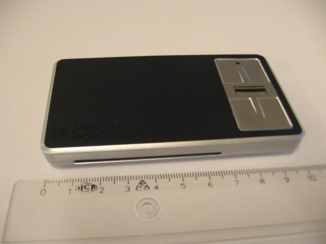
PBKASP1031009
Sep 22, 2011Precise Sense
Equipment Class
JBP - Part 15 Class B Computing Device Peripheral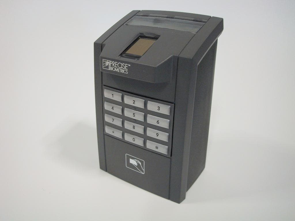
PBKMS010120
Sep 28, 2005Fingerprint Reader
Equipment Class
DXT - Part 15 Low Power Transceiver, Rx Verified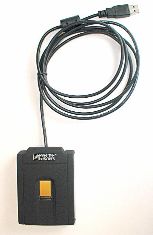
PBKMS010114
Jun 14, 2005Combined Finger Print and Smart Card Reader
Equipment Class
JBP - Part 15 Class B Computing Device Peripheral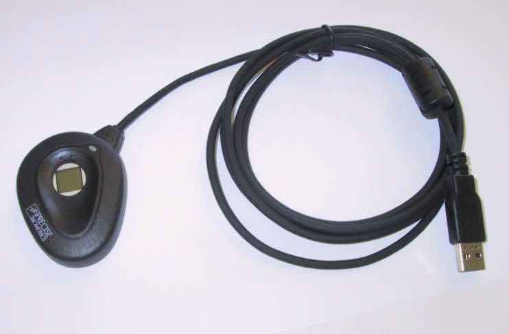
PBKMS010074
Jun 29, 2003Electronic Personnel Identification System
Equipment Class
JBP - Part 15 Class B Computing Device Peripheral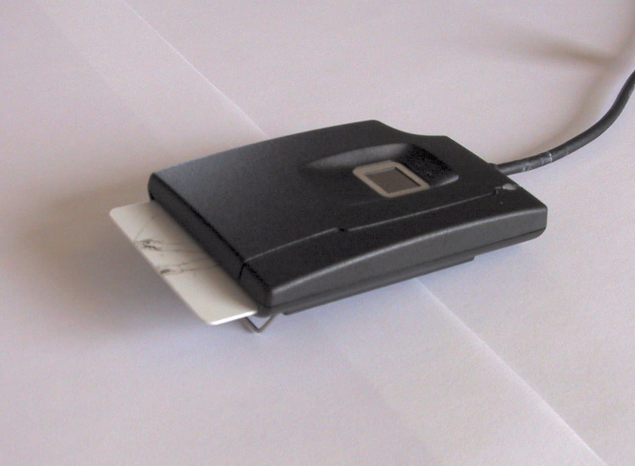
PBKMS010041
May 05, 2002USB Fingerprint Sensor/Smart Card Reader
Equipment Class
JBP - Part 15 Class B Computing Device Peripheral