PBKMS010120Fingerprint Reader
Precise Biometrics AB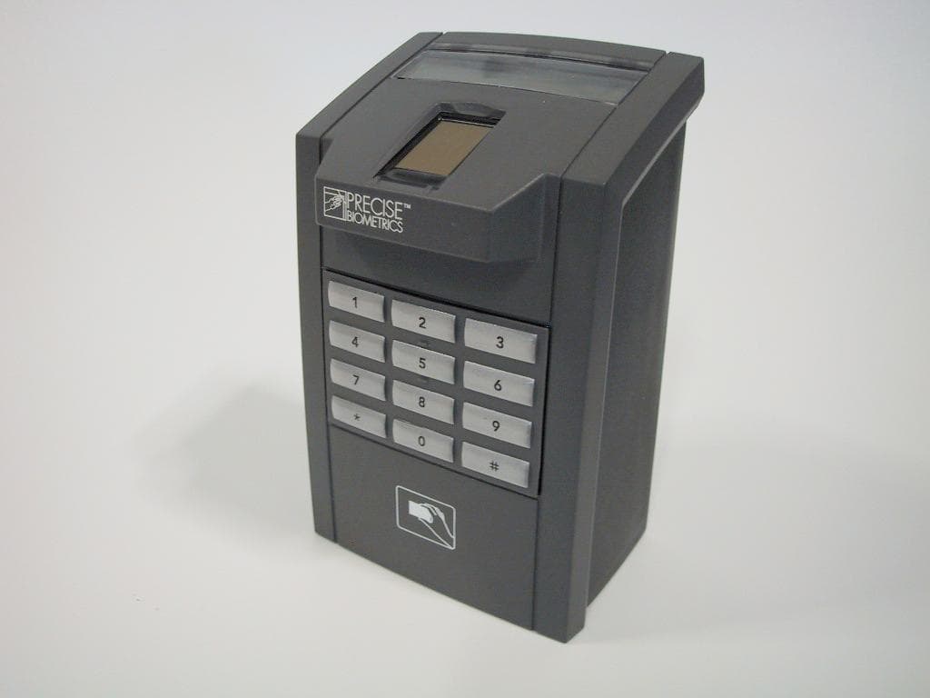
Click to zoom
Application Details
- Equipment Class
- DXT - Part 15 Low Power Transceiver, Rx Verified
- Date of Grant
- Sep 28, 2005
- Application Purpose
- Original Equipment
- Date of Application
- Sep 28, 2005
- Equipment Note
- Fingerprint Reader
- Frequency Range
- 13.56000000 - 13.56000000
- Company
- Precise Biometrics AB
- Country
- Sweden
Documents & Files
Document Text
Text extracted from the exhibit documents filed with the FCC. Open a document above to read the original.
Users Manual
Installation of Precise BioAccess™ 200 Sweden Precise Biometrics AB, Scheelevägen 19 C, SE-223 70 Lund Phone +46 46 31 11 00 Fax +46 46 31 11 01 [email protected] Precise Biometrics AB, Finlandsgatan 66 2 nd floor, SE-164 74 Kista Phone +46 8 632 33 50 Fax +46 8 632 33 55 [email protected] USA Precise Biometrics Inc, 8300 Boone Boulevard, Suite 500, Vienna VA 22182 Phone +1 (703) 848 9266 Fax +1 (703) 832 0577 [email protected] UK Precise Biometrics Ltd, 288 Bishopsgate, London EC2M 4QP Phone +44 (0) 207 959 3060 Fax +44 (0) 207 959 3030 [email protected] www.precisebiometrics.com 1. Connect the wires using a shielded cable. The shielding must be connected to earth at the access control side of the system. BioAccess plint 1 1 Do not connect 2 DATA (magstripe) / DATA 0 (Wiegand) OUTPUT 3 CLOCK (magstripe) / DATA 1 (Wiegand) OUTPUT 4 CARD PRESENT OUTPUT 5 RS485 B 6 RS485 A 7 ground 8 Extra ground 9 Extra ground 10 POWER 12-24 VDC BioAccess plint 2 1 Do not connect 2 Do not connect 3 Do not connect 4 Do not connect 5 RS232 Out 6 RS232 In 7 Do not connect 8 Do not connect 9 Do not connect 10 Do not connect 2. Fasten the holder onto the wall. Recommended mounting height 1.4meter/4.6 feet. 3. Plug the connector(s). Plint 1 should be connected to the left and plint 2 should be connected to the right. Plint 1 Plint 2 4. If the BioAccess reader is going to be connected to an Ethernet, connect the RJ-45 contact. 5. Mount Precise BioAccess™ 200 onto the holder. 6. Secure Precise BioAccess™ 200. Use only screw driver Torx T10. Torque max 1.0 Nm. CE Notice (Europe) This device meets the following technical standards as indicated by the symbol on the device: • EN 55022:1998 Limit B (Radiated emission) • EN 55024:1998 (Immunity of IT-equipment) • EN 61000-6-2:1999 (Immunity for industrial environments) • EN 300 330-2: v.1.1.1 (06-2001) (Radio - spectrum) • EN 301 489-01: v.1.2.1 (07-2000) (Radio - EMC) • EN 301 489-03 (07-2000) (Radio - EMC) FCC Information (USA) This device has been certified to the FCC rules and regulations (CFR47 Part 15 Subpart C) for the low power transmitter contained within this device. In addition, this device has also been verified to comply with Class B digital device requirements as specified in the FCC rules and regulations (CFR47 Part 15 Subpart B). This device complies with Part 15 of the FCC Rules. Operation is subject to the following two conditions: (1) this device may not cause harmful interference, and (2) this device must accept any interference received, including interference that may cause undesired operation. NOTE: This equipment has been tested and found to comply with the limits for a Class B digital device, pursuant to Part 15 of the FCC Rules. These limits are designed to provide reasonable protection against harmful interference in a residential installation. This equipment generates, uses and can radiate radio frequency energy and, if not installed and used in accordance with the instructions, may cause harmful interference to radio communications. However, there is no guarantee that interference will not occur in a particular installation. If this equipment does cause harmful interference to radio or television reception, which can be determined by turning the equipment off and on, the user is encouraged to try to correct the interference by one or more of the following measures: • Reorient or relocate the receiving antenna. • Increase the separation between the equipment and receiver is connected • Connect the equipment into an outlet on a circuit different from that to which the receiver • Consult the dealer or an experienced radio/TV technician for help CAUTION: Changes or modifications not expressly approved by the party
Users Manual
User instructions Precise BioAccess™ 200 Sweden Precise Biometrics AB, Scheelevägen 19 C, SE-223 70 Lund Phone +46 46 31 11 00 Fax +46 46 31 11 01 [email protected] Precise Biometrics AB, Finlandsgatan 66 2 nd floor, SE-164 74 Kista Phone +46 8 632 33 50 Fax +46 8 632 33 55 [email protected] USA Precise Biometrics Inc, 8300 Boone Boulevard, Suite 500, Vienna VA 22182 Phone +1 (703) 848 9266 Fax +1 (703) 832 0577 [email protected] UK Precise Biometrics Ltd, 288 Bishopsgate, London EC2M 4QP Phone +44 (0) 207 959 3060 Fax +44 (0) 207 959 3030 [email protected] www.precisebiometrics.com If you don ́t get in then • Position the finger straight • Try several height positions with the finger • Press harder or softer • Wipe the finger or the sensor • Moist the finger if it ́s to dry • Reenroll. Try another finger 1. Place the card in front of the lower part of BioAccess™ 200. Wait for the green light to the left above the display. The red light indicates a faulty card or a poor reading; try again. Instructions will follow on the display. 2. Position the finger straight onto the finger guide. Follow the instructions given on the display. If pin code is asked for press in your personal pin code. 3. The green light to the right above the display indicates a correct match. If a red light displays, then try again.
Cover Letter(s)
Document No PACS/LET/0003/PB Author Per Ola Olsson Date 2005-09-26 Revision A Page 1/2 Precise Biometrics AB Address: Phone: Fax: E-mail: Org. no.: Bankgiro Ideon Delta 3 +46 46 31 11 00 +46 46 31 11 01 [email protected] 556545-6596 5198-1686 Scheelev. 19C SE-223 70 Lund, Sweden PROJECT PACS TITLE Request for Confidentiality, FCC Name Function Date Checked: Approved: Authorised: 2005-09-26 Paper copies of this document are for reference only. The electronic original is authorised and archived according to GEN/MEM/0003/PB. Document No: PACS/LET/0003/PB Date: 2005-09-26 Revision: A Page: 2/2 The ownership and copyright of this document belongs to Precise Biometrics AB and must not be disclosed, copied, altered or used without the written permission of Precise Biometrics AB. Request for Confidentiality Monday, 26 September 2005 American Telecommunications Certification Body, Inc. 6731 Whittier Avenue Suite C110 McLean, VA 22101 RE: Certification Application FCC ID: PBKMS010120 Please classify the following as confidential under the provision of 47 Cfr Ch.1, Part 15, Subpart B, Class B: • The document “05&06-Block diagram & Product description for FCC.pdf”. • The schematics “07-34-EP010046_C-2.pdf”. The application contains technical information, which Precise Biometrics AB deems to be trade secrets and proprietary. If made public, the information might be used to the disadvantage of the applicant in the market place. Thank you for your attention to this matter. Per Ola Olsson Staff Engineer, hardware development Precise Biometrics AB Scheelevägen 19C SE-223 70 Lund Sweden Phone: +46 (0)46 31 11 06 Cellular: +46 (0)730 35 67 06 Fax: +46 (0)46 31 11 01 E-mail: [email protected]
ID Label/Location Info
Label location and sample
Test Report
1 Page: 1of 7 TEST REF. NO: 05/2102A DATE: August 31, 2005 TEST REPORT REPORT CERTIFICATE issued by a FCC listed Test Laboratory CUSTOMER AND Project no: 05263 MANUFACTURER: Precise Biometrics AB Scheelevägen 19 C SE-223 70 Lund Sweden EQUIPMENT UNDER TEST (EUT): Combined Fingerprint and Mi Fare contactless card Reader, Type Bio Access 200, s/n EMC Unit 1, V2. TEST SPEC: 47 Cfr Ch. 1 (10-1-04 Edition): Transmitter, Part 15, Subpart C: §15.225, Operation within the band 13.110 – 14.010 MHz Digital Device, Part 15, Subpart B, Class B. §15.107: Conducted Emission, AC power line §15.109: Radiated Emission DATE OF TEST: August 18, 2005 TEST SITE: Svenska EMC Lab AB, Karlskrona, Sweden. FCC registration number: 90967. CONFORMITY: The EUT (Equipment Under Test), did pass the above mentioned tests. The test result shows full compliance with the above technical specifications provided modification steps outlined in this report are taken. ----------------------------------------------------------------------------------------------------------- Approved, Karlskrona August 31, 2005 ................................................... Hans Östergren Manager Svenska EMC Lab AB This report may not be reproduced other than in full, except with the prior written approval of Svenska EMC Lab AB. 2 Page: 2 of 7 TEST REF. NO: 05/2102A DATE: August 31, 2005 ------------------------------------------------------------------------------------------------------------------------ DATE OF RECEIPT: August 17, 2005 CONDITION OF EUT: No remarks. Operates as intended. TEST PERSONNEL: Svenska EMC Lab AB: Hans Östergren. ASSISTANT PERSONNEL: Precise Biometrics AB: Per Ola Olsson, Niklas Brogden, Jan-Peter Nilsson. DESCRIPTION OF THE EUT: The EUT is a combined fingerprint and Mi Fare contactless card reader that offers security for access control. It compared fingerprint with a template stored in a Mi Fare card to provide personal proof that people entering premises are who they claim to be. The EUT has interface to one of the following ports: Data/Clock (Magstripe) and Wiegand, RS485, RS232 and Ethernet. The Mifare fundamental frequency is 13.56 MHz. EUT size: 125 x 68 x 61 mm / 4.9 x 2.7 x 2.4 inches (H x W x D) ESTIMATED UNCERTAINTY: Expanded uncertainty (k = 2): Conducted Emission, 0.15 – 30 MHz: ± 1.1 dB Field Strength, emission 0.009 – 30 MHz: ± 2.8 dB Field Strength, emission 30 – 300 MHz: ± 2.2 dB Field Strength, emission 300 – 700 MHz: ± 2.3 dB Field Strength, emission 700 – 1300 MHz: ± 2.4 dB Field Strength, emission 1 to 10 GHz: ± 3.0 dB Frequency, 0.009 – 30 MHz: ± 1 Hz Frequency, 30 – 1000 MHz: ± 10 Hz Frequency, 1 – 10 GHz: ± 100 Hz Temperature: ± 0.2 °C Voltage, DC: ± 0.01 % The uncertainties are for a confidence level of not less than 95 %. 3 Page: 3 of 7 TEST REF. NO: 05/2102A DATE: August 31, 2005 ------------------------------------------------------------------------------------------------------------------------ TEST EQUIPMENT LIST: Type/Manufacturer/Bandwidth s/n Calibration information Date Interval EMI Test System, Monitor EZM, 860157/014 2004-07 12 months Rohde & Schwarz EP-6, 20 Hz - 1300 MHz Test Receiver, Rohde & Schwarz ESH-3, 894979/013 2004-07 12 months 9 kHz - 30 MHz Test Receiver, Rohde & Schwarz ESVP, 893497/006 2004-07 12 months 20 - 1300 MHz Pulse Limiter, Rohde & Schwarz ESH3-Z2 357881052 2004-07 12 months DC - 30 MHz Plotter, Rohde & Schwarz DOP 2 893117/0108 NA NA LISN 50 OHM/50 μH, Electro Metrics EM-7820 2771 2004-07 12 months 10 kHz - 30 MHz, 16 A LISN 50 OHM/50 μH, MEB NNB-4/200 C96001/3 2004-07 12 months 0.15 - 30 MHz, 200 A Cable to Test Receiver, RG 223 006 2004-08 12 months Cable to LISN, RG 223 015 2004-08 12 months Loop Antenna, EMCO 6502, 9 kHz - 30 MHz 1057 2004-05 24 months Biconical Antenna, Schwarzbeck BBA9106 93-92196.1 2004-07 24 months 30 - 300 MHz Log-periodic Antenna, Schwarzbeck 91071205 2004-07 24 months UHALP9107, 300 - 1000 MHz Double Ridged Guide Antenna, EMCO 3115, 2338 2003-09 36 months 1 - 18 GHz Spectrum Analyzer Tektronix 2755AP, B010111 2005-07 12 months 10 kHz - 21 GHz Preamplifier, Mini-Circuits ZHL-42, 860701 2005-02 12 months 0.7 – 4.2 GHz Antenna Cable, H-100 024 2004-08 12 months Coaxial Cable, Sucoflex 104, l = 0.5 m 180067/4 2004-08 12 months Coaxial Cable, Sucoflex 104, l = 5 m 171288/4 2004-08 12 months Antenna Mast System, Jyske EMC, h = 1 - 4 m 02 NA NA Turn Table, Jyske EMC, h = 1 m 01 NA NA Shielded Chamber, Jyske EMC, 11 x 6 x 4.5 m 3 0003 36 months Anechoic Chamber, 8 x 4.5 x 3 m 1 2003-04 36 months Open Area Test Site for 3 m antenna distance 1 2003-12 36 months DC Power Supply, Mascot , 0 – 30 V, 1.5 A 719 NA NA Digital Multimeter, Fluke 77 63430754R 2004-02 24 months Temperature chamber, Weis Technich GmBh, 211/10182 NA NA Type KWP 30/80-180 DU 4 Page: 4 of 7 TEST REF. NO: 05/2102A DATE: August 31, 2005 ------------------------------------------------------------------------------------------------------------------------ TEST SET-UP AND PROCEDURE: See Appendix 1 to 3. As laid out in ANSI C.63.4:2001 Document. STANDARDS: The EUT is designed with both digital circuits and a radio transmitter. Applicable parts in 47 Cfr Ch. 1 (10-1-04 Edition) are for the Transmitter: Part 15, Subpart C: §15.225, Operation within the band 13.110 – 14.010 MHz Digital Device: Part 15, Subpart B, Class B. §15.107: Conducted Emission, AC power line §15.109: Radiated Emission TEST CONDITIONS: Rating: 12 – 30 VDC, 0.3 A. Tested with 16 V. Power Supply: 115VAC/16VDC Power Supply, IBM p/n 02K6543: Output 16 VDC 4.5 A. Fundamental frequency: 13.56 MHz. Effective radiated power: < 1 mW. Transmitting: Data length 1 second. Repetition time 6 seconds. Operating Conditions: Activated fingerprint and contactless Mifare card (RF powered tag). The transmitter was continuously operating at 1 sec. on and 5 sec. off during the emission tests. Measured frequency range: 9 kHz – 2 000 MHz. Antenna: Fixed PCB Antenna. No external Antenna contact. Clock Frequency: 12.0 MHz, 2…
Text truncated - open the document above for the full version.
Test Setup Photos
Appendix 1 of 8 TEST REF. NO: 05/2102A DATE: August 31, 2005 ------------------------------------------------------------------------------------------------------------------------ Test set-up, Conducted Emission Test set-up, Conducted Emission Appendix 2 of 8 TEST REF. NO: 05/2102A DATE: August 31, 2005 ------------------------------------------------------------------------------------------------------------------------ Test set-up, Radiated Emission
Contact Information
Applicant
Per-Ola Olsson(Staff Engineer, Hardware Development)
Technical Contact
Test Firm
Svenska EMC Lab ABHans Ostergren
Technical Specifications
| # | Rule Parts | Frequency Range | Power Output |
|---|---|---|---|
| 1 | 15C | 13.56 MHz - 13.56 MHz | - |
Other Applications from Precise Biometrics AB
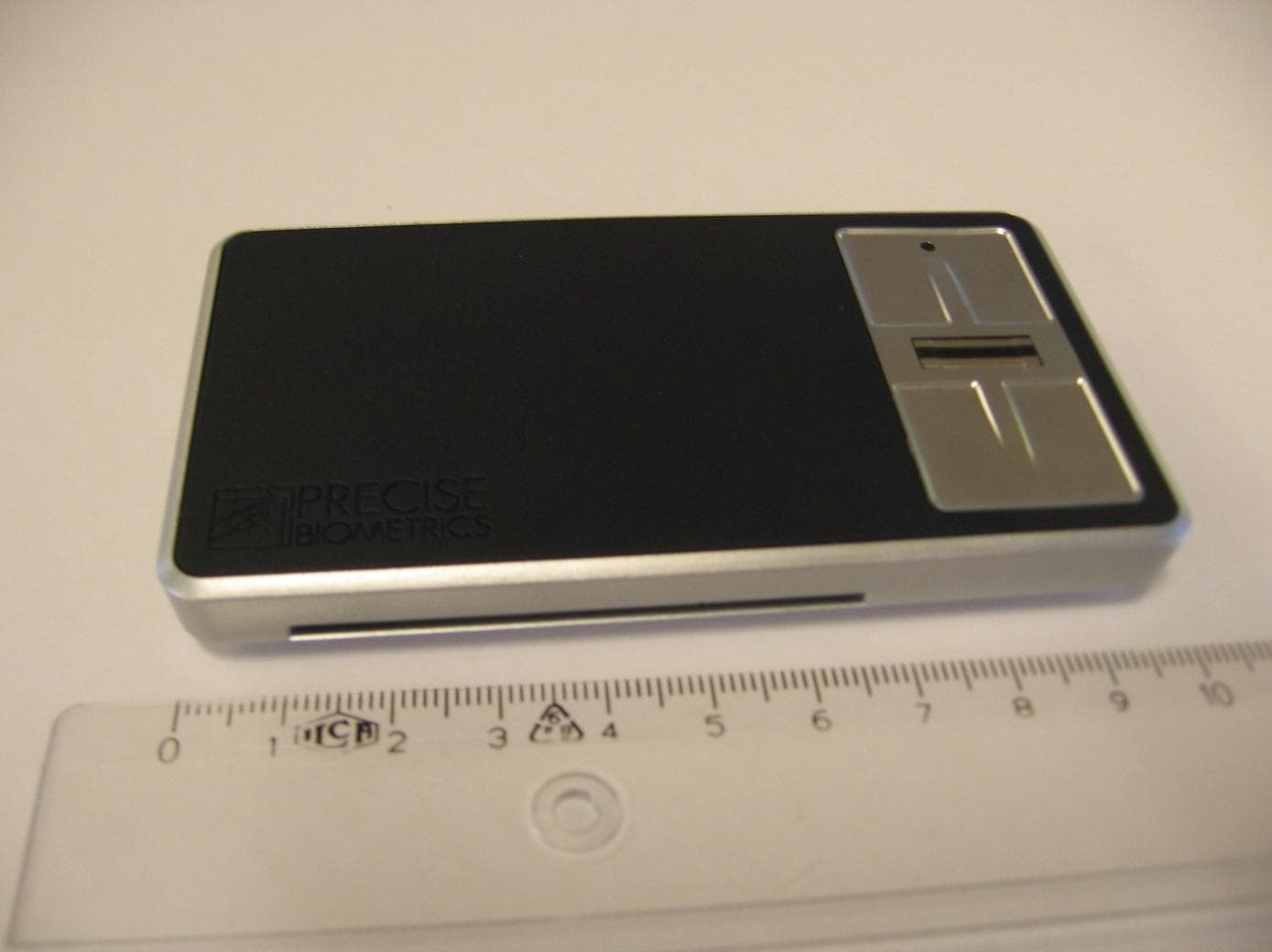
PBKASP1031009
Sep 22, 2011Precise Sense
Equipment Class
JBP - Part 15 Class B Computing Device Peripheral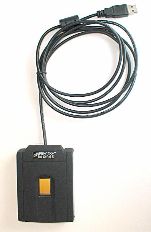
PBKMS010114
Jun 14, 2005Combined Finger Print and Smart Card Reader
Equipment Class
JBP - Part 15 Class B Computing Device Peripheral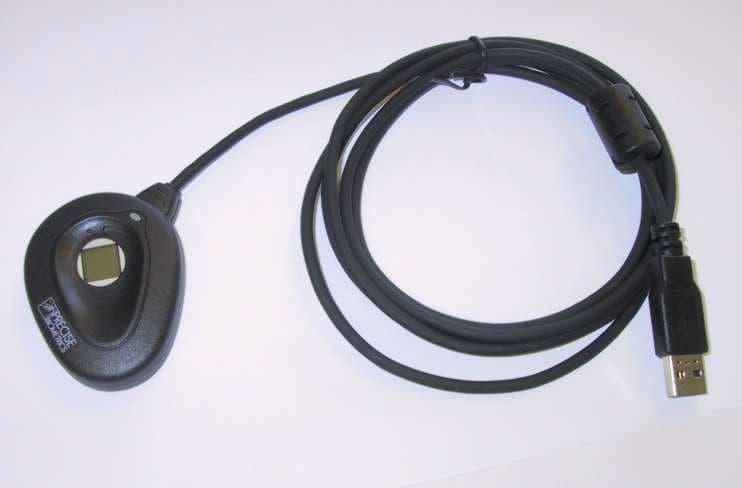
PBKMS010074
Jun 29, 2003Electronic Personnel Identification System
Equipment Class
JBP - Part 15 Class B Computing Device Peripheral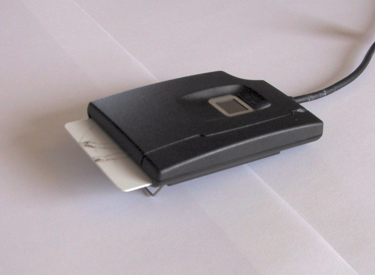
PBKMS010041
May 05, 2002USB Fingerprint Sensor/Smart Card Reader
Equipment Class
JBP - Part 15 Class B Computing Device Peripheral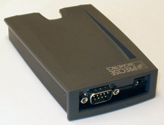
PBKMS010040
Mar 08, 2002Smart card
Equipment Class
DXX - Part 15 Low Power Communication Device Transmitter