PBKMS010041USB Fingerprint Sensor/Smart Card Reader
Precise Biometrics AB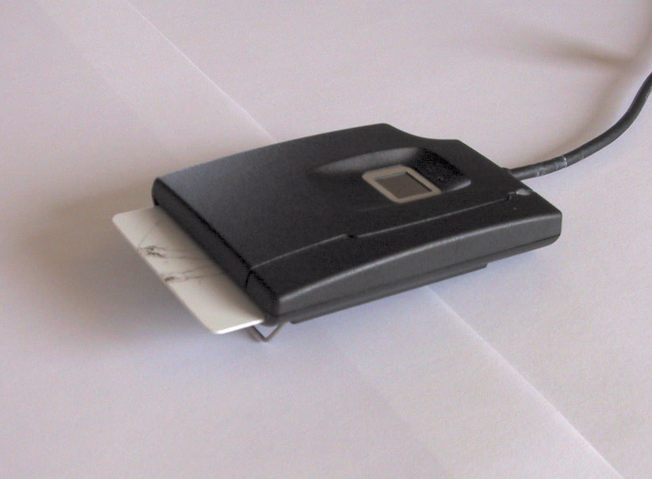
Click to zoom
Application Details
- Equipment Class
- JBP - Part 15 Class B Computing Device Peripheral
- Date of Grant
- May 05, 2002
- Application Purpose
- Original Equipment
- Date of Application
- May 05, 2002
- Equipment Note
- USB Fingerprint Sensor/Smart Card Reader
- Company
- Precise Biometrics AB
- Country
- Sweden
Documents & Files
Document Text
Text extracted from the exhibit documents filed with the FCC. Open a document above to read the original.
Users Manual
Document No ALI4/LET/0012/PB Date 2002-03-21 Revision B Page 1/1 Precise Biometrics AB Address: Phone: Fax: E-mail: WWW: Dag Hammarskjölds väg 2 +46(46)311100 +46(46)311101 [email protected] www.precisebiometrics.com SE-224 64 Lund, Sweden FCC statements for Precise 100 MC Fingerprint reader Statements The following statements will be included in the Quick Reference or equivalent delivered with the product: This device complies with Part 15 of the FCC Rules. Operation is subject to the following two conditions: (1) this device may not cause harmful interference, and (2) this device must accept any interference received, including interference that may cause undesired operation. NOTE: This equipment has been tested and found to comply with the limits for a Class B digital device, pursuant to Part 15 of the FCC Rules. These limits are designed to provide reasonable protection against harmful interference in a residential installation. This equipment generates, uses and can radiate radio frequency energy and, if not installed and used in accordance with the instructions, may cause harmful interference to radio communications. However, there is no guarantee that interference will not occur in a particular installation. If this equipment does cause harmful interference to radio or television reception, which can be determined by turning the equipment off and on, the user is encouraged to try to correct the interference by one or more of the following measures: • Reorient or relocate the receiving antenna. • Increase the separation between the equipment and receiver. • Connect the equipment into an outlet on a circuit different from that to which the receiver is connected. • Consult the dealer or an experienced radio/TV technician for help. CAUTION: Changes or modifications not expressly approved by the party responsible for compliance could void the user`s authority to operate the equipment.
Cover Letter(s)
Document No ALI4/LET/0019/PB Date 2002-04-23 Revision A Page 1/1 Precise Biometrics AB Address: Phone: Fax: E-mail: WWW: Dag Hammarskjölds väg 2 +46(46)311100 +46(46)311101 [email protected] www.precisebiometrics.com SE-224 64 Lund, Sweden Variant of Precise 100 MC fingerprint reader with short USB cable The radiated emission tests of the Precise 100 MC fingerprint reader were performed using a Precise 100 MC device with a long (2.0 m) USB cable. The Precise 100 MC also exists in a variant with a short (0.4 m) USB cable. Since a long cable is worse than a short cable regarding radiated emission, we only tested the long cable variant at the DELTA Electronics test lab. However, we have performed measurements our selves that confirms that the short cable variant is not a worse emitter than the long cable variant. We intend to use the same FCC ID for the long and the short cable variant of the Precise 100 MC fingerprint reader.
Cover Letter(s)
Document No ALI4/LET/0016/PB Author Håkan Lohmander Date 2002-03-21 Revision A Page 1/1 Precise Biometrics AB Address: Phone: Fax: E-mail: WWW: Dag Hammarskjölds väg 2 +46(46)311100 +46(46)311101 [email protected] www.precisebiometrics.com SE-224 64 Lund, Sweden Request for Confidentiality Thursday, 21 March 2002 American Telecommunications Certification Body, Inc. 6731 Whittier Avenue Suite C110 McLean, VA 22101 RE: Certification Application FCC ID: PBKMS010041 Please be advised that the following information is to be held confidential on behalf of Precise Biometrics AB: • Schematics • Block Diagram • Bill of Materials (Parts List) • Circuit description and statement of how the device operates The application contains technical information, which Precise Biometrics AB deems to be trade secrets and proprietary. If made public, the information might be used to the disadvantage of the applicant in the market place. Thank you for your attention to this matter. Håkan Lohmander
Cover Letter(s)
American Telecommunications Certification Body Inc. 6731 Whittier Ave, McLean, VA 22101 May 1, 2002 RE: Precise Biometrics AB FCC ID: PBKMS010041 After a review of the submitted information, I have a few comments on the above referenced Application. 1) Please provide a block diagram that includes the frequencies as specified in CFR 2.1033(a)(5). Also see issue 7 below. 2) The EUT receives its power from a host piece of equipment (in this case a laptop) and therefore conducted emissions data needs to be provided (see 15.107(f)). Be sure that the conducted emissions setup is consistent with the procedure specified by ANSI C63.4 (i.e. location of LISN, presence of vertical ground plane, etc.). Please provide new test data and photographs for this. 3) The external photographs do not appear to show a connection for the Smart Card Reader. Please provide an additional photograph showing the contacts and/or placement of the card when used. Additionally, please confirm whether this is a contact Smart Card reader or wireless type card reader. 4) The label appears to have plenty of space available and therefore should also include the statements specified by 15.19(a)(3). 5) The 2 internal photographs provided are too dark and the resolution is lower than desired. Please provide new internal photos. 6) You provided a letter addressing 2 different cable lengths. The external photographs show a ferrite on the USB cable (near to the PC connection side). Please confirm if this ferrite will be attached to both cable types offered. 7) The schematics show 2 additional oscillators at 14.7456 & 7.3728 MHz that do not appear to be in the parts list. Please explain. The block diagram also only shows 2 oscillators instead of 4. 8) The test report shows data at 1 & 4 meter antenna heights. For final maximized readings, the antenna should be raised and lowered between 1 & 4 meters to obtain worse case positioning. Please comment on if the antenna positioned was swept between 1 & 4 meters. 9) Please confirm that the EUT was rotated about 360 degrees to obtain worse case azimuth during the test. 10) FYI, For future applications, please be careful in positioning of devices classified as PC peripheral devices. These devices typically require a 10 cm spacing from the host unit. Although the FCC alternatively allows use of the limits from EN55022/CISPR 22 the procedure/setup must still follow ANSI C63.4 (see 15.109(g)(1)). Timothy R. Johnson Examining Engineer mailto: [email protected] The items indicated above must be submitted before processing can continue on the above referenced application. Failure to provide the requested information may result in application termination. Correspondence should be considered part of the permanent submission and may be viewed from the Internet after a Grant of Equipment Authorization is issued. Please do not respond to this correspondence using the email reply button. In order for your response to be processed expeditiously, you must submit your documents through the AmericanTCB.com website. Also, please note that partial responses increase processing time and should not be submitted. Any questions about the content of this correspondence should be directed to the sender.
Cover Letter(s)
2002-05-03 peh/aed A0229/2002 DELTA Danish Electronics, Light & Acoustics Venlighedsvej 4 2970 Hørsholm Denmark Tel. (+45) 72 19 40 00 Fax (+45) 72 19 40 01 www.delta.dk VAT DK 12275110 To: Reviewing Engineer Ref: FCC ID PBKMS010041 (Precise Biometrics AB) DELTA project K222311-1 Replies to Comments covering points 2, 8 and 9 of letter from ATCB dated May 1, 2002. Comment (2): The EUT receives its power from a host piece of equipment (in this case a laptop) and therefore conducted emissions data need to be provided (see 15.107(f)). Be sure that the conducted emissions set-up is consistent with the procedure specified by ANSI C63.4 (i.e. location of LISN, presence of ver- tical ground plane, etc.). Please provide new test data and photographs for this. Reply (2):A test of AC mains conducted emission at the laptop power line will addi- tionally be performed. A revised DELTA test report (project K222311-1- Rev.A, DANAK-196163) will be issued. Comment (8): The test report shows data at 1 & 4 meter antenna heights. For final maxi- mised readings, the antenna should be raised and lowered between 1 & 4 meter to obtain worse case positioning. Please comment on if the antenna positioned was swept between 1 & 4 meters. Reply (8):The accredited DELTA compliant measurements are performed according to the requirements of FCC part 15.31 (ANSI C63.4-1992). The ANSI C63.4: 1992 part 8.2.3 prescribes that the antenna height is varied between 1 meter and 4 meters. On the relevant DELTA test record sheets the table gives the values for the maximised readings. The antenna height, the antenna polari- sation and the azimuth readings are given for worse case positions. Comment (9): Please confirm that the EUT was rotated about 360 degrees to obtain worse case azimuth during the test. Reply (9):We confirm that the EUT during the test was rotated about 360 degrees to obtain worse case azimuth. See also Reply (8). Yours sincerely DELTA Per Hansen Project manager
Cover Letter(s)
Document No ALI4/LET/0021/PB Author Håkan Lohmander Date 2002-05-02 Revision A Page 1/2 Precise Biometrics AB Address: Phone: Fax: E-mail: WWW: Dag Hammarskjölds väg 2 +46(46)311100 +46(46)311101 [email protected] www.precisebiometrics.com SE-224 64 Lund, Sweden To: Reviewing Engineer Ref: FCC ID: PBKMS010041 Reply to comments in letter "ATCB Comment_050102.pdf" Comment: The external photographs do not appear to show a connection for the Smart Card Reader. Please provide an additional photograph showing the contacts and/or placement of the card when used. Additionally, please confirm whether this is a contact Smart Card reader or wireless type card reader. Reply: Additional external photograph of placement of the card when the device is in use will be provided. The device is a contact smart card type reader. Comment: The label appears to have plenty of space available and therefore should also include the statements specified by 15.19(a)(3). Reply: Additional information has to be printed on the label as well. For example the label will include UL-logo, CE-logo, plain text etc. When this information has been printed on the label there is no space left for the statement specified by 15.19(a)(3). However, the information of 15.19(a)(3) will be placed in the users manual as stipulated by 15.19(a)(5). The design of the device does not permit additional labels. Comment: You provided a letter addressing 2 different cable lengths. The external photographs show a ferrite on the USB cable (near to the PC connection side). Please confirm if this ferrite will be attached to both cable types offered. Reply: Both cable types will have a ferrite attached. Document No: ALI4/LET/0021/PB Date: 2002-05-02 Revision: A Page: 2/2 The ownership and copyright of this document belongs to Precise Biometrics AB. It must not be disclosed, copied, altered or used without the written permission of Precise Biometrics AB. Comment: The schematics show 2 additional oscillators at 14.7456 & 7.3728 MHz that do not appear to be in the parts list. Please explain. The block diagram also only shows 2 oscillators instead of 4. Reply: The oscillators X3 (7.3728Mhz) and X1 (14.7456MHz) are not mounted in this product. They can be mounted for other products. We can make several different products with the same PCB and just use different part lists. However, if a new product is produced using this PCB it will be submitted in the form of a permissive change (to the existing application) or under a new FCC ID number. Håkan Lohmander Project Manager
External Photos
Document No ALI4/LET/0011/PB Date 2002-05-02 Revision C Page 1/4 Precise Biometrics AB Address: Phone: Fax: E-mail: WWW: Dag Hammarskjölds väg 2 +46(46)311100 +46(46)311101 [email protected] www.precisebiometrics.com SE-224 64 Lund, Sweden External photographs of Precise 100 MC Document No: ALI4/LET/0011/PB Date: 2002-05-02 Revision: C Page: 2/4 The Precise 100 MC reader The Precise 100 MC reader with inserted smart card Document No: ALI4/LET/0011/PB Date: 2002-05-02 Revision: C Page: 3/4 The Precise 100 MC reader Document No: ALI4/LET/0011/PB Date: 2002-05-02 Revision: C Page: 4/4 The Precise 100 MC reader
ID Label/Location Info
Document No ALI4/LET/0013/PB Author Håkan Lohmander Date 2002-01-03 Revision A Page 1/2 Precise Biometrics AB Address: Phone: Fax: E-mail: WWW: Dag Hammarskjölds väg 2 +46(46)311100 +46(46)311101 [email protected] www.precisebiometrics.com SE-224 64 Lund, Sweden FCC ID Label Location and Information for Precise 100 MC Fingerprint Reader Document No: ALI4/LET/0013/PB Date: 2002-01-03 Revision: A Page: 2/2 Label size: Ca 39 mm x ca 29 mm. Label type: Self-adhesive label. UL Marked. FCC text: PBKMS010041. FCC font: 8 point Helvetica Neue Cond. Below: Drawing of label to be placed on backside of reader. Position of label on backside of reader FCC ID: PBKMS010041 Ca 29 mm Ca 39 mm FCC ID: PBKMS010041FCC ID: PBKMS010041 Ca 29 mm Ca 39 mm
Internal Photos
Document No ALI4/LET/0018/PB Date 2002-05-02 Revision B Page 1/2 Precise Biometrics AB Address: Phone: Fax: E-mail: WWW: Dag Hammarskjölds väg 2 +46(46)311100 +46(46)311101 [email protected] www.precisebiometrics.com SE-224 64 Lund, Sweden Internal Photographs of Precise 100 MC Document No: ALI4/LET/0018/PB Date: 2002-05-02 Revision: B Page: 2/2 Front Back
Test Report
20dan-uk-i D E LTA Danish Electronics, Light & Acoustics Venlighedsvej 4 DK-2970 Hørsholm Denmark Tel. (+45) 72 19 40 00 Fax (+45) 72 19 40 01 www.delta.dk This report is issued under the rules of DANAK (Danish Accreditation). Further information about DANAK can be found at www.danak.dk. The report must not be reproduced, except in full, without the written approval of DELTA. Test Report DANAK Reg. no. 19 EMC test of Precise 100 MC Performed for Precise Biometrics AB DANAK-196163 Project no.: K222311-1 - Rev. A Page 1 of 16 6 annexes 2002-05-13 DANAK-196163 DELTA-K222311-1 - Rev. A Page 2 of 16 PEH/blj Title EMC test of Precise 100 MC Test object Precise 100 MC fingerprint reader Report no. DANAK-196163 Project no. K222311-1 - Rev. A Test period 2002-03-15 to 2002-05-03 Client Precise Biometrics AB Dag Hammerskjöldsväg S-224 64 Lund Sweden Telephone: +46 46 311100 Fax: +46 46 311101 Contact person Mr. Jörgen Lindell Manufacturer Precise Biometrics AB Specifications EN 55022:1998 FCC Rules and Regulations, Part 15, Subpart B, demon- strated by compliance with EN 55022:1998 EN 55024:1998 Results During the performed immunity tests, comprising test of immunity to radiated electromagnetic field, burst transients and electrostatic discharges, no malfunctions were detected. The criteria for compliance are listed in section 3.2. The AC mains conducted emission and radiated electro- magnetic field were within the specifications. Test personnel Poul Nørgaard Jesper Nielsen DANAK-196163 DELTA-K222311-1 - Rev. A Page 3 of 16 PEH/blj Date 2002-05-13 Project manager Per Hansen Facility Manager - EMC DELTA Responsible Per Thåstrup Jensen Project Manager - EMC DELTA DANAK-196163 DELTA-K222311-1 - Rev. A Page 4 of 16 PEH/blj Table of contentsPage 1.Summary of test5 2.Test specimens6 2.1Test object - Precise 100 MC6 2.2AUX equipment - Laptop PC6 2.3AUX equipment - AC adapter6 3.General test conditions7 3.1Test set-up7 3.2Criteria for compliance during immunity tests8 3.3Monitoring during immunity tests8 4.Test and results9 4.1Immunity to radiated electromagnetic field - EN 61000-4-3:1996 + A19 4.2Immunity to electrostatic discharge (ESD) - EN 61000-4-2:1995 + A110 4.3Immunity to electrical fast transients (Burst) - EN 61000-4-4:199512 4.4Radiated electromagnetic field - EN 55022:1998, Class B13 4.5Radiated electromagnetic field - FCC Rules and Regulations Part 15:1998 Subpart B, Class B demonstrated by compliance with EN 55022 (CISPR22)14 4.6AC mains conducted emission - EN 55022:1998, Class B15 4.7AC mains conducted emission - FCC Rules and Regulations Part 15:1998 Subpart B, Class B demonstrated by compliance with EN 55022 (CISPR22)16 Annex 1 List of instruments (1 page) Annex 2 Photos regarding immunity tests (5 pages) Annex 3 Test record sheets and photos regarding measurements of radiated electromagnetic fields EN 55022 (6 pages) Annex 4 Test record sheets and photos regarding measurements of radiated electromagnetic fields FCC (6 pages) Annex 5 Test record sheets and photos regarding measurements of AC mains conducted emission EN 55022 (6 pages) Annex 6 Test record sheets and photos regarding measurements of AC mains conducted emission FCC (6 pages) DANAK-196163 DELTA-K222311-1 - Rev. A Page 5 of 16 PEH/blj 1. Summary of test TestTest methodComments Radio frequency electromagnetic fieldEN 61000-4-3:1996+A1Passed Electrostatic dischargesEN 61000-4-2:1995+A1Passed Electrical fast transientsEN 61000-4-4:1995Passed Radiated electromagnetic fieldEN 55022:1998, Class B (CISPR22:1997), Class B Passed Radiated electromagnetic fieldFCC Rules and Regulations, Part 15, Subpart B, Class B Passed AC mains conducted emissionEN 55022:1998, Class B (CISPR22:1997), Class B Passed AC mains conducted emissionFCC Rules and Regulations, Part 15, Subpart B, Class B Passed Conclusion The test object mentioned in this report meets the requirements of the standards stated below. • EN 55022:1998, Class B • FCC Rules and Regulations, Part 15, Subpart B, Class B • EN 55024:1998 (in part). The test results relate only to the specimen tested. DANAK-196163 DELTA-K222311-1 - Rev. A Page 6 of 16 PEH/blj 2. Test specimens 2.1 Test object - Precise 100 MC CategoryFingerprint reader ManufacturerPrecise Biometrics AB Model / typePrecise 100 MC Part no.- Serial no.#2 FCC ID- Supply voltage5.0 VDC. Power was supplied through the USB cable from the laptop PC. During the immunity tests the laptop PC was power supplied with 230 VAC. During the AC mains conducted emission test and ra- diated electromagnetic field test the PC was power supplied with 115 VAC. Operational modeTests were performed in 2 modes: 1) Scanning fingerprint mode 2) Reading smartcard mode. SoftwareThe laptop PC was running a software reading from fingerprint reader and registrating the read fingerprint. For each registered fingerprint an indication was given on the laptop PC monitor. This indication was one stroke per registration (/ \ / \ / \ / etc). CommentsDuring the tests in scanning fingerprint mode an artificial finger was used to ensure continuous activity of the scanning procedure. 2.2 AUX equipment - Laptop PC ManufacturerIBM Model / type2545-4BG Part no.- Serial no.5528TVC 02/99 FCC IDTested to comply with FCC standards 2.3 AUX equipment - AC adapter ManufacturerIBM Model / type1ZORV860PF Part no.- Serial no.- FCC IDTested to comply with FCC standards DANAK-196163 DELTA-K222311-1 - Rev. A Page 7 of 16 PEH/blj 3. General test conditions 3.1 Test se t -up Precise 100 MC EUT 2.1 Illustrated with smartcard inserted AC adapter AUX 2.3 Laptop PC AUX 2.2 115 VAC / 230 VAC USB-cable. 2 m. Shielded Power cable.2 m. Unshielded Power cable. 1 m. Unshielded Smartcard DANAK-196163 DELTA-K222311-1 - Rev. A Page 8 of 16 PEH/blj 3.2 Criteria for compliance during immunity tests During test in fingerprint scanning mode the scanning process shall continue to operate. Dur- ing test in smartcard reading mode the registration of card information must not fail. Generally no degrada…
Text truncated - open the document above for the full version.
Test Setup Photos
DANAK-196163 DELTA-K222311-1 - Rev. A This exhibit is an extract of DELTA Test Report K222311-1 - Rev. A, DANAK-196163, containing only the photographs of representative test set-ups. DANAK-196163 DELTA-K222311-1 - Rev. A Photo A2.1Radiated electromagnetic field test with test object in fingerprint scanning mode Photo A2.2Radiated electromagnetic field test with test object in fingerprint scanning mode DANAK-196163 DELTA-K222311-1 - Rev. A Photo A2.3Radiated electromagnetic field test with test object in smartcard mode Photo A2.4Radiated electromagnetic field test with test object in smartcard mode DANAK-196163 DELTA-K222311-1 - Rev. A Photo A2.5Burst transient test Photo A2.6Electrostatic discharges on vertical coupling plane DANAK-196163 DELTA-K222311-1 - Rev. A Photo A2.7Electrostatic discharges general test set-up Photo A2.8Test object in smartcard reading mode DANAK-196163 DELTA-K222311-1 - Rev. A Photo A2.9Test object in fingerprint scanning mode DANAK-196163 DELTA-K222311-1 - Rev. A Photo A3.1Radiated electromagnetic field test. Test object in fingerprint scanning mode Photo A3.2Radiated electromagnetic field test. Test object in fingerprint scanning mode DANAK-196163 DELTA-K222311-1 - Rev. A Photo A3.3Radiated electromagnetic field test. Test object in smartcard reading mode Photo A3.4Radiated electromagnetic field test. Test object in smartcard reading mode DANAK-196163 DELTA-K222311-1 - Rev. A Photo A4.1Radiated electromagnetic field test. Test object in fingerprint scanning mode Photo A4.2Radiated electromagnetic field test. Test object in fingerprint scanning mode DANAK-196163 DELTA-K222311-1 - Rev. A Photo A4.3Radiated electromagnetic field test. Test object in smartcard reading mode Photo A4.4Radiated electromagnetic field test. Test object in smartcard reading mode DANAK-196163 DELTA-K222311-1 - Rev. A Photo A5.1AC mains conducted emission. Test object in smartcard reading mode. Photo A5.2AC mains conducted emission. Test object in smartcard reading mode DANAK-196163 DELTA-K222311-1 - Rev. A Photo A5.3AC mains conducted emission. Test object in fingerprint scanning mode Photo A5.4AC mains conducted emission. Test object in fingerprint scanning mode DANAK-196163 DELTA-K222311-1 - Rev. A Photo A6.1AC mains conducted emission. Test object in smartcard reading mode Photo A6.2AC mains conducted emission. Test object in smartcard reading mode DANAK-196163 DELTA-K222311-1 - Rev. A Photo A6.3AC mains conducted emission. Test object in fingerprint scanning mode. Photo A6.4AC mains conducted emission. Test object in fingerprint scanning mode
Contact Information
Applicant
Per-Ola Olsson(Staff Engineer, Hardware Development)
Technical Contact
Precise BiometricsHakan Lohmander
[email protected]+46 46 31 11 00
Dag Hammarskjoldsvag 2 · Lund · Sweden
Non-Technical Contact
Preceise BiometricsHakan Lohmander
[email protected]+46 46 31 11 00
Test Firm
DELTA Electronic TestingJorgen Christensen
Technical Specifications
| # | Rule Parts | Frequency Range | Power Output |
|---|---|---|---|
| 1 | 15B | - | - |
Other Applications from Precise Biometrics AB
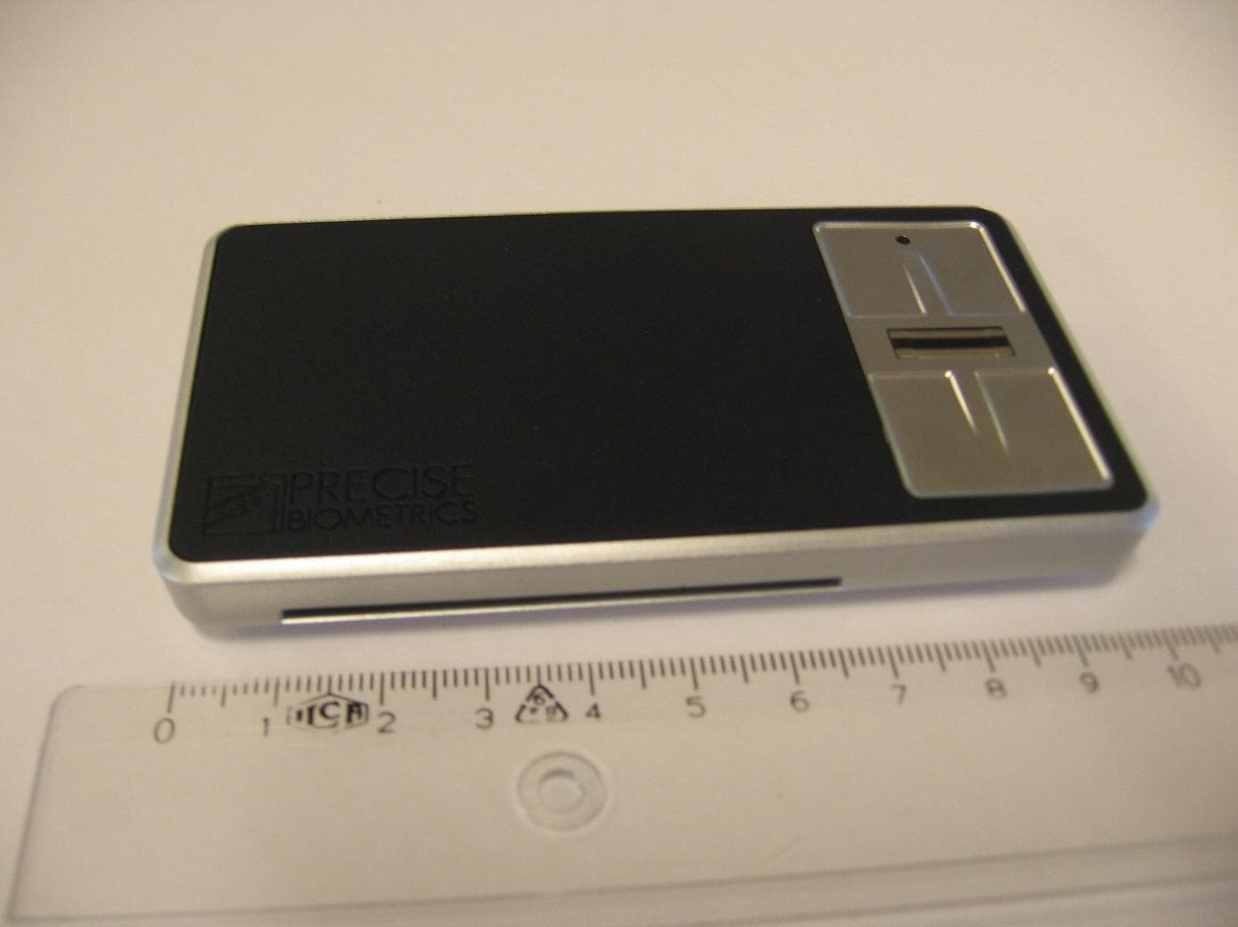
PBKASP1031009
Sep 22, 2011Precise Sense
Equipment Class
JBP - Part 15 Class B Computing Device Peripheral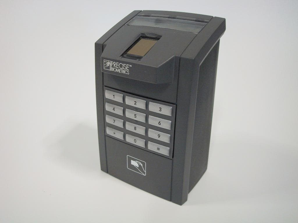
PBKMS010120
Sep 28, 2005Fingerprint Reader
Equipment Class
DXT - Part 15 Low Power Transceiver, Rx Verified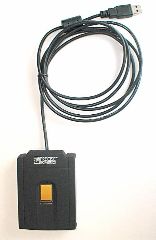
PBKMS010114
Jun 14, 2005Combined Finger Print and Smart Card Reader
Equipment Class
JBP - Part 15 Class B Computing Device Peripheral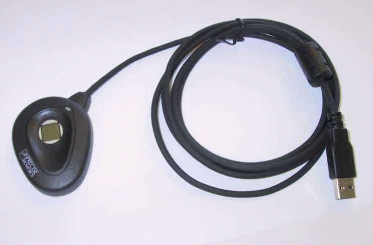
PBKMS010074
Jun 29, 2003Electronic Personnel Identification System
Equipment Class
JBP - Part 15 Class B Computing Device Peripheral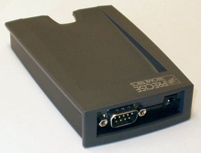
PBKMS010040
Mar 08, 2002Smart card
Equipment Class
DXX - Part 15 Low Power Communication Device Transmitter