PBLWL541MRouter with Wireless Card
Advance Multimedia Internet Technology Inc.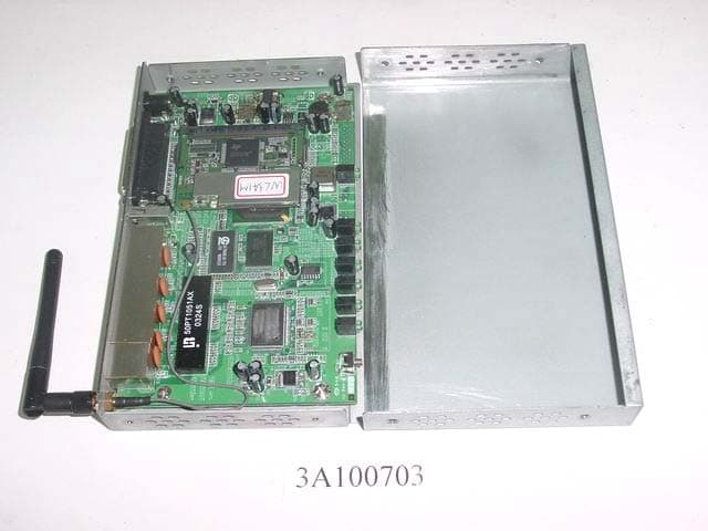
Click to zoom
Application Details
- Equipment Class
- DSS - Part 15 Spread Spectrum Transmitter
- Date of Grant
- Jan 05, 2004
- Application Purpose
- Original Equipment
- Date of Application
- Jan 05, 2004
- Equipment Note
- Router with Wireless Card
- Frequency Range
- 2412.00000000 - 2462.00000000
- Country
- Taiwan
Documents & Files
Document Text
Text extracted from the exhibit documents filed with the FCC. Open a document above to read the original.
Users Manual
User’s Manual Wireless ARM9 4port Full function version with VPN For internal reference only Charlie 20031002 Note: This page should be remove before send to Customer 1. This manual is modified base on 4-port wireless router, so some pictures are 4-port router, You may need to change them to fit your needs. Note: Watch out COM port, and Printer port, if this product doesn’t have them, you have to remove them. 2. Some functions are implemented on specific models only (the blue words) Charlie 20020807 4.add DHCP: gateway, Wireless: Pass-phrase Generator, Wizard: No ISP, MISC: Domain Filters, Ping Test, System Log: email alert, Syslog Charlie 20020918 5. UI is totally re-modified (change a lot). 6. Add Primary/secondary DNS, Primary/secondary WINS, Charlie 20020919 7. Add Primary setting: Virtual Computers, DHCP: Lease Time, Wireless: 802.1X Setting, System Time, VPN, Charlie 20021007 8. Add 802.11G, Appendix B XP/2000 IPSEC configuration 9. Correct Chapter 5 Printer Setup Charlie 20030526 10. Add RIPv1, RIPv2, SNMPv2, Log type, Email Alert – Username and Password, PPPOE –MTU, PPTP, L2TP Server, PPTP/L2TP pass through, URL Blocking, 20031002 Base on R1.94l3vTIG Note: Although this Manual is base on WQS4V7, but this version is not exactly for WQS4V7, this is a full function version (for all WQS4x7/ WQS4x8 series), so it has some features that Nobrand WQS4V7 doesn’t have. Please refer to your UI and remove those you don’t need. Copyright The contents of this publication may not be reproduced in any part or as a whole, stored, transcribed in an information retrieval system, translated into any language, or transmitted in any form or by any means, mechanical, magnetic, electronic, optical, photocopying, manual, or otherwise, without the prior written permission. Trademarks All product, company, brand names are trademarks or registered trademarks of their respective companies. They are used for identification purpose only. Specifications are subject to be changed without prior notice. FCC Interference Statement This equipment has been tested and found to comply with the limits for a Class B digital device, pursuant to Part 15 of the FCC Rules. These limits are designed to provide reasonable protection against harmful interference in a residential installation. This equipment generates, uses and can radiate radio frequency energy and, if not installed and used in accordance with the instructions, may cause harmful interference to radio communications. However, there is no guarantee that interference will not occur in a particular installation. If this equipment does cause harmful interference to radio or television reception, which can be determined by turning the equipment off and on, the user is encouraged to try to correct the interference by one or more of the following measures: -- Reorient or relocate the receiving antenna. -- Increase the separation between the equipment and receiver. -- Connect the equipment into an outlet on a circuit different from that to which the receiver is connected. -- Consult the dealer or an experienced radio/TV technician for help. CE Declaration of Conformity This equipment complies with the requirements relating to electromagnetic compatibility, EN 55022/A1 Class B, and EN 50082-1. This meets the essential protection requirements of the EuropeanCouncil Directive 89/336/EEC on the approximation of the laws of the member states relation to electromagnetic compatibility. Information to user. The users manual or instruction manual for an intentional or unintentional radiator shall caution the user that changes or modifications not expressly approved by the party responsible for compliance could void the user’s authority to operate the equipment. Table of Contents Chapter 1 Introduction .............................................................................. 7 Functions and Features ........................................................................ 7 Packing List ......................................................................................... 9 Chapter 2 Hardware Installation ............................................................... 9 2.1 Panel Layout (your product may need to be modified)................. 9 2.2 Procedure for Hardware Installation ............................................ 12 Chapter 3 Network Settings and Software Installation........................... 14 3.1 Make Correct Network Settings of Your Computer..................... 14 3.2 Install the Software into Your Computers (Optional).................. 14 Chapter 4 Configuring Wireless Broadband Router ............................... 18 4.1 Start-up and Log in ...................................................................... 18 4.2 Status............................................................................................ 19 4.3 Wizard .......................................................................................... 20 4.4 Basic Setting ................................................................................ 22 4.4.1 Primary Setup – WAN Type, Virtual Computers ...................... 23 4.4.2 DHCP Server............................................................................. 28 4.4.3 Wireless Setting, and 802.1X setting........................................ 30 4.4.4 Change Password ...................................................................... 32 4.5 Forwarding Rules......................................................................... 33 4.5.1 Virtual Server ............................................................................ 34 4.5.2 Special AP ................................................................................. 35 4.5.3 Miscellaneous Items.................................................................. 37 4.6 Security Settings .......................................................................... 38 4.6.1 Packet Filter ...........................................................................…
Text truncated - open the document above for the full version.
Users Manual
4.7 Advanced Setting 4.7.1 System Time Get Date and Time by NTP Protocol Selected if you want to Get Date and Time by NTP Protocol. Time Server Select a NTP time server to consult UTC time Time Zone Select a time zone where this device locates. Set Date and Time manually Selected if you want to Set Date and Time manually. Function of Buttons Sync Now: Synchronize system time with network time server 4.7.2 System Log IP Address for Syslog Host IP of destination where syslogs will be sent to. Check Enable to enable this function. E-mail Alert Enable Check if you want to enable Email alert(send syslog via email). SMTP Server IP and Port Input the SMTP server IP and port, which are concated with ':'. If you do not specify port number, the default value is 25. For example, "mail.your_url.com" or "192.168.1.100:26". Send E-mail alert to The recipients who will receive these logs. You can assign more than 1 recipient, using ';' or ',' to separate these email addresses. E-mail Subject The subject of email alert. This setting is optional. Username and Password To fill some SMTP server's authentication requirement, you may need to input Username and Password that offered by your ISP. Log type Please select the activities that should be shown on log. 4.7.3 Dynamic DNS To host your server on a changing IP address, you have to use dynamic domain name service (DDNS). So that anyone wishing to reach your host only needs to know the name of it. Dynamic DNS will map the name of your host to your current IP address, which changes each time you connect your Internet service provider. Before you enable Dynamic DNS, you need to register an account on one of these Dynamic DNS servers that we list in provider field. To enable Dynamic DNS click the check box next to Enable in the DDNS field. Next you can enter the appropriate information about your Dynamic DNS Server. You have to define: Provider Host Name Username/E-mail Password/Key You will get this information when you register an account on a Dynamic DNS server. Example: After Dynamic DNS setting is configured, click the save button. 4.7.4 SNMP Setting In brief, SNMP, the Simple Network Management Protocol, is a protocol designed to give a user the capability to remotely manage a computer network by polling and setting terminal values and monitoring network events. Enable SNMP You must check either Local or Remote or both to enable SNMP function. If Local is checked, this device will response request from LAN. If Remote is checked, this device will response request from WAN. Get Community Setting the community of GetRequest your device will response. Set Community Setting the community of SetRequest your device will accept. IP 1,IP 2,IP 3,IP 4 Input your SNMP Management PC’s IP here. User has to configure to where this device should send SNMP Trap message. SNMP Version Please select proper SNMP Version that your SNMP Management software supports Example: 1. This device will response to SNMP client which’s get community is set as “public” 2. This device will response to SNMP client which’s set community is set as “private” 3. This device will response request from both LAN and WAN 4. This device will send SNMP Trap message to 192.168.123.1 (Use SNMP Version V2c) 4.7.5 Routing Table Routing Tables allow you to determine which physical interface address to use for outgoing IP data grams. If you have more than one routers and subnets, you will need to enable routing table to allow packets to find proper routing path and allow different subnets to communicate with each other. Routing Table settings are settings used to setup the functions of static and dynamic routing. Dynamic Routing Routing Information Protocol (RIP) will exchange information about destinations for computing routes throughout the network. Please select RIPv2 only if you have different subnet in your network. Otherwise, please select RIPv1 if you need this protocol. Static Routing: For static routing, you can specify up to 8 routing rules. You can enter the destination IP address, subnet mask, gateway, hop for each routing rule, and then enable or disable the rule by checking or unchecking the Enable checkbox. Example: So if, for example, the host wanted to send an IP data gram to 192.168.3.88, it would use the above table to determine that it had to go via 192.168.1.33 (a gateway), And if it sends Packets to 192.168.5.77 will go via 192.168.1.55 Each rule can be enabled or disabled individually. After routing table setting is configured, click the save button. 4.7.5 Schedule Rule You can set the schedule time to decide which service will be turned on or off. Select the “enable” item. Press “Add New Rule” You can write a rule name and set which day and what time to schedule from “Start Time” to “End Time”. The following example configure “ftp time” as everyday 14:10 to 16:20 After configure Rule 1Æ Schedule Enable Selected if you want to Enable the Scheduler. Edit To edit the schedule rule. Delete To delete the schedule rule, and the rule# of the rules behind the deleted one will decrease one automatically. Schedule Rule can be apply to Virtual server and Packet Filter, for example: Exanple1: Virtual Server – Apply Rule#1 (ftp time: everyday 14:10 to 16:20) Exanple2: Packet Filter – Apply Rule#1 (ftp time: everyday 14:10 to 16:20). 4.8 Toolbox 4.8.1 System Log You can View system log by clicking the View Log button 4.8.2 Firmware Upgrade You can upgrade firmware by clicking Firmware Upgrade button. 4.8.3 Backup Setting You can backup your settings by clicking the Backup Setting button and save it as a bin file. Once you want to restore these settings, please click Firmware Upgrade button and use the bin file you saved. 4.8.4 Reset to default You can also reset this product to factory default by clicking the Reset to default button. 4.8.5 Reboot You can also reboot this product by clicking the Reboot button. 4.8.6 Miscellaneous Items MAC Address for Wake-on-LAN Wake-on-LAN is a technology that …
Text truncated - open the document above for the full version.
Users Manual
Charlie 20030401 Appendix B Win 2000/XP IPSEC Setting guide Example: Win XP/2000 ÆVPN Router (Configuration on WIN 2000 is similar to XP) 1. On Win 2000/XP, click [Start] button, select [Run], type secpol.msc in the field, then click [Run]Æ Goto **Local Security Policy Settings** page 2. Or in Win XP, Click [Control Pannel] Double-click [Performance and Maintenance] Double-click [Administrative Tools] Local Security Policy Settings Double-click [Local Security Policy] Right-click [IP Security Policies on Local Computer], and click [Create IP Security Policy]. Click the [Next] button, enter your policy’s name (Here it is to_vpn_router). Then, click [Next]. Introduction Dis-select the [Activate the default response rule] check box, and click [Next] button. Click [Finish] button, make sure [Edit] check box is checked. Build 2 Filter Lists: “xp->router” and “router->xp” Filter List 1: xp-> router In the “new policy’s properties” screen, disselect [Use Add Wizard] check box, and then click [Add] button to create a new rule. click [Add] button Enter a name, for example: xp->router and dis-select [Use Add Wizard] check box. Click [Add] button. In the Source address field, select [A specific IP Address]. and fill in IP Address: 192.168.1.1 In the Destination address field, select [A specific IP Subnet], fill in IP Address: 192.168.123.0 and Subnet mask: 255.255.255.0. If you want to select a protocol for your filter, click [Protocol] page. Click [OK] button. Then click [OK] button on the “IP Filter List” page. select [Filter Action], select [Require Security], then click [Edit] button. select [Negotiate security], Select [Session key Perfect Forward Secrecy (PFS)] click [Edit] button. select [Custom] button Select [Data integrity and encryption (ESP)] Configure “Integrity algorithm”: [MD5] Configure “Encryption algorithm”: [DES] Configure “Generate a new key every [10000] seconds” Click [OK] button select [Authentication Methods] page, click [Add] button. select [Use this string to protect the key exchange (preshared key)], and enter your preshared key string, such as mypresharedkey. Click [OK] button. Click [OK] button on [Authentication Methods] page. Select [Tunnel Setting] configure [The tunnel endpoint is specified by this IP address]: 192.168.1.254 Select [Connection Type] select [All network connections] Tunnel 2: router->xp In the “new policy’s properties” page, dis-select [Use Add Wizard] check box, and then click [Add] button to create a new rule. click [Add] button Enter a name, such as router->xp and dis-select [Use Add Wizard] check box. Click [Add] button. In the Source address field, select [A specific IP Subnet]. fill in IP Address: 192.168.123.0 and Subnet mask: 255.255.255.0. In the Destination address field, select [A specific IP Address], and fill in IP Address: 192.168.1.1 If you want to select a protocol for your filter, click [Protocol] page. Click [OK] button. Then click [OK] button on [IP Filter List] window. select [Filter Action tab], select [Require Security], then click [Edit] button. select [Negotiate security], Select [Session key Perfect Forward Secrecy (PFS)] click [Edit] button. select [Custom] button Select [Data integrity and encryption (ESP)] Configure “Integrity algorithm”: [MD5] Configure “Encryption algorithm”: [DES] Configure “Generate a new key every [10000] seconds” Click [OK] button select [Authentication Methods] page, click [Add] button. select [Use this string to protect the key exchange (preshared key)], and enter the preshared key string, such as mypresharedkey. Click [OK] button. Click [OK] button on [Authentication Methods] page. Select [Tunnel Setting] Configure [The tunnel endpoint is specified by this IP address]: 192.168.1.1 Select [Connection Type] select [All network connections] Configure IKE properties Select [General] Click [Advanced...] enable “Master key perfect forward security (PFS)” configure “Authenticate and generate a new key after every [10000] seconds” click [Methods...] click [Add] button Configure “Integrity algorithm”: [SHA1] Configure “Encryption algorithm”: [3DES] Configure “Diffie-Helman group”: [Medium (2)] Settings on VPN router VPN Router: Wan IP address:192.168.1.254 Lan IP address:192.168.123.254 PC: 192.168.123.123 VPN Settings: VPN: Enable Max. number of tunnels: 2 ID: 1 Tunnel Name: 1 Method: IKE Press “More”Æ VPN Settings - Tunnel 1 – IKE Tunnel:1 Local Subnet:192.168.123.0 Local Netmask:255.255.255.0 Remote Subnet:192.168.1.1 Remote Netmask:255.255.255.255 Remote Gateway:192.168.1.1 Preshare Key: mypresharedkey VPN Settings - Tunnel 1 - Set IKE Proposal ID: 1 Proposal Name: 1 DH Group: Group2 Encrypt. Algorithm: 3DES Auth. Algorithm: SHA1 Life Time: 10000 Life Time Unit: Sec. VPN Settings - Tunnel 1 - Set IPSec Proposal ID: 1 Proposal Name: proposal1 DH Group: Group2 Encap. Protocol: ESP Encrypt. Algorithm: DES Auth. Algorithm:MD5 Life Time: 10000 Life Time Unit: Sec. User can view VPN connection process in “System Log” page, and correct their settings. Phase1 is related to IKE settings, Phase2 is related to IPSEC settings. Appendix C Console Mode (optional) When you forget the system password or the IP address of this product, you need enter console mode to reset them. Before invoking the console program, be sure to find a null modem cable and use it to connect from this product’s COM port to your computer’s COM port. Then, execute a terminal program, such as the Hyper Terminal of MS Windows 95. The connection parameters should be set to 19200 8-N-1. And, reboot this product. When the M1 indicator starts flashing regularly, you can press the “Enter” key of the keyboard several times, there should be some messages and console prompt ">" appeared in the terminal. In the console mode, you may reset the IP address and the system password of this product. Please remember to execute the SR command to save the changes you have made. For example, IP 192.168.123.254 PW admin SR
Cover Letter(s)
Ersteller: U. Rodemeier Revision: 00 Erstelldatum: 3. August 2001 Datum: 3. August 2001 Seite 1 von 1 C:\Documents and Settings\jeff_c.IETC\桌面\amit fcc\文件\ApplicantLetter1 Agent Rev00.doc 永 洋 科 技 Advance Multimedia Internet Technology http://www.amit.com.tw TEL +886-6-2326201 FAX +886-6-2310211 PHOENIX TEST-LAB GmbH Product Certification Königswinkel 10 D 32825 Blomberg To Whom It May Concern: Please be advised that Advance Multimedia Internet Technology authorizes Interocean EMC Technology Corp .to act on our behalf, until otherwise notified, for applications submitted to PHOENIX TEST-LAB GmbH (PTL). We certify that we are not subject to denial of federal benefits, that includes FCC benefits, pursuant to Section 5301 of the Anti-Drug Abuse ACT of 1988, U.S.C.862. Further, no party, as defined in 47 CFR 1.2002 (b), to the application is subject to denial of federal benefits, that includes FCC benefits. Thank you for your attention to this matter. Signatory
Cover Letter(s)
= 永 洋 科 技 Advance Multimedia Internet Technology http://www.amit.com.tw TEL +886-6-2326201 FAX +886-6-2310211 DEC, 10, 2003 Federal Communications Commission Authorization and Evaluation Division FCC ID: PBLWL541M Confidentiality Request Pursuant to Sections 0.457 and 0.459 of the Commission’s Rules, the Applicant hereby requests confidential treatment of information accompanying this Application as outlined below: 1. Schematics 2. Operational Description 3. Block Diagram The above materials contain trade secrets and proprietary information not customarily released to the public. The public disclosure of these matters might be harmful to the Applicant and provide unjustified benefits to its competitors. The Applicant understands that pursuant to Rule 0.457, disclosure of this Application and all accompanying documentation will not be made before the date of the Grant for this application. Sincerely, Jason/Engineer Company Name: Advance Multimedia Internet Technology Inc (Singer Name) / (Title)
External Photos
Report No.: 3A100703FR FCC ID: PBLWL541M Page 52 of 59 Interocean EMC Technology Corp. FCC EMC Test Report 13 Photographs of EUT Front View of Appearance Rear View of Appearance Report No.: 3A100703FR FCC ID: PBLWL541M Page 53 of 59 Interocean EMC Technology Corp. FCC EMC Test Report I/O Port of EUT Inside view of EUT
Internal Photos
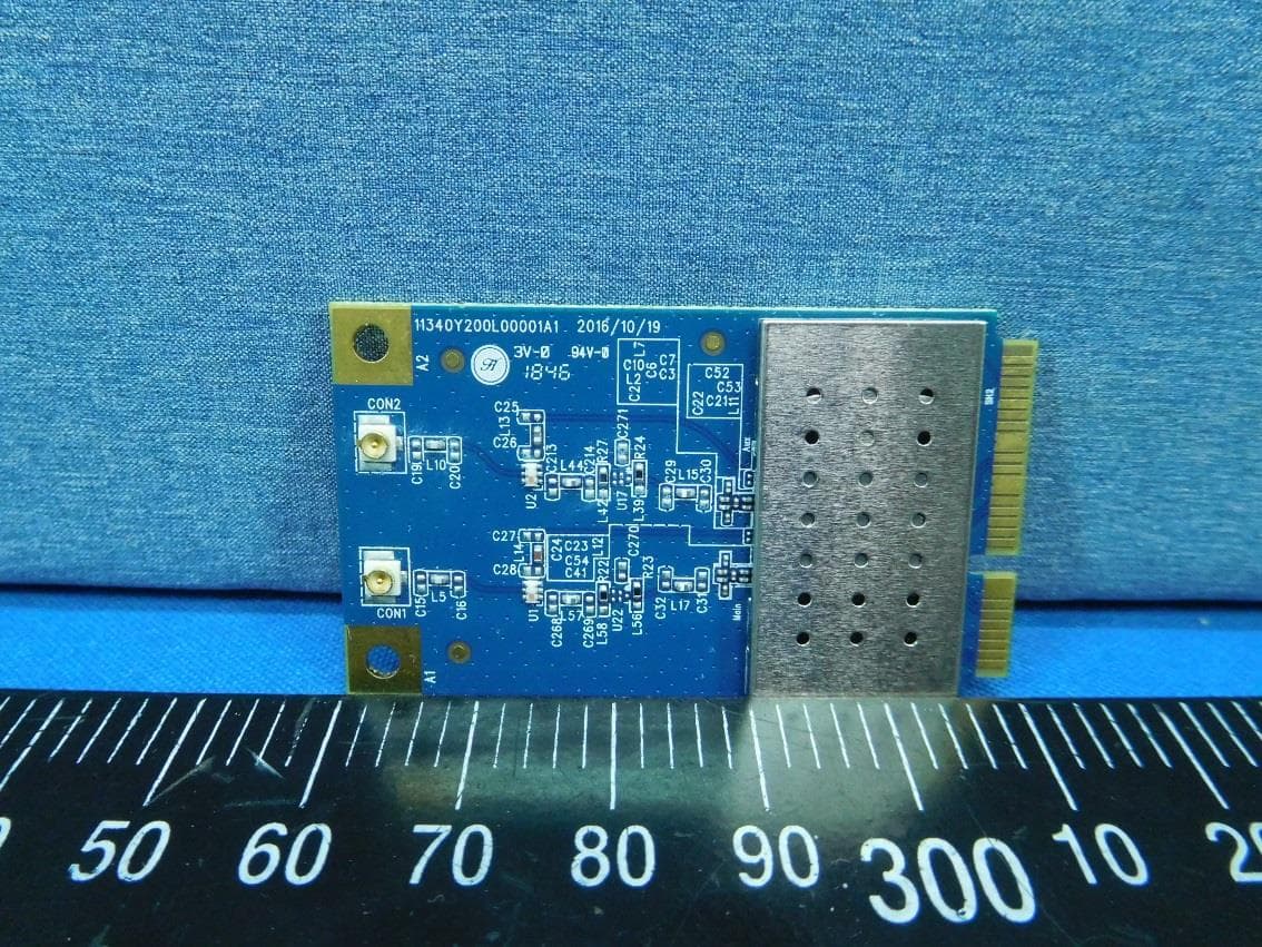
Report No.: 3A100703FR FCC ID: PBLWL541M Page 53 of 59 Interocean EMC Technology Corp. FCC EMC Test Report I/O Port of EUT Inside view of EUT Report No.: 3A100703FR FCC ID: PBLWL541M Page 54 of 59 Interocean EMC Technology Corp. FCC EMC Test Report Component view of Main Board Solder view of Main Board Report No.: 3A100703FR FCC ID: PBLWL541M Page 55 of 59 Interocean EMC Technology Corp. FCC EMC Test Report Component Side view of Wireless Card Component Side view of Wireless Card Report No.: 3A100703FR FCC ID: PBLWL541M Page 56 of 59 Interocean EMC Technology Corp. FCC EMC Test Report Solder Side view of Wireless Card Antenna Report No.: 3A100703FR FCC ID: PBLWL541M Page 57 of 59 Interocean EMC Technology Corp. FCC EMC Test Report Front View of Power Adapter Rear View of Power Adapter Report No.: 3A100703FR FCC ID: PBLWL541M Page 58 of 59 Interocean EMC Technology Corp. FCC EMC Test Report Inside View of Power Adapter Report No.: 3A100703FR FCC ID: PBLWL541M Page 59 of 59 Interocean EMC Technology Corp. FCC EMC Test Report Component Side of PCB (Power Adapter) Solder Side of PCB (Power Adapter)
RF Exposure Info
FCC TEST REPORT REPORT NO.: 3A100703 MODEL NO.: WQS418; WPS418; WUS418; WIS418 ACCORDING: FCC Guidelines for Human Exposure IEEE C95.1 APPLICANT: Advance Multimedia Internet Technology Inc ADDRESS: NO.32,Hwan-Gong Rd. Yung Kang City, Tainan Hsien, Taiwan , R.O.C ISSUED BY: Interocean EMC Technology Corp. LAB LOCATION: No.5-2, Lin 1, Tin-Fu Tsun, Lin-Kou Hsiang, Taipei County, Taiwan, R.O.C. RF Exposure Measurement (Fixed use Device) 1. Introduction 2.4GHz frequency band is regarded specially as a dangerous band for its heating harmfulness to the human body. That’s why microwave oven is operating in this frequency band. The manufacturer whose product is working in this frequency band is obligatory to prove the harmfulness of his product. In this document, we try to prove the safety of radiation harmfulness to the human body for our product. The limit for Maximum Permissible Exposure (MPE) specified in FCC 1.1310 is followed. The Gain of the antenna used in this product is measured in a Fully Anechoic Chamber (FAC), and the maximum total power input to the antenna is measured. Through the Friis transmission formula and the maximum gain of the antenna, we can calculate the distance, away from the product, where the limit of MPE is reached. 2. Classification The antenna of the product, under normal use condition, is at least 20cm away from the body of the user. Warning statement for keeping 20cm separation distance and the prohibition of operating next to a person has been printed on the user’s manual. So, this product is classified as the Fixed use Device 3. RF Exposure Limit According to FCC 1.1310: The criteria listed in the following table shall be used to evaluate the environmental impact of human exposure to radio-frequency (RF) radiation as specified in 1.1307(b). LIMITS FOR MAXIMUM PERMISSIBLE EXPOSURE (MPE) Frequency Range (MHz) Electric Field Strength (V/m) Magnetic Field Strength (A/m) Power Density (mW/cm 2 ) Average Time (minutes) (A) Limits For Occupational / Control Exposures 30-300 61.4 0.163 1.0 6 300-1500 ... ... F/300 6 1500-100,000 ... ... 5 6 (B)Limits For General Population / Uncontrolled Exposure 30-300 27.5 0.073 0.2 30 300-1500 ... ... F/500 30 1500-100,000 ... ... 1.0 30 F = Frequency in MHz 4. Friis Formula Friis transmission formula: Pd = (Pout*G) / (4*pi*r2) where Pd = power density in mW/cm2 Pout = output power to antenna in mW G = gain of antenna in linear scale Pi = 3.1416 R = distance between observation point and center of the radiator in cm Pd is the limit of MPE, 1 mW/cm2. If we know the maximum Gain of the antenna and the total power input to the antenna, through the calculation, we will know the distance r where the MPE limit is reached. 5. EUT Operating condition The software provided by Manufacturer enabled the EUT to transmit and receive data at lowest, middle and highest channel individually. 6. DESCRIPTION OF TEST MODES Operation mode Description of the EUT. 1 Router with Wireless Card WIS418/WL54M 7. Test Results 7.1 Antenna Gain The maximum Gain measured in Fully Anechoic Chamber is 2.0dBi or 1 (numeric). 7.2 Output Power Into Antenna & RF Exposure Distance: Mode 1 CHANNEL CHANNEL FREQUENCY (MHz) OUTPUT POWER TO ANTENNA (mW) MINIMUM ALLOWABLE DISTANCE ( r ) FROM SKIN (Centi-Meter) 1 2412 62.25 3.25 6 2437 51.60 2.89 11 2462 42.87 2.93 The minimum allowable distance is very close to the enclosure of the antenna. So, the user has no need to worry about the harmfulness of radiation. But it is recommended to always keep, at least, 20cm separation distance with the antenna.
Test Report
Report No.: 3A100703FR FCC ID: PBLWL541M Page 1 of 59 Interocean EMC Technology Corp. FCC EMC Test Report FCC Part 15 EMI TEST REPORT of E.U.T.:Router with Wireless Card Trade Name: N/A Model Number: WQS418; WPS418; WUS418; WIS418 Prepared for Prepared by Interocean EMC Technology Corp. No.5-2, Lin 1, Tin-Fu Tsun, Lin-Kou Hsiang, Taipei County, Taiwan, R.O.C. TEL.: +886 2 2600 6861 FAX.: +886 2 2600 6859 Remark: The test report consists of 59 pages in total. It shall not be reproduced except in full, without the written approval of IETC. This document may be altered or revised by IETC only, and shall be noted in the revision section of the document. The test results in the report only to the tested sample. Advance Multimedia Internet Technology Inc NO.32, Hwan-Gong Rd. Yung Kang City, Tainan Hsien, Taiwan , R.O.C TEL: +886 6 2326 223 FAX: +886 6 2310 211 Report No.: 3A100703FR FCC ID: PBLWL541M Page 3 of 59 Interocean EMC Technology Corp. FCC EMC Test Report Table of Contents 1 GENERAL INFORMATION 5 1.1 Description of Equipment Under Test 5 1.2 Details of Supporting System 7 1.3 Test Methodology 7 1.4 Test Facility 7 2 PROVISIONS APPLICABLE 8 2.1 Definition 8 2.2 Requirement for Compliance 9 2.3 Restricted Bands of Operation 11 2.4 Labeling Requirement 12 2.5 User Information 12 3 SYSTEM TEST CONFIGURATION 13 3.1 Justification 13 4 POWER LINE CONDUCTED EMISSION MEASUREMENT 14 4.1 Instrument 14 4.2 Block Diagram of Test Configuration 14 4.3 Conducted Limit (Power Line) 15 4.4 Measurement Procedure 15 4.5 Measuring Instrument 15 4.6 Test Step of EUT 15 5 RADIATED EMISSION MEASUREMENT 18 5.1 Instrument 18 5.2 Block Diagram of Test Configuration 18 5.3 Applicable Standard 19 5.4 Measurement Procedure 19 5.5 Measuring Instrument 20 5.6 Test Step of EUT 20 5.7 Radiated Emission Data 21 5.8 Field Strength Calculation 32 6 EMISSION LIMITATIONS – Conducted (Transmitter) 33 7 ANTENNA REQUIREMENT 34 7.1 Standard Applicable 34 7.2 Antenna Construction and Directional Gain 34 Report No.: 3A100703FR FCC ID: PBLWL541M Page 4 of 59 Interocean EMC Technology Corp. FCC EMC Test Report 8 EMISSION BANDWIDTH MEASUREMENT 35 8.1 Standard Applicable 35 8.2 Measurement Procedure 35 8.3 Measurement Equipment 35 8.4 Measurement Data 35 9 OUTPUT POWER MEASUREMENT 36 9.1 Standard Applicable 36 9.2 Measurement Procedure 36 9.3 Measurement Equipment 36 9.4 Measurement Data 36 10 100 kHz BANDWIDTH OF BAND EDGES MEASUREMENT 37 10.1 Standard Applicable 37 10.2 Measurement Procedure 37 10.3 Measurement Equipment 37 10.4 Measurement Data 37 11 POWER DENSITY MEASUREMENT 38 11.1 Standard Applicable 38 11.2 Measurement Procedure 38 11.3 Measurement Equipment 8.4 Measurement Data 38 11.4 Measurement Data 38 Appendix 1: POWER LINE CONDUCTED EMISSION MEASUREMENT 39 A1.1 Mode 1: Link Mode 39 Appendix 2: EMISSION BANDWIDTH MEASUREMENT 40 Appendix 3: OUTPUT POWER MEASUREMENT 42 Appendix 4: 100 kHz BANDWIDTH OF BAND EDGES MEASUREMENT 44 Appendix 5: POWER DENSITY MEASUREMENT 45 Appendix 6: EMISSION LIMITATIONS – Conducted (Transmitter) 47 12 Photographs of Measurement 50 12.1 Power Line Conducted Emission Measurement 50 12.2 Radiated Emission Measurement 51 13 Photographs of EUT 52 Report No.: 3A100703FR FCC ID: PBLWL541M Page 5 of 59 Interocean EMC Technology Corp. FCC EMC Test Report 1 GENERAL INFORMATION 1.1 Description of Equipment Under Test Equipment Under Test : Router with Wireless Card Model Number : WQS418; WPS418; WUS418; WIS418 Serial Number : N/A Type of Sample Tested : Proto-type Pre-Production Mass Production Applicant : Advance Multimedia Internet Technology Inc NO.32, Hwan-Gong Rd. Yung Kang City, Tainan Hsien, Taiwan, R.O.C Manufacturer : Advance Multimedia Internet Technology Inc NO.32, Hwan-Gong Rd. Yung Kang City, Tainan Hsien, Taiwan, R.O.C Power Adapter : AC Adapter Manufacturer: FAIRWAY, M/N: WN10B-050 Input: 100-240Vac, 50-60Hz, 1.0A Output: 5Vdc, 2.0A, 10W Power cable: Non-shielded Non-detachable, 1.8m Product information : Product Router with Wireless Card Rated RF Output Power 18dBm Type of Modulation BPSK/QPSK/CCK (DSSS) Antenna (Type) Dipole antenna Max.Gain 2.0dB Channel Spacing 5 MHz Number of channel 11 Bit rate of transmitter For IEEE802.11b (11Mbps). IEEE802.11g (54Mbps) Alignment range 2400 ~ 2483.5 MHz Operating frequency CH1(2412) ~ CH11(2462) MHz IF,L.O IF=374MHz,LO=2038~2088MHz Temperature range 0°C ~ +55°C Report No.: 3A100703FR FCC ID: PBLWL541M Page 6 of 59 Interocean EMC Technology Corp. FCC EMC Test Report Date of Receipt of Sample : Oct. 3, 2003 Date of Test : Oct. 3 ~ 9, 2002 Description of E.U.T. : 1. The Wireless Card (WL541M) was installed in to the router (WQS418) for testing. 2. The EUT is Router with Wireless Card. 3. Different specification of model numbers: Model Number USB Port Printer Port WQS418 ○ ○ WPS418 X ○ WUS418 ○ X WIS418 X X 4. The description of the connecting ports are as following: 1 LAN Port * 4. 2 WAN Port * 1. 3 Print Port * 1. 4 USB Port * 1. 5 DC Power Port * 1. 5. The WQS418 is representative selected in the test and included in this repor…
Text truncated - open the document above for the full version.
Contact Information
Applicant
Fred Lin(Engineer)
Technical Contact
Advance Multimedia Internet Technology Inc.Jason Tseng
[email protected]886 6 232 6223
No.32, Hwan-Gong Rd. Yung Kang City, · Tainan · Taiwan
Non-Technical Contact
Advance Multimedia Internet Technology Inc.Jason Tseng
[email protected]886 6 232 6223
Test Firm
Interocean EMC Technology Corp.Mike Huang
Technical Specifications
| # | Rule Parts | Frequency Range | Power Output |
|---|---|---|---|
| 1 | 15C | 2.41 GHz - 2.46 GHz | 62.23 mW |
Other Applications from Advance Multimedia Internet Technology Inc.
PBLMLC21AAM
Jan 29, 2020WiFi Module
Equipment Class
NII - Unlicensed National Information Infrastructure TX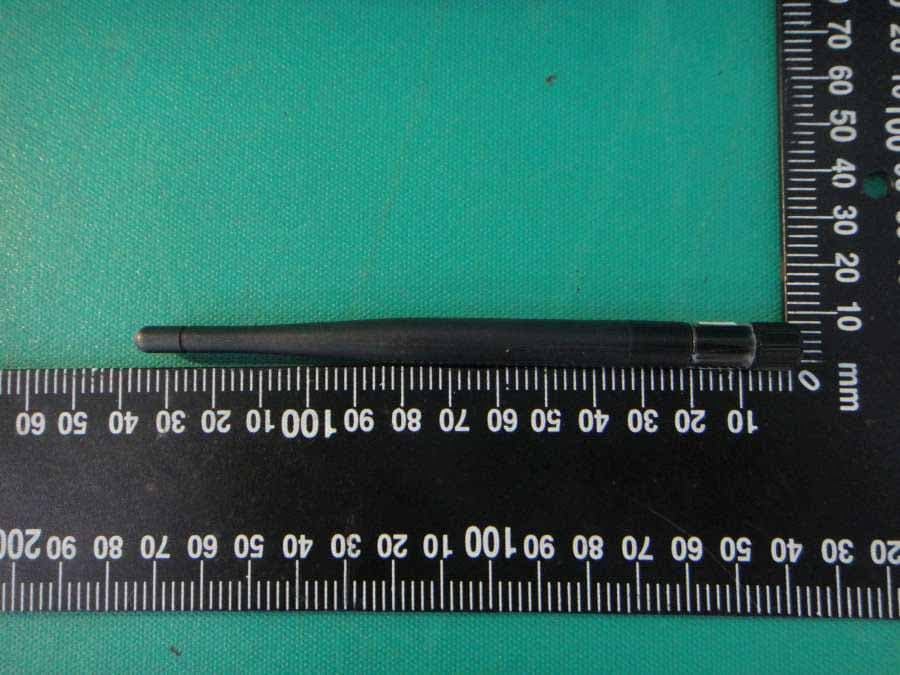
PBLCDD531AMU03
Apr 25, 2013WiFi ADSL2/2+ RG
Equipment Class
DTS - Digital Transmission System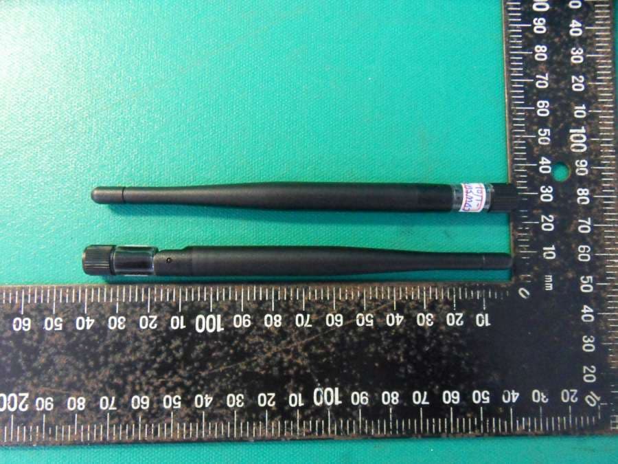
PBLCDE560AM001
Apr 18, 2013WiFi Combo Router / WiFi Broadband Router
Equipment Class
DTS - Digital Transmission System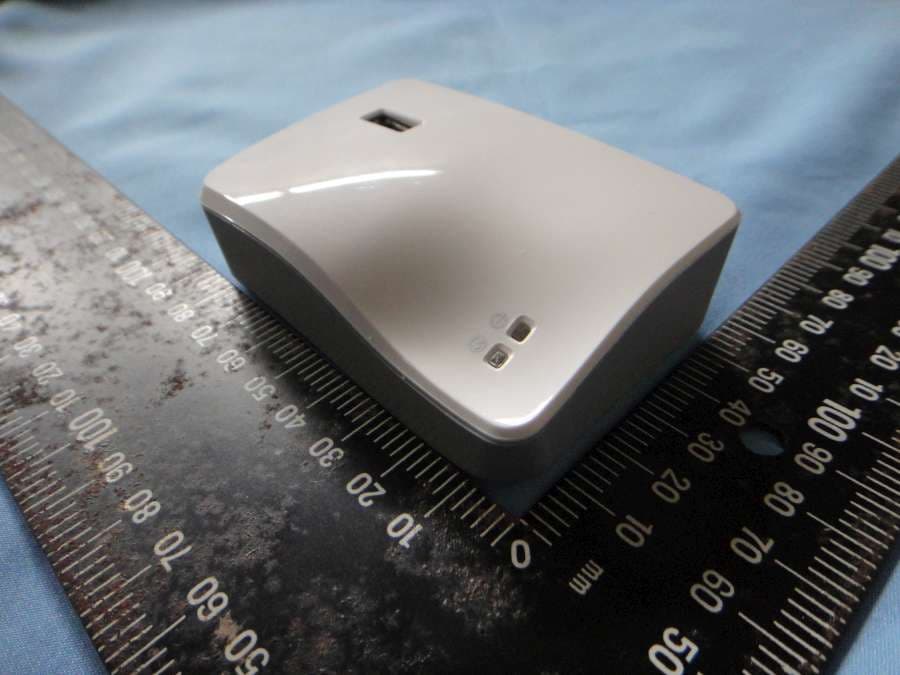
PBLCDM532AM001
Feb 05, 2013WiFi Mobile Router
Equipment Class
DTS - Digital Transmission System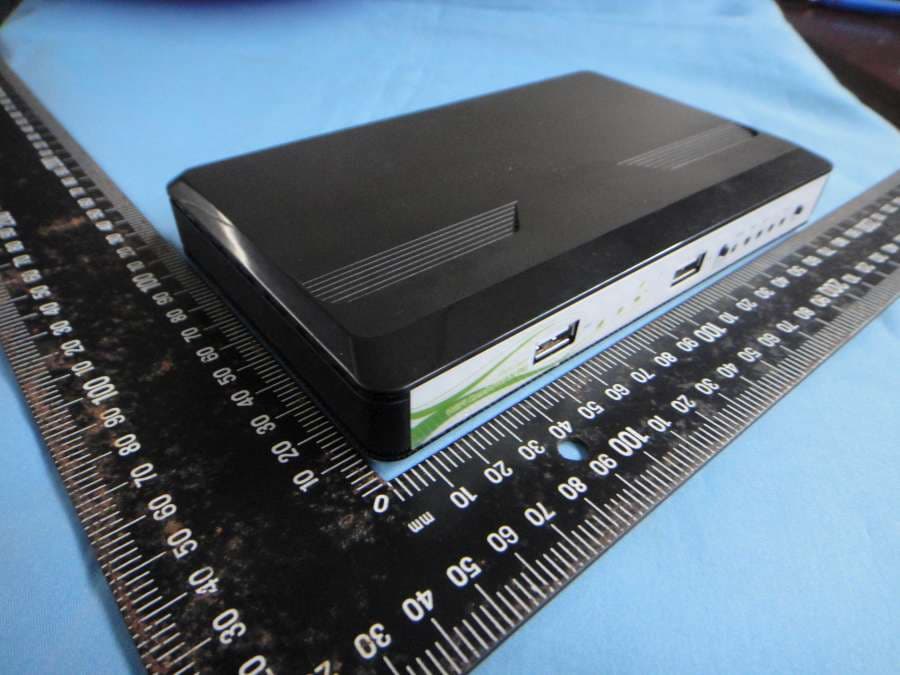
PBLCDW68AAMU01
Nov 01, 2012WiFi Broadband Router
Equipment Class
DTS - Digital Transmission System