PBLWL561MSIWireless Mini PCI Adapter
Advance Multimedia Internet Technology Inc.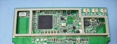
Click to zoom
Application Details
- Equipment Class
- DTS - Digital Transmission System
- Date of Grant
- Jun 06, 2006
- Application Purpose
- Original Equipment
- Date of Application
- Jun 06, 2006
- Equipment Note
- Wireless Mini PCI Adapter
- Frequency Range
- 2412.00000000 - 2462.00000000
- Country
- Taiwan
Documents & Files
Document Text
Text extracted from the exhibit documents filed with the FCC. Open a document above to read the original.
Users Manual
Wireless Mini PCI Adapter WL561MSI Manual FCC Information This device complies with Part 15 of the FCC Rules. Operation is subject to the following two conditions: 1. This device may not cause harmful interference. 2. This device must accept any interference received; including interference that may cause undesired operation. Federal Communications Commission (FCC) Statement. This Equipment has been tested and found to comply with the limits for a Class B digital device, pursuant to Part 15 of the FCC rules. These limits are designed to provide reasonable protection against harmful interference in a residential installation. This equipment generates uses and can radiate radio frequency energy and if not installed and used in accordance with the instructions, may cause harmful interference to radio communications. However, there is no guarantee that interference will not occur in a particular installation. If this equipment does cause harmful interference to radio or television reception, which can be determined by turning the equipment off and on, the user is encouraged to try to correct the interference by one or more of the following measures: - Reorient or relocate the receiving antenna. - Increase the separation between the equipment and receiver. - Connect the equipment into an outlet on a circuit different from that to which the receiver is connected. - Consult the dealer or an experienced radio/TV technician for help. FCC RF Radiation Exposure Statement: 1. This Transmitter must not be co-located or operating in conjunction with any other antenna or transmitter. 2. This equipment complies with FCC RF radiation exposure limits set forth for an uncontrolled environment. This equipment should be installed and operated with a minimum distance of 20 centimeters between the radiator and your body. IMPORTANT NOTE: In the event that these conditions can not be met (for example certain laptop configurations or co-location with another transmitter), then the FCC authorization is no longer considered valid and the FCC ID can not be used on the final product. In these circumstances, the OEM integrator will be responsible for re-evaluating the end product (including the transmitter) and obtaining a separate FCC authorization. End Product Labeling This transmitter module is authorized only for use in devices where the antenna may be installed such that 20 cm may be maintained between the antenna and users (for example access points, routers, wireless ADSL modems, and similar equipment). The final end product must be labeled in visible area with the following: “Contains TX FCC ID: PBLWL561MSI” End Product Manual Information The user manual for end users must include the following information in a prominent location “IMPORTANT NOTE: To comply with FCC RF exposure compliance requirements, the antenna used for this transmitter must be installed to provide a separation distance of at least 20cm from all persons and must not be co-located or operating in conjunction with any other antenna or transmitter.” Other important note: 1. The end user may not be provided with instructions to remove or install the device. 2. Changes or modifications not expressly approved by the party responsible for compliance could void the user's authority to operate the equipment. 3. This device is authorised for OEM integration only. Installation - Power down your computer. (for Mini PCI adapter, you don't need to do that) - Insert the wireless adapter into the Mini PCI slot for PCI adapter. - Power up your computer. - Select “Cancel” to ignore the “Found New Hardware Wizard” window after Windows been started up. - Insert the Product CD into the CD-ROM drive. - Execute “Setup.exe” in the root directory of the CD, it will guide you to install the Driver and Utility. - 2 - Management Load up utility After the installation, one utility will be run and minimized on Windows system tray bar. :Indicate wireless adapter detected, and connected to one site. :Indicated wireless adapter not detected, or not connected to one site. You may double click it to bring up the main menu. You may also use mouse right button to launch or to close it. For Windows XP, the utility provides one option to manage the wireless adapter with Windows Zero Configuration. Site Survey Page Under the site survey page, system will display the information of surrounding APs from last scan result. List information include SSID, BSSID, Signal, Channel, Encryption algorithm, and Network type. Definition of each field - SSID: Name of BSS of IBSS network. - BSSID: MAC address of AP or randomly generated of IBSS. - Signal: Receive signal strength of specified network. - Channel: Channel in use. - Encryption: Encryption algorithm used within than BSS or IBSS. Valid value includes WEP, TKIP, AES, and Not Use. - Authentication: Authentication mode used within the network, including Unknown, WPA-PSK, WPA2-PSK, WPA and WPA2. - Network Type: Network type in use, Infrastructure for BSS, Ad-Hoc for IBSS network. Connected network When utility first ran, it will select the best AP to connect automatically. It is available to connect to other site by double click the intended item. If the intended network has encryption other than '' Not Use '' or “Unknown”, the security page will pop up for you to setup the appropriate information to make the connection. - 3 - : This icon indicates the change is successful. - Connection box: Indicate connection status, the connected network SSID will show up here. - Rescan: Issue an rescan command to wireless NIC to update information on surrounding wireless network. - Connect: Command to connect to the selected network. - Add to Profile: Add the selected AP to profile setting. It will bring up profile page and save the setting to a new profile. Add/Edit Profile System Configuration - Profile Name: User chose name for this profile. - SSID: User can key in the intended SSID name or use pull down menu to select from available APs. - Power Sa…
Text truncated - open the document above for the full version.
Attestation Statements
Advance Multimedia Internet Technology Inc. No. 32, Hwan-Gong Rd. Yung Kang City, Tainan Hsien, Taiwan Attestation FCC ID PBLWL561MSI Product Wireless Mini PCI Adapter Model WL561MSI Statements: We don’t provide with any controls or software to allow operation outside the USA frequency band for all future applications when we sell this product in USA. Sincerely, Signature:
Cover Letter(s)
Transmitter Modular Approval Letter Date: June 01, 2006 Federal Communications Commission Re: Application Modular Approval Certification for FCC ID: PBLWL561MSI Gentlemen: The following attestation addresses the eight requirements to support Modular approval as required by the FCC Public Notice DA 00-1407” Part 15 Unlicensed Modular Transmitter Approval” 1 The modular transmitter has its own RF shielding.(Refer to “Internal Photograph Exhibit”) 2 The modular transmitter has buffered modulation/data inputs. All inputs to the modules are buffered through the radio circuitry. (Refer to “Block Diagram and Schematics Exhibit”) 3 The modular transmitter has its own power supply regulator.(Refer to “Block Diagram and Schematics Exhibit ”and Bill of Materials Exhibit”) 4 The modular transmitter has an antenna that complies with section 15.203 of the FCC rules. It has a UFL type of connector at the transmitter end and is Printed to the antenna (depending on OEM configuration). Also the antenna will be internal in the OEM host equipment and inaccessible to the user.(Refer to “Operational Description Exhibit” and “Antenna Specification Exhibit”) 5 The modular transmitter was tested outside of a host desktop computer using a PCI extender card. The PCI extender card allows the transmitter to be placed outside of the chassis of the host desktop computer.(Refer to “Test Configuration”in Compliance Certificaiton Services Inc. test report and to “External Photograph Exhibit”) 6 The modular transmitter will be labeled with it own FCC ID. Also, the OEM host computer manufacturer will be informed to display a label referring to the enclosed module. The exterior habel will read as follows: “Contains Transmitter Module FCC ID: PBLWL561MSI” or “Contains TX FCCID: PBLWL561MSI” (Refer to “Label Information Exhibit”) 7 The modular transmitter is manufactured so that the user cannot influence the operation of the transmitter that will operate outside of the scope of the regulations.(Refer to“User’s Guide Exhibit) 8 The modular transmitter meets the MPE calculations of 47 CFR 1.1307(b)(1) (Refer to “RF Exposure Exhibit”.)
Cover Letter(s)
Advance Multimedia Internet Technology Inc. No. 32, Hwan-Gong Rd. Yung Kang City, Tainan Hsien, Taiwan Confidentiality Request FCC ID : PBLWL561MSI Product : Wireless Mini PCI Adapter Model : WL561MSI Pursuant to Sections 0.457 and 0.459 of the Commission’s Rules, the Applicant hereby requests confidential treatment of information accompanying this Application as outlined below: Schematics Block Diagram Operational Description The above materials contain trade secrets and proprietary information not customarily released to the public. The public disclosure of these matters might be harmful to the Applicant and provide unjustified benefits to its competitors. The Applicant understands that pursuant to Rule 0.457, disclosure of this Application and all accompanying documentation will not be made before the date of the Grant for this application. Sincerely yours,
External Photos
Compliance Certification Services Inc.Report No.60321401-RP1 External Photo ( Model : WL561MSI)
ID Label/Location Info
Company : Advance Multimedia Internet Technology Inc. Model : WL561MSI Product :Wireless Mini PCI Adapter Label Here Wireless Mini PCI Adapter Model No: WL561MSI FCC ID:PBLWL561MSI This device complies with part 15 of the FCC Rules. Operation is subject to the following two conditions: [1] this device may not cause harmful interference and [2] this device must accept any interference received, including interference that may cause undesired operation. S/N: Made in Taiwan
Internal Photos
Compliance Certification Services Inc.Report No.60321401-RP1 External Photo ( Model : WL561MSI) Compliance Certification Services Inc.Report No.60321401-RP1
RF Exposure Info
Compliance Certification Services Inc. Report No: 60321401-RP1 FCC ID: PBLWL561MSI Date of Issue: May 16, 2006 Page 33 7.5 RADIO FREQUENCY EXPOSURE LIMIT Systems operating under the provisions of this section shall be operated in a manner that ensures that the public is not exposed to radio frequency energy levels in excess of the Commission's guidelines. See §15.247(i) and §1.1307(b)(1) of this chapter. EUT Specification EUT Wireless Mini PCI Adapter Frequency band (Operating) WLAN: 2.412GHz ~ 2.462GHz WLAN: 5.18GHz ~ 5.32GHz / 5.50GHz ~ 5.70GHz WLAN: 5.745GHz ~ 5.825GHz Others Device category Portable (<20cm separation) Mobile (>20cm separation) Others Exposure classification Occupational/Controlled exposure (S = 5mW/cm2) General Population/Uncontrolled exposure (S=1mW/cm2) Antenna diversity Single antenna Multiple antennas Tx diversity Rx diversity Tx/Rx diversity Max. output power 21.28dBm (134.28mW) Antenna gain (Max) 1.8 dBi (Numeric gain: 1.513561) Evaluation applied MPE Evaluation SAR Evaluation Remark: 1. The maximum output power is 21.28(134.28mW) at 2437MHz (with 1.513561 numeric antenna gain.) 2. DTS device is not subject to routine RF evaluation; MPE estimate is used to justify the compliance. 3. For mobile or fixed location transmitters, no SAR consideration applied. The minimum separation generally be used is at least 20 cm, even if the calculations indicate that the MPE distance would be lesser. TEST RESULTS No non-compliance noted. Compliance Certification Services Inc. Report No: 60321401-RP1 FCC ID: PBLWL561MSI Date of Issue: May 16, 2006 Page 34 Calculation Given d GP E ×× = 30 & 3770 2 E S= Where E = Field Strength in Volts / meter P = Power in Watts G=Numeric antenna gain d=Distance in meters S=Power Density in milliwatts / square centimeter Combining equations and re-arranging the terms to express the distance as a function of the remaining variables yields: S GP d × ×× = 3770 30 Changing to units of mW and cm, using: P (mW) = P (W) / 1000 and d (cm) =100 * d (m) Yields S GP S GP d × ×= × ×× ×=282.0 3770 )1000/(30 100 Where d = distance in cm P = Power in mW G = Numeric antenna gain S = Power Density in mW / cm^2 Substituting the logarithmic form of power and gain using: P (mW) = 10 ^ (P (dBm) / 10) and G (numeric) = 10 ^ (G (dBi) / 10) Yields 20 10 282.0 20 )(GP d + ×= Equation 1 Where d = MPE safe distance in cm P = Power in dBm G = Antenna Gain in dBi S = Power Density Limit in mW / cm^2 Compliance Certification Services Inc. Report No: 60321401-RP1 FCC ID: PBLWL561MSI Date of Issue: May 16, 2006 Page 35 Maximum Permissible Exposure (2.4 GHz Band) EUT output power = 134.28mW Antenna Gain = 1.513561(Numeric gain) S = 1.0 mW / cm^2 from 1.1310 Table 1 Substituting these parameters into the above Equation 1: ‡ MPE Safe Distance =4.059381cm (For mobile or fixed location transmitters, the minimum separation distance is 20 cm, even if calculations indicate that the MPE distance would be less.)
Test Report
Compliance Certification Services Inc. Report No: 60321401-RP1 FCC ID: PBLWL561MSI Date of Issue: May 16, 2006 Note: This report shall not be reproduced except in full, without the written approval of Compliance Certification Services Inc. This document may be altered or revised by Compliance Certification Services Inc. personnel only, and shall be noted in the revision section of the document. Total Page: 74 Page 1 FCC 47 CFR PART 15 SUBPART C TEST REPORT For Wireless Mini PCI Adapter Model Number: WL561MSI Issued to Advance Multimedia Internet Technology Inc. No. 32, Hwan-Gong Rd. Yung Kang City, Tainan Hsien, Taiwan Issued by Compliance Certification Services Inc. Ta i n a n L a b . No. 8, Jiu Cheng Ling, Jiaokeng Village,Sinhua Township, Tainan Hsien 712, Taiwan R.O.C. TEL: 886-6-580-2201 FAX: 886-6-580-2202 Compliance Certification Services Inc. Report No: 60321401-RP1 FCC ID: PBLWL561MSI Date of Issue: May 16, 2006 Page 2 TABLE OF CONTENTS 1 TEST RESULT CERTIFICATION....................................................................................................3 2 EUT DESCRIPTION ...........................................................................................................................4 3 TEST METHODOLOGY ....................................................................................................................5 3.1 EUT CONFIGURATION.......................................................................................................................5 3.2 EUT EXERCISE..................................................................................................................................5 3.3 GENERAL TEST PROCEDURES............................................................................................................5 3.4 FCC PART 15.205 RESTRICTED BANDS OF OPERATIONS .......................................................6 3.5 DESCRIPTION OF TEST MODES...........................................................................................................7 4 INSTRUMENT CALIBRATION........................................................................................................7 5 FACILITIES AND ACCREDITATIONS ..........................................................................................8 5.1 FACILITIES.........................................................................................................................................8 5.2 EQUIPMENT.......................................................................................................................................8 5.3 LABORATORY ACCREDITATIONS AND LISTING.................................................................................8 5.4 TABLE OF ACCREDITATIONS AND LISTINGS......................................................................................9 6 SETUP OF EQUIPMENT UNDER TEST .......................................................................................10 6.1 SETUP CONFIGURATION OF EUT......................................................................................................10 6.2 SUPPORT EQUIPMENT ...............................................................................................................10 7 FCC PART 15.247 REQUIREMENTS.............................................................................................11 7.1 6DB BANDWIDTH ........................................................................................................................11 7.2 PEAK POWER...................................................................................................................................17 7.3 BAND EDGES MEASUREMENT ................................................................................................23 7.4 PEAK POWER SPECTRAL DENSITY...................................................................................................33 7.5 RADIO FREQUENCY EXPOSURE........................................................................................................39 7.6 SPURIOUS EMISSIONS ...............................................................................................................42 7.7 POWER LINE CONDUCTED EMISSIONS.............................................................................................69 8 APPENDIX 1 PHOTOGRAPHS OF TEST SETUP .......................................................................72 Compliance Certification Services Inc. Report No: 60321401-RP1 FCC ID: PBLWL561MSI Date of Issue: May 16, 2006 Page 3 1 TEST RESULT CERTIFICATION Applicant Advance Multimedia Internet Technology Inc. Address No. 32, Hwan-Gong Rd. Yung Kang City, Tainan Hsien, Taiwan Manufacture Advance Multimedia Internet Technology Inc. Address No. 32, Hwan-Gong Rd. Yung Kang City, Tainan Hsien, Taiwan Equipment Under Test Wireless Mini PCI Adapter Model Number WL561MSI Date of Test April 25, 2006 ~ May 04, 2006 APPLICABLE STANDARDS STANDARD TEST RESULT FCC 47 CFR Part 15 Subpart C No non-compliance noted We hereby certify that: The above equipment was tested by Compliance Certification Services Inc. The test data, data evaluation, test procedures, and equipment configurations shown in this report were made in accordance with the procedures given in ANSI C63.4 and the energy emitted by the sample EUT tested as described in this report is in compliance with the requirements of FCC Rules Part 15.207, 15.209, 15.247. The test results of this report relate only to the tested sample EUT identified in this report. Approved by: Reviewed by: May 16, 2006 May 16, 2006 Alex Chiu Jeter Wu Manager Section Manager Compliance Certification Services Inc. Compliance Certification Services Inc. Compliance Certification Services Inc. Report No: 60321401-RP1 FCC ID: PBLWL561MSI Date of Issue: May 16, 2006 Page 4 2 EUT DESCRIPTION Product Wireless Mini PCI Adapter Model Number WL561MSI Model Discrepancy N/A Power Supply Powered from Note Book Frequency Range 2412 ~ 2462 MHz Tr…
Text truncated - open the document above for the full version.
Test Setup Photos
Compliance Certification Services Inc. Report No: 60321401-RP1 FCC ID: PBLWL561MSI Date of Issue: May 16, 2006 Page 64 8 APPENDIX 1 PHOTOGRAPHS OF TEST SETUP Radiated Emission Set up Photos Compliance Certification Services Inc. Report No: 60321401-RP1 FCC ID: PBLWL561MSI Date of Issue: May 16, 2006 Page 65 Compliance Certification Services Inc. Report No: 60321401-RP1 FCC ID: PBLWL561MSI Date of Issue: May 16, 2006 Page 66 Conducted Emission Set Up Photos End of report
Contact Information
Applicant
Fred Lin(Engineer)
Test Firm
Compliance Certification Service Inc.Paul Liau
Technical Specifications
| # | Rule Parts | Frequency Range | Power Output |
|---|---|---|---|
| 2 | 15C | 2.41 GHz - 2.46 GHz | 94.80 mW |
Other Applications from Advance Multimedia Internet Technology Inc.
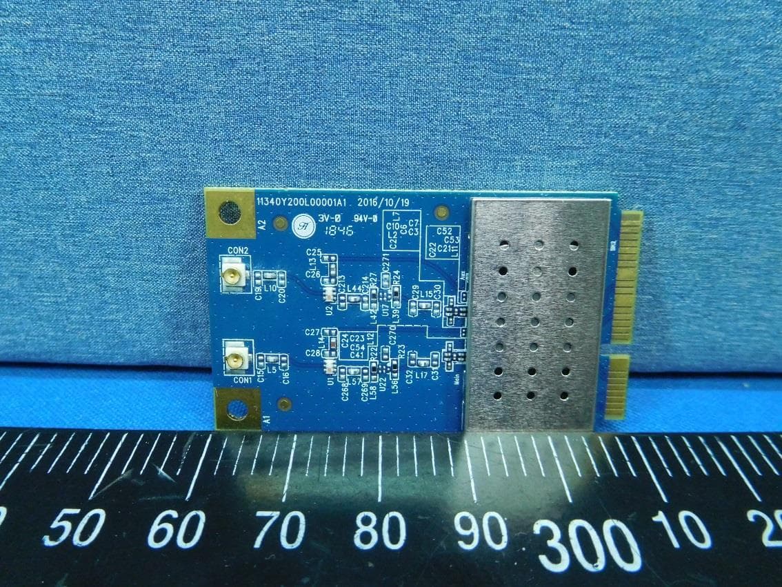
PBLMLC21AAM
Jan 29, 2020WiFi Module
Equipment Class
NII - Unlicensed National Information Infrastructure TX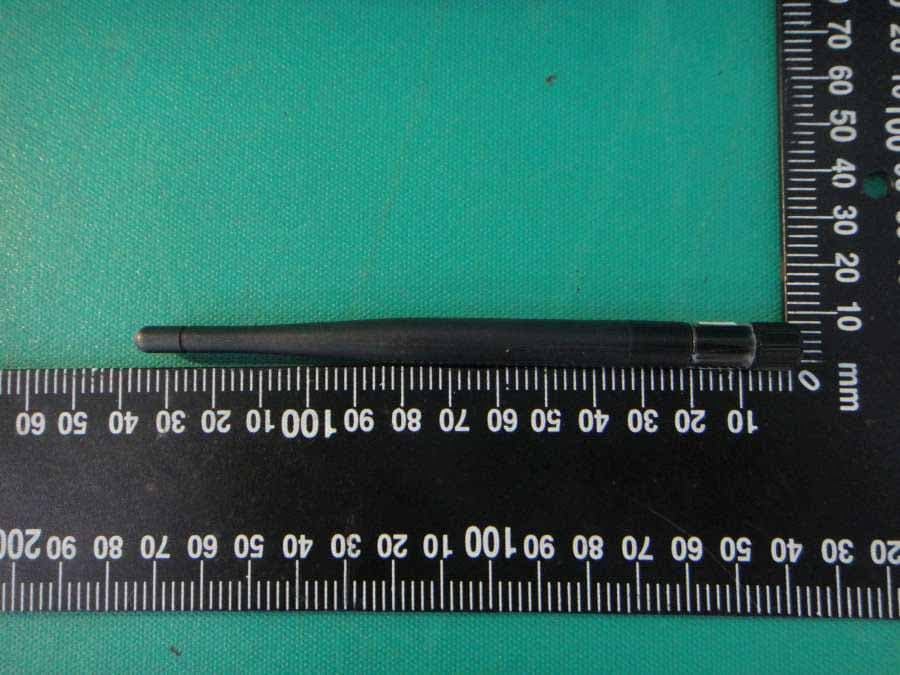
PBLCDD531AMU03
Apr 25, 2013WiFi ADSL2/2+ RG
Equipment Class
DTS - Digital Transmission System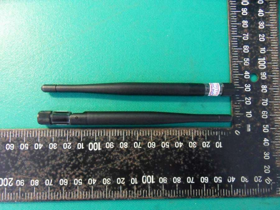
PBLCDE560AM001
Apr 18, 2013WiFi Combo Router / WiFi Broadband Router
Equipment Class
DTS - Digital Transmission System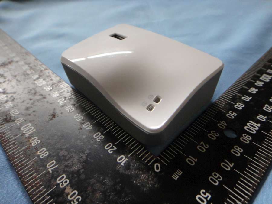
PBLCDM532AM001
Feb 05, 2013WiFi Mobile Router
Equipment Class
DTS - Digital Transmission System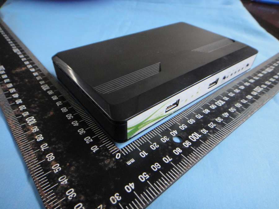
PBLCDW68AAMU01
Nov 01, 2012WiFi Broadband Router
Equipment Class
DTS - Digital Transmission System