PBLWL561PAMPCI Adapter
Advance Multimedia Internet Technology Inc.
Click to zoom
Application Details
- Equipment Class
- DTS - Digital Transmission System
- Date of Grant
- Jan 24, 2006
- Application Purpose
- Original Equipment
- Date of Application
- Jan 24, 2006
- Equipment Note
- PCI Adapter
- Frequency Range
- 2412.00000000 - 2462.00000000
- Country
- Taiwan
Documents & Files
Document Text
Text extracted from the exhibit documents filed with the FCC. Open a document above to read the original.
Users Manual
CardBus / PCI Adapter 11G WIRELESS Network Adapter User’s Manual Production component This WIRELESS production should contain the following items: 1. One piece of CardBus or PCI adapter 11G WIRELESS LAN Card 2. One piece of CD which contain drivers, user’s manual, and utility Quick Installation 1. Insert the product’s CD into CD-ROM. 2. Exit all application programs and insert the 11G WIRELESS adapter into the PCMCIA on notebook or PCI slot on desktop. 3. Following “Found New Hardware Wizard” window to install driver step by step. 4. Install the WIRELESS adapter utility 5. Configure your WIRELESS adapter for connecting to a WIRELESS network. FCC Information This device complies with Part 15 of the FCC Rules. Operation is subject to the following two conditions: 1. this device may not cause harmful interference, and 2. this device must accept any interference received; including interference that may cause undesired operation. Federal Communications Commission (FCC) Statement. This Equipment has been tested and found to comply with the limits for a Class B digital device, pursuant to Part 15 of the FCC rules. These limits are designed to provide reasonable protection against harmful interference in a residential installation. This equipment generates, uses and can radiate radio frequency energy and, if not installed and used in accordance with the instructions, may cause harmful interference to radio communications. However, there is no guarantee that interference will not occur in a particular installation. If this equipment does cause harmful interference to radio or television reception, which can be determined by turning the equipment off and on, the user is encouraged to try to correct the interference by one or more of the following measures: - Reorient or relocate the receiving antenna. - Increase the separation between the equipment and receiver. - Connect the equipment into an outlet on a circuit different from that to which the receiver is connected. - i - - Consult the dealer or an experienced radio/TV technician for help. FCC RF Radiation Exposure Statement: 1. This Transmitter must not be co-located or operating in conjunction with any other antenna or transmitter. 2. This equipment complies with FCC RF radiation exposure limits set forth for an uncontrolled environment. This equipment should be installed and operated with a minimum distance of 20 centimeters between the radiator and your body. - ii - Contents CHAPTER 1 TERMINOLOGY INTRODUCTION......................................................................1 CHAPTER 2 SYSTEM REQUIREMENTS....................................................................................3 2-1 HARDWARE....................................................................................................................................3 2-2 SOFTWARE.....................................................................................................................................3 CHAPTER 3 INSTALL DRIVER FOR WINDOWS SERIES ......................................................4 3-1 SET UP WIRELESS LAN CARD FOR WINDOWS XP...................................................................4 3-2 SET UP WIRELESS LAN CARD FOR WINDOWS 2000................................................................7 3-3 SET UP WIRELESS LAN CARD FOR WINDOWS 98/ ME.........................................................11 3-4 UNINSTALL THE WIRELESS LAN CARD.................................................................................14 CHAPTER 4 CONFIGURE THE WIRELESS LAN ADAPTER...............................................17 4-1 INSTALL UTILITY........................................................................................................................17 4-2 CONFIGURE WIRELESS LAN ADAPTER FOR WINDOWS XP...................................................18 4-3 CONFIGURE WIRELESS LAN ADAPTER FOR WINDOWS 98/ME/2000 BY UTILITY...............21 - iii - Chapter 1 Terminology Introduction This chapter will introduce terminology about IEEE802.11 what referred by this manual. And in this character we will explain terminology according to IEEE802.11 Std. z Ad-Hoc Network(Peer to Peer) A network composed solely of stations within mutual communication range of each other via the WIRELESS medium(WM). An Ad Hoc network is typically created in a spontaneous manner. The principal distinguishing characteristic of an ad hoc network is limited temporal and spatial extent. These limitations allow the act of creating and dissolving the ad hoc network to be sufficiently straightforward and convenient so as to be achievable by nontechnical users of the network facilities; i.e., no specialized “technical skills” are required and little or no investment of time or additional resources is required beyond the stations that are to participate in the ad hoc network. The term ad hoc is often used as slang to refer to an independent basic service set(IBSS). z Infrastructure Network The infrastructure includes the distribution system medium (DSM), access point(AP), and portal entities. It is also the logical location of distribution and integration service functions of an extended service set(ESS). An infrastructure contains one or more APs and zero or more portals in addition to the distribution system(DS). z Basic Service Set(BSS) A set of stations controlled by a single coordination function. z BSSID Basic service set identifier z Station service(SS) The set of services that support transport of medium access control(MAC) service data units(MSDUs) between stations within a basic service set(BSS) z SSID Station service identifier - 1 - z Association The service used to establish access point/station(AP/STA) mapping and enable STA invocation of the distribution system services(DSSs). z Authentication The service used to establish the identify of one station as a member of the set of stations authorized to associate with another station. z Channel an instance of medium use for …
Text truncated - open the document above for the full version.
Attestation Statements
Advance Multimedia Internet Technology Inc. NO.32, Hwan-Gong Rd. Yung Kang City,Tainan Hsien, Taiwan. Attestation FCC ID : PBLWL561PAM Product : PCI Adapter Model : WL561PAM Statements: We don’t provide with any controls or software to allow operation outside the USA frequency band for all future applications when we sell this product in USA. Sincerely, Signature: (Name / Date)
External Photos
Compliance Certification Services Inc.Report No.51207401-RP1 H External Photo ( Model : WL561PAM )
ID Label/Location Info
Company : Advance Multimedia Internet Technology Inc. Model : WL561PAM Product : PCI Adapter PCI Adapter Model No: WL561PAM FCC IDPBLWL561PAM This device complies with part 15 of the FCC Rules. Operation is subject to the following two conditions: [1] this device may not cause harmful interference and [2] this device must accept any interference received, including interference that may cause undesired operation. S/N Made in Taiwan Label Here
Internal Photos
Compliance Certification Services Inc.Report No.51207401-RP1 H Antenna Compliance Certification Services Inc.Report No.51207401-RP1 H Internal Photo
RF Exposure Info
Compliance Certification Services Inc. Report No: 51207401-RP1 FCC ID: PBLWL561PAM Date of Issue: January 16, 2006 Page 33 RADIO FREQUENCY EXPOSURE LIMIT Systems operating under the provisions of this section shall be operated in a manner that ensures that the public is not exposed to radio frequency energy levels in excess of the Commission's guidelines. See §15.247(i) and §1.1307(b)(1) of this chapter. EUT Specification EUT PCI Adapter Frequency band (Operating) WLAN: 2.412GHz ~ 2.462GHz WLAN: 5.18GHz ~ 5.32GHz / 5.50GHz ~ 5.70GHz WLAN: 5.745GHz ~ 5.825GHz Others Device category Portable (<20cm separation) Mobile (>20cm separation) Others Exposure classification Occupational/Controlled exposure (S = 5mW/cm2) General Population/Uncontrolled exposure (S=1mW/cm2) Antenna diversity Single antenna Multiple antennas Tx diversity Rx diversity Tx/Rx diversity Max. output power 25.41dBm (347.54mW) Antenna gain (Max) 1.8 dBi (Numeric gain: 1.5136) Evaluation applied MPE Evaluation SAR Evaluation Remark: 1. The maximum output power is 25.41 dBm (347.54 mW) at 2437MHz (with 1.5136 numeric antenna gain.) 2. DTS device is not subject to routine RF evaluation; MPE estimate is used to justify the compliance. 3. For mobile or fixed location transmitters, no SAR consideration applied. The minimum separation generally be used is at least 20 cm, even if the calculations indicate that the MPE distance would be lesser. TEST RESULTS No non-compliance noted. Compliance Certification Services Inc. Report No: 51207401-RP1 FCC ID: PBLWL561PAM Date of Issue: January 16, 2006 Page 34 Calculation Given d GP E ×× = 30 & 3770 2 E S = Where E = Field Strength in Volts / meter P = Power in Watts G=Numeric antenna gain d=Distance in meters S=Power Density in milliwatts / square centimeter Combining equations and re-arranging the terms to express the distance as a function of the remaining variables yields: S GP d × ×× = 3770 30 Changing to units of mW and cm, using: P (mW) = P (W) / 1000 and d (cm) =100 * d (m) Yields S GP S GP d × ×= × ×× ×= 282.0 3770 )1000/(30 100 Where d = distance in cm P = Power in mW G = Numeric antenna gain S = Power Density in mW / cm^2 Substituting the logarithmic form of power and gain using: P (mW) = 10 ^ (P (dBm) / 10) and G (numeric) = 10 ^ (G (dBi) / 10) Yields 20 10 282.0 20 )(GP d + ×= Equation 1 Where d = MPE safe distance in cm P = Power in dBm G = Antenna Gain in dBi S = Power Density Limit in mW / cm^2 Compliance Certification Services Inc. Report No: 51207401-RP1 FCC ID: PBLWL561PAM Date of Issue: January 16, 2006 Page 35 Maximum Permissible Exposure (2.4 GHz Band) EUT output power = 347.5362 mW Antenna Gain = 1.5136 (Numeric gain) S = 1.0 mW / cm^2 from 1.1310 Table 1 Substituting these parameters into the above Equation 1: Æ MPE Safe Distance =6.5307 cm (For mobile or fixed location transmitters, the minimum separation distance is 20 cm, even if calculations indicate that the MPE distance would be less.)
Test Report
Compliance Certification Services Inc. Report No: 51207401-RP1 FCC ID: PBLWL561PAM Date of Issue: January 16, 2006 Note: This report shall not be reproduced except in full, without the written approval of Compliance Certification Services Inc. This document may be altered or revised by Compliance Certification Services Inc. personnel only, and shall be noted in the revision section of the document. Page 1 FCC 47 CFR PART 15 SUBPART C TEST REPORT For PCI Adapter Model Number: WL561PAM Brand Name: AMIT Issued to Advance Multimedia Internet Technology Inc. No. 32, Hwan-Gong Rd. Yung Kang City, Tainan Hsien, Taiwan Issued by Compliance Certification Services Inc. Ta i n a n L a b . No. 8, Jiu Ceng Ling, Jiaokeng Village,Sinhua Township, Tainan Hsien 712, Taiwan R.O.C. TEL: 886-6-580-2201 FAX: 886-6-580-2202 Compliance Certification Services Inc. Report No: 51207401-RP1 FCC ID: PBLWL561PAM Date of Issue: January 16, 2006 Page 2 TABLE OF CONTENTS 1 TEST RESULT CERTIFICATION....................................................................................................3 2 EUT DESCRIPTION ...........................................................................................................................4 3 TEST METHODOLOGY ....................................................................................................................5 3.1 EUT CONFIGURATION.......................................................................................................................5 3.2 EUT EXERCISE..................................................................................................................................5 3.3 GENERAL TEST PROCEDURES............................................................................................................5 3.4 FCC PART 15.205 RESTRICTED BANDS OF OPERATIONS .......................................................6 3.5 DESCRIPTION OF TEST MODES...........................................................................................................7 4 INSTRUMENT CALIBRATION........................................................................................................7 5 FACILITIES AND ACCREDITATIONS ..........................................................................................8 5.1 FACILITIES.........................................................................................................................................8 5.2 EQUIPMENT.......................................................................................................................................8 5.3 LABORATORY ACCREDITATIONS AND LISTING.................................................................................8 5.4 TABLE OF ACCREDITATIONS AND LISTINGS......................................................................................9 6 SETUP OF EQUIPMENT UNDER TEST .......................................................................................10 6.1 SETUP CONFIGURATION OF EUT......................................................................................................10 6.2 SUPPORT EQUIPMENT ...............................................................................................................10 7 FCC PART 15.247 REQUIREMENTS.............................................................................................11 7.1 6DB BANDWIDTH ........................................................................................................................11 7.2 PEAK POWER...................................................................................................................................15 7.3 BAND EDGES MEASUREMENT ................................................................................................19 7.4 PEAK POWER SPECTRAL DENSITY...................................................................................................29 7.5 RADIO FREQUENCY EXPOSURE........................................................................................................33 7.6 SPURIOUS EMISSIONS ...............................................................................................................36 7.7 POWER LINE CONDUCTED EMISSIONS.............................................................................................61 8 APPENDIX 1 PHOTOGRAPHS OF TEST SETUP .......................................................................64 Compliance Certification Services Inc. Report No: 51207401-RP1 FCC ID: PBLWL561PAM Date of Issue: January 16, 2006 Page 3 1 TEST RESULT CERTIFICATION Applicant Advance Multimedia Internet Technology Inc. Address NO. 32, Hwan-Gong Rd. Yung Kang City, Tainan Hsien, Taiwan Equipment Under Test PCI Adapter Model Number WL561PAM Brand Name AMIT Date of Test January 04, 2006 ~ January 09, 2006 APPLICABLE STANDARDS STANDARD TEST RESULT FCC 47 CFR Part 15 Subpart C No non-compliance noted We hereby certify that: The above equipment was tested by Compliance Certification Services Inc. The test data, data evaluation, test procedures, and equipment configurations shown in this report were made in accordance with the procedures given in ANSI C63.4 and the energy emitted by the sample EUT tested as described in this report is in compliance with the requirements of FCC Rules Part 15.207, 15.209, 15.247. The test results of this report relate only to the tested sample EUT identified in this report. Approved by: Reviewed by: Jan. 16, 2006 Jan. 16, 2006 Alex Chiu Jeter Wu Manager Section Manager Compliance Certification Services Inc. Compliance Certification Services Inc. Compliance Certification Services Inc. Report No: 51207401-RP1 FCC ID: PBLWL561PAM Date of Issue: January 16, 2006 Page 4 2 EUT DESCRIPTION Product PCI Adapter Model Number WL561PAM Brand Name AMIT Model Discrepancy N/A Power Supply Powered from PC DC 3.3V Frequency Range 2412 ~ 2462 MHz Transmit Power IEEE802.11b mode: 25.41 dBm IEEE802.11g mode: 23.80 dBm Modulation Technique IEEE802.11b: DSSS…
Text truncated - open the document above for the full version.
Test Setup Photos
Compliance Certification Services Inc. Report No: 51207401-RP1 FCC ID: PBLWL561PAM Date of Issue: January 16, 2006 Page 64 8 APPENDIX 1 PHOTOGRAPHS OF TEST SETUP Radiated Emission Set up Photos Compliance Certification Services Inc. Report No: 51207401-RP1 FCC ID: PBLWL561PAM Date of Issue: January 16, 2006 Page 65 Conducted Emission Set Up Photos Compliance Certification Services Inc. Report No: 51207401-RP1 FCC ID: PBLWL561PAM Date of Issue: January 16, 2006 Page 66
Contact Information
Applicant
Fred Lin(Engineer)
Test Firm
Compliance Certification Service Inc.Paul Liau
Technical Specifications
| # | Rule Parts | Frequency Range | Power Output |
|---|---|---|---|
| 1 | 15C | 2.41 GHz - 2.46 GHz | 347.50 mW |
Other Applications from Advance Multimedia Internet Technology Inc.
PBLMLC21AAM
Jan 29, 2020WiFi Module
Equipment Class
NII - Unlicensed National Information Infrastructure TX
PBLCDD531AMU03
Apr 25, 2013WiFi ADSL2/2+ RG
Equipment Class
DTS - Digital Transmission System
PBLCDE560AM001
Apr 18, 2013WiFi Combo Router / WiFi Broadband Router
Equipment Class
DTS - Digital Transmission System
PBLCDM532AM001
Feb 05, 2013WiFi Mobile Router
Equipment Class
DTS - Digital Transmission System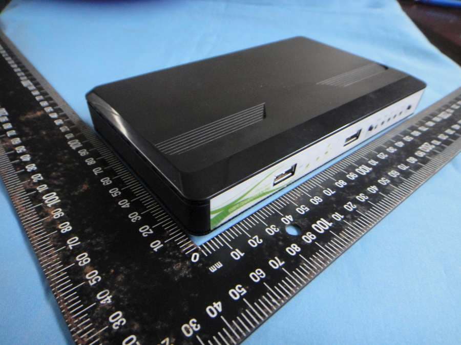
PBLCDW68AAMU01
Nov 01, 2012WiFi Broadband Router
Equipment Class
DTS - Digital Transmission System