PEY1150APBluetooth Access Point
Red-M (Communications) Limited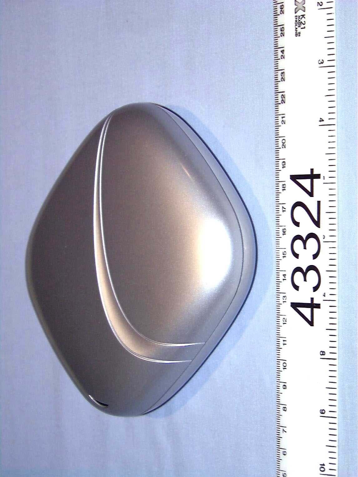
Click to zoom
Application Details
- Equipment Class
- DSS - Part 15 Spread Spectrum Transmitter
- Date of Grant
- Jun 01, 2002
- Application Purpose
- Original Equipment
- Date of Application
- Jun 01, 2002
- Equipment Note
- Bluetooth Access Point
- Frequency Range
- 2402.00000000 - 2480.00000000
- Country
- United Kingdom
Documents & Files
Document Text
Text extracted from the exhibit documents filed with the FCC. Open a document above to read the original.
Users Manual
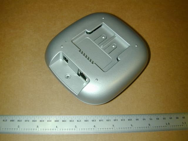
Red-M 1000AP access point getting started guide 980-957-05 Red-M 1000AP getting started guide 2 Before starting, read the License and Warranty agreement included in the packaging as this becomes legally binding on you as soon as you install or use this product. Trademarks: Red-M, the Red-M logo, and Genos are trademarks, and in some jurisdictions may be registered trademarks, of Red-M (Communications) Ltd. Bluetooth is a trademark owned by Bluetooth SIG Inc USA and used by Red-M under license. Other trademarks appearing in this document are the property of their respective owners. Copyright © 2002 Red-M. All Rights Reserved. Red-M 1000AP getting started guide 3 Ta b l e o f c o n t e n t s Introduction ................................................. 5 Mounting the 1000AP..................................... 7 Connecting the cables .................................... 9 Using more complicated networks ..................12 Connecting power ........................................12 Configuring 1000APs.....................................13 Using Identify mode .....................................14 Reading the LED ..........................................15 1000AP diagram ..........................................16 Contact information ......................................17 Regulatory information..................................17 Red-M 1000AP getting started guide 4 Red-M 1000AP getting started guide 5 Introduction Red-M™ 1000AP™ access points are designed to work with Genos™ software, which runs on the Red-M 3000AS™ access server or a Linux server. 1000AP access points enhance your Bluetooth™ infrastructure by letting more users connect over a wider area. 1000APs have a Bluetooth range of up to 100 meters (for high-powered devices) or around 15 meters (for low-powered devices). Range often varies with both the connecting device and the surrounding environment. Installation There are two installation options: ‘star-wiring’ or ‘daisy-chaining’. Connect 1000APs to your LAN using Category 5 Ethernet cables with standard RJ-45 connectors. There should be no more than 100 meters of cabling between two 1000APs or between a 1000AP and the Ethernet port to which it is connected. This is an Ethernet limitation. For more information about cabling, see Connecting the cables on page 9. Note: When configuring a 1000AP on your management PC, this guide refers to Genos software version 2.0 and above. If you have BIAS version 1.3 or earlier installed on your 3000AS, upgrade to the latest version of Genos available from the Red-M website (www.red-m.com). Note: Some jurisdictions require special wiring if installing cables into a ceiling cavity. They may also have special conditions about installing products on a ceiling or installing the supplied power adapter. If in doubt, contact your local authority. Red-M 1000AP getting started guide 6 Before you start Before you start, you need: •Either a configured Red-M 3000AS access server or a Linux server with Genos installed •Category 5 Ethernet cables with RJ-45 connectors •The DC 12v power adapter (included) •If mounting on a ceiling or wall: -Two screws -A mounting bracket (included) -A screwdriver •An Ethernet hub or switch (if installing in a ‘star-wire’ configuration). Note: The mounting bracket may already be fitted to the 1000AP during packaging. You may want to remove the bracket to use the 1000AP on a desktop. Note: If you use the star-wire configuration from the Access Point port of a 3000AS, and connect to a switch or hub’s standard ports, you will need an Ethernet crossover cable. Red-M 1000AP getting started guide 7 Mounting the 1000AP The 1000AP has a mounting bracket that can be attached to a ceiling or wall using appropriate screws and suitable fastenings. We recommend mounting on a ceiling, since 1000APs provide superior Bluetooth coverage in a horizontal position. Each 1000AP must be connected to its supplied power adapter, so take this into account when mounting in a wall cavity or ceiling. For optimum Bluetooth performance, install the 1000AP(s) in direct line-of-sight with the devices that will use the 1000AP (ideally not behind wall partitions or around corners). Figure 1: Mounting the 1000AP to a ceiling or wall Red-M 1000AP getting started guide 8 To mount on a ceiling or wall: 1.Select a location on a ceiling or wall to mount the 1000AP (we recommend mounting on a ceiling). 2.Ensure the ceiling or wall can support the 1000AP’s weight (around 250 g or 8.5 oz). If in doubt, consult a licensed installer. 3.Install the Category 5 Ethernet cable according to whether you decided to ‘star-wire’ or ‘daisy-chain’ the 1000AP’s cabling (see Connecting the cables on page 9). Ensure these and the power cable emerge at the correct point (see Figure 1 on page 7). 4.Use the mounting bracket as a template to mark out drill positions. 5.Drill two holes (43 mm apart) using a 5.5 mm drill bit. Ensure the two holes are vertically aligned if mounting on a wall. The holes must be 75 mm from the cabling hole in the wall or ceiling to ensure a flush fitting (60 mm from the mounting bracket’s edge). 6.Insert suitable fastenings into the holes (e.g. wall plugs). 7.Position the mounting bracket over the two holes and insert the appropriate screws. 8.Connect the cables from the hole in the ceiling/wall to the 1000AP. 9.Slide the 1000AP over the mounting bracket until it fits into the groove. Continue sliding until it locks into place. Red-M 1000AP getting started guide 9 Connecting the cables Cabling depends on whether you decide to ‘star-wire’ or ‘daisy-chain’ the 1000AP(s), and to which Genos server you connect. You must use the power adapter provided to connect power to each 1000AP. Star-wiring from a 3000AS Star-wiring means using an Ethernet switch or hub to connect 1000APs to the Genos server as shown in Figure 2 below. Star-wiring is recommended if you plan to install more than two 1000APs. Star-wiring uses the 1000AP’s IN port to connect the cable fr…
Text truncated - open the document above for the full version.
Block Diagram
16 16 P1 P0 SERIAL CPU FLASH 1MByte CSR BC2 XILINX UART SDRAM 8MByte FLASH 2MByte PSU & CTRL PCM Ethernet ports LNA PA Filter
External Photos
Radio Frequency Investigation Ltd, Ewhurst Park, Ramsdell, Basingstoke, Hampshire, RG26 5RQ, ENGLAND. Tel: +44 (0) 1256 851193 Fax: +44 (0) 1256 851192 Registered in England, No. 211 7901. Registered Office: Ewhurst Park, Ramsdell, Basingstoke, Hampshire RG26 5RQ TESTING 0644 PHOTOGRAPH SECTION - EXTERNAL FOR RFI TEST REPORT SERIAL NO: RFI/EMCB3/RP43324B Test Of: Red-M (Communications) Ltd. PEY1150AP Access Point To: F.C.C. Part 15 Subpart C: 2000 (Intentional Radiators) Section 15.247 RADIO FREQUENCY INVESTIGATION LTD.Photograph Section - External S.No: RFI/EMCB3/RP43324B EMC Department Test Of:Red-M (Communications) Ltd. PEY1150AP Access Point To:F.C.C. Part 15 Subpart C: 2000 (Intentional Radiators) Section 15.247 This section contains the following photographs: Photo Reference NumberTitle PHT/43324B/001Overall View of EUT PHT/43324B/002Front View of EUT PHT/43324B/003Rear View of EUT These pages are not included in the total number of pages for this report. RADIO FREQUENCY INVESTIGATION LTD.Photograph Section - External S.No: RFI/EMCB3/RP43324B EMC Department Test Of:Red-M (Communications) Ltd. PEY1150AP Access Point To:F.C.C. Part 15 Subpart C: 2000 (Intentional Radiators) Section 15.247 PHT/43324B/001 Overall View of EUT RADIO FREQUENCY INVESTIGATION LTD.Photograph Section - External S.No: RFI/EMCB3/RP43324B EMC Department Test Of:Red-M (Communications) Ltd. PEY1150AP Access Point To:F.C.C. Part 15 Subpart C: 2000 (Intentional Radiators) Section 15.247 PHT/43324B/002 Front View of EUT RADIO FREQUENCY INVESTIGATION LTD.Photograph Section - External S.No: RFI/EMCB3/RP43324B EMC Department Test Of:Red-M (Communications) Ltd. PEY1150AP Access Point To:F.C.C. Part 15 Subpart C: 2000 (Intentional Radiators) Section 15.247 PHT/43324B/003 Rear View of EUT
ID Label/Location Info
ARTWORK All detail within this box to be printed except that shown in RED. Any detail in GREEN to be printed but see notes for specific content. Notes: (1) Serial Numbers increment in steps of 4, with right-hand character being either 2, 6, A or E. Specific range of values will be specified with order. (2) Artwork to be made from CorelDraw (.CDR) format. PDF format for inspection only. (3) Barcode is format Code39 and comprises a 2-Character Prefix as defined above followed by the right-hand 6 characters of “Serial No. / Bluetooth Address” (eg “ZZDDDDDE” where “ZZ” is the 2-Character Prefix). Artwork - Red-M 1000AP Access Point, Rating Plate Label LAD-VE - CE + US/Can/CSA + BT Mark 158-272-01 158-131-01 Artwork Revision A RevDateBy 1/5/02NE TITLE: USE BLANK STOCK: VERSION: ARTWORK/LABEL PART NUMBER: Copyright 20021 Red-M© Serial Number / Bluetooth Address: 000281 DDDDDE Assembly: 158-245-01 Made in Ireland 1 5 8 - 2 7 2 - 0 1 © Red-M 2002. Patents Pending FCC ID: PEY1150APCanada 3868 1150AP 1000AP Access Point Barcode 2-Character Prefix is “ZR” “Made in Ireland” version Initial Release of LAD-VE version Red-M Neptune House Mercury Park Wycombe Lane Wooburn Green Bucks HP10 0HH England
ID Label/Location Info
ARTWORK All detail within this box to be printed except that shown in RED. Any detail in GREEN to be printed but see notes for specific content. Notes: (1) Serial Numbers increment in steps of 4, with right-hand character being either 2, 6, A or E. Specific range of values will be specified with order. (2) Artwork to be made from CorelDraw (.CDR) format. PDF format for inspection only. (3) Barcode is format Code39 and comprises a 2-Character Prefix as defined above followed by the right-hand 6 characters of “Serial No. / Bluetooth Address” (eg “ZZDDDDDE” where “ZZ” is the 2-Character Prefix). Artwork - Red-M 1050AP LAN Access Point, Rating Plate Label 158-276-01 158-131-01 Artwork Revision A RevDateBy 1/5/02NE TITLE: USE BLANK STOCK: VERSION: ARTWORK/LABEL PART NUMBER: Copyright 2002 Red-M© Serial Number / Bluetooth Address: 000281 DDDDDE Assembly: 158-275-01 Made in Ireland 1 5 8 - 2 7 6 - 0 1 © Red-M 2002. Patents Pending FCC ID: PEY1150APCanada 3868 1150AP 1050AP LAN Access Point Barcode 2-Character Prefix is “ZQ” “Made in Ireland” version Red-M Neptune House Mercury Park Wycombe Lane Wooburn Green Bucks HP10 0HH England LAD-VE - CE + US/Can/CSA + BT Mark Initial Release of LAD-VE version
Internal Photos
Integral antenna.
Operational Description
Bluetooth radio and baseband operation: a summary Bluetooth operates using frequency hopping spread spectrum techniques (FHSS) with Gaussian frequency shift keying (GFSK). The parameters of these techniques are described in more detail below. For more information please refer to the Radio and Baseband specification chapters of the Bluetooth Core specification at http://www.bluetooth.com/developer/specification/Bluetooth_11_Specifications_Book.pdf Bluetooth channel definition The Bluetooth channel is represented by a pseudo-random hopping sequence hopping through 79 RF channels. The hopping sequence is unique for each piconet (a group of units comprising a master and up to 7 slaves all sharing the same channel) and is determined by the Bluetooth device address of the master; the phase in the hopping sequence is determined by the Bluetooth clock of the master. The channel is divided into time slots where each slot corresponds to an RF hop frequency. Consecutive hops correspond to different RF hop frequencies. The nominal hop rate is 1600 hops/s. All Bluetooth units participating in the piconet are time- and hop- synchronized to the channel. Time slots The channel is divided into time slots, each 625 ms in length. The time slots are numbered according to the Bluetooth clock of the piconet master. The slot numbering ranges from 0 to 2 27 -1 and is cyclic with a cycle length of 2 27 . In the time slots, master and slave can transmit packets. A time division duplex scheme is used where master and slave alternatively transmit. The master shall start its transmission in even-numbered time slots only, and the slave shall start its transmission in odd-numbered time slots only. The packet start shall be aligned with the slot start. Packets transmitted by the master or the slave may extend over up to five time slots. The RF hop frequency shall remain fixed for the duration of the packet. For a single packet, the RF hop frequency to be used is derived from the current Bluetooth clock value. For a multi-slot packet, the RF hop frequency to be used for the entire packet is derived from the Bluetooth clock value in the first slot of the packet. The RF hop frequency in the first slot after a multi-slot packet shall use the frequency as determined by the current Bluetooth clock value. If a packet occupies more than one time slot, the hop frequency applied shall be the hop frequency as applied in the time slot where the packet transmission was started. Modulation and bit rate The data transmitted has a symbol rate of 1 Ms/s. A Gaussian-shaped, binary FSK modulation is applied with a BT product of 0.5. A binary one is represented by a positive frequency deviation, a binary zero by a negative frequency deviation. The maximum frequency deviation shall be between 140 kHz and 175 kHz. Modulation and characteristics The Modulation is GFSK (Gaussian Frequency Shift Keying) with a BT=0.5. The Modulation index must be between 0.28 and 0.35. A binary one is represented by a positive frequency deviation, and a binary zero is represented by a negative frequency deviation. The symbol timing shall be better than ±20 ppm. For each transmit channel, the minimum frequency deviation (Fmin = the lesser of {Fmin+, Fmin-}) which corresponds to 1010 sequence shall be no smaller than ±80% of the frequency deviation (fd) which corresponds to a 00001111 sequence. In addition, the minimum deviation shall never be smaller than 115 kHz. The zero crossing error is the time difference between the ideal symbol period and the measured crossing time. This shall be less than ± 1/8 of a symbol period.
Operational Description
BLUETOOTH APPROVALS. The following exhibit indicates the FCC Spread Spectrum requirements in Section 15.247 for devices meeting the Bluetooth Specifications in the 2.4 GHz band as of Feb 2001 operating in the USA. The purpose of this exhibit is to help expedite the approval process for Bluetooth devices. This exhibit provides items that are common to all Bluetooth devices. The list of common items can be submitted for each application for equipment authorization. Items Common to all Bluetooth Devices. 1. Output power and channel separation of a Bluetooth device in the different operating modes. The different operating modes (data-mode, acquisition-mode) of a Bluetooth device don’t influence the output power and the channel spacing. There is only one transmitter, which is driven by identical input parameters concerning these parameters. Only a different hopping sequence will be used. For this reason the RF parameters in one-op mode is sufficient. 2. Frequency range of a Bluetooth device. The maximum frequency range of the Bluetooth device is 2402 to 2480 MHz. This is according to the Bluetooth Core Specification V 1.0B (+ critical errata) for devices which will be operated in the USA. 3. Co-ordination of the hopping sequence in data mode to avoid simultaneous occupancy of multiple transmitters. Bluetooth units, which want to communicate with other units, must be organised in a structure called a piconet. The piconet consists of a maximum of 8 Bluetooth units. One unit is the master; the other seven are the slaves. The master coordinates frequency occupation in this piconet for all units. As the master hop sequence is derived from its BD address which is unique for every Bluetooth device, additional masters intending to establish new piconets will always use different hop sequences. 4. Example of a hopping sequence in data mode. The following is a sample of a 79 hopping sequence in data mode: 40, 21, 44, 23, 42, 53, 46, 55, 48, 33, 52, 35, 50, 65, 54, 67, 56, 37, 60, 39, 58, 69, 62, 71, 64, 25, 68, 27, 66, 57, 70, 59, 72, 29, 76, 31, 74, 61, 78, 63, 01, 41, 05, 43, 03, 73, 07, 75, 09, 45, 13, 47, 11, 77, 15, 00, 64, 49, 66, 53, 68, 02, 70, 06, 01, 51, 03, 55, 05, 04. 5. Equally average use of frequencies in data mode and short transmissions. The generation of the hopping sequence in connection mode depends essentially on two input values: • LAP/UAP of the master of the connection. • Internal master clock. The LAP (lower address part) are the 24 LSBs of the 48 BD_ADDRESS. The BD_ADDRESS is an unambiguous number of every Bluetooth unit. The UAP (upper address part) are the 24 MSBs of the 48 BD_ADDRESS. The internal clock of a Bluetooth unit is derived from a free running clock, which is never adjusted and is never turned off. For synchronization with other units, only the offsets are used. It has no relation to the time of day. Its resolution is at least half the RX/TX slot length of 312.5 μs. the clock has a cycle of about one day (23h30). In most case it is implemented as a 28 bit counter. For the deriving of the hopping sequence the entire LAP (24 bits), 4 LSBs (4 bits) (1 input) and the 27 MSBs of the clock (input 2) are used. With this input values different mathematical procedures (permutations, additions, XOR-operations) are performed to generate the sequence. This will be done at the beginning of each new transmission. For short transmissions, the Bluetooth system behaves in the following manner. The first connection between the two devices is established; a hopping sequence is generated. For transmitting the wanted data the complete hopping sequence is not used and the connection ends. The second connection is established and a new hopping sequence is generated. Because the Bluetooth clock has a different value, because the period between the two transmissions is longer (and it cannot be shorter) than the minimum resolution of the clock (312.5 μs). The hopping sequence will always differ from the first one. 6. Receiver input bandwidth, synchronization and repeated single or multiple packets. The input bandwidth of the receiver is 1 MHz. In every connection one Bluetooth device is the master and the other is the slave. The master determines the hopping sequence and the slave follows this sequence. Both devices shift between RX and TX time slot according to the clock of the master. Additionally the type of connection (e.g. single or multi-slot packet) is set up at the beginning of the connection. The master adapts its hopping frequency and its TX/RX timing according to the packet type of the connection. Also, the slave of the connection uses these settings. Repeating of a packet has no influence on the hopping sequence. The hopping sequence generated by the master of the connection will be followed in any case. That means, a repeated packet will not be sent on the same frequency, it will be sent on the next frequency in the hopping sequence. 7. Dwell time in data mode. The dwell time of 0.3797 s within a 30 s period in data mode is independent from the packet type (packet length). The calculation for a 30 s period is as follows: Dwell time= time slot length* hop rate/ number of hopping channels * 30 s. For a DH1 packet, dwell time = 0.3797 s, in a 30 s period. For a multi-slot packet the hopping sequence is reduced according to the length of the packet. For example a DH5 packet, dwell time = 0.3797 s, in a 30 s period. This is according to the Bluetooth Core Specification V 1.0B (+ critical errata) for all Bluetooth devices. All Bluetooth devices, therefore, comply with the FCC dwell time requirement in the data mode. This was checked in the Bluetooth Qualification tests. The dwell time in Hybrid mode is approximately 2.6 ms (in a 12.8 s period). 8. Channel separation in hybrid mode. The nominal channel spacing of the Bluetooth system is 1 MHz independent of the operating mode. The maximum initial carrier frequency tolerance which is allowed for Bluetooth is fcenter = 75 kHz. This was…
Text truncated - open the document above for the full version.
Operational Description
BC212015-ds-001d Production Information Page 1 of 36 _‰Ï...`ÁÍ... ä OJbÒÌ...ÍÂ~‰ Product Data Sheet General DescriptionApplications BlueCore2-External is a single chip radio and baseband IC for Bluetooth 2.4GHz systems. It is implemented in 0.18μm CMOS technology. When used with external flash containing the CSR Bluetooth software stack, it provides a fully compliant Bluetooth system for data and voice communications. n PCs n Cellular Handsets n Cordless Headsets n Personal Digital Assistants (PDAs) n Computer Accessories (Compact Flash Cards, PCMCIA Cards, SD Cards and USB Dongles) RAM DSP MCU I/O 2.4 GHz Radio XTAL SPI UART/USB PIO PCM 8Mbit FLASH ROM RF OUT RF IN Up to BlueCore2-External has been designed to reduce the number of external RF components required, which ensures module production costs are minimised. The device incorporates auto calibration and built-in self-test routines to simplify development, type approval and production test. All hardware and device firmware is fully compliant with the Bluetooth specification v1.1. BlueCore2-External Block Diagram Device Features n Low power 1.8V operation n Small footprint in 96-ball VFBGA and LGA packages (6x6mm and 8x8mm) n Fully qualified Bluetooth component n 0.18μ μμ μm CMOS technology n Full speed Bluetooth TM operation with full piconet support n Support for 8Mbit external flash n Minimum external components _‰Ï...`ÁÍ... qj OJbÒÌ...ÍÂ~‰ Single Chip Bluetooth System Production Information Data Sheet for: BC212013 (UART only version) BC212015 (USB and UART version) May 2002 Table of Contents BC212015-ds-001d Production Information Page 2 of 36 _‰Ï...`ÁÍ... ä OJbÒÌ...ÍÂ~‰ Product Data Sheet Table of Contents 1Key Features...................................................................................................................................................3 2Device Pinout Diagram ..................................................................................................................................4 3Device Terminal Functions............................................................................................................................5 4Electrical Characteristics...............................................................................................................................9 5Device Diagram ............................................................................................................................................14 6Description of Functional Blocks ...............................................................................................................15 6.1 RF Receiver ............................................................................................................................................15 6.1.1Low Noise Amplifier ..................................................................................................................15 6.1.2Analogue to Digital Converter ...................................................................................................15 6.2 RF Transmitter ........................................................................................................................................15 6.2.1IQ Modulator .............................................................................................................................15 6.2.2Power Amplifier .........................................................................................................................15 6.3 RF Synthesiser........................................................................................................................................15 6.4 Baseband and Logic................................................................................................................................15 6.4.1Memory Management Unit........................................................................................................15 6.4.2Burst Mode Controller ...............................................................................................................15 6.4.3Physical Layer Hardware Engine DSP......................................................................................16 6.4.4RAM ..........................................................................................................................................16 6.4.5External Memory Driver ............................................................................................................16 6.4.6USB...........................................................................................................................................16 6.4.7Synchronous Serial Interface ....................................................................................................16 6.4.8UART ........................................................................................................................................16 6.4.9Audio PCM Interface .................................................................................................................16 6.5 Microcontroller.........................................................................................................................................17 6.5.1Programmable I/O.....................................................................................................................17 7CSR Bluetooth Software Stacks .................................................................................................................18 7.1 BlueCore HCI Stack ................................................................................................................................18 7.1.1Key Features of the HCI Stack..................................................................................................19 7.2 BlueCore RFCOMM Stack ......................................................................................................................21 7.2.1Key Features of th…
Text truncated - open the document above for the full version.
RF Exposure Info
Red-M Neptune House . Mercury Park . Wycombe Lane . Wooburn Green . Bucks . HP10 0HH Tel: +44 (0)1628 819700 Fax: +44 (0)1628 819701 www.red-m.com Red-M (Communications) Limited trading as Red-M . Registered Office as above Company Registered in England . Registered No: 3985301 . VAT No: GB 765 332 817 Maximum Permissable Exposure Calculations. The following calculations are based on guidelines published in OET Bulletin 65, Edition 97-01, August 1997: Evaluating Compliance with FCC Guidelines for Human Exposure to Radiofrequency Electromagnetic Fields. Near to Far Field Frequency (GHz)Wavelength (m)Transition (cm) Lower2.40000.125~2.0 Upper2.48350.121~1.9 For a simple case, discounting reflections, equation 4, page 19 gives: Power Density, S= PG/ 4πR² Worst case power input to antenna :12 mW. Antenna gain :0 dBi. Numeric antenna gain :1. General population/ uncontrolled limit:1mW/cm². Distance from antenna, R, where power density limit is reached is: R= √ (PG/ 4πS) R= 0.98 cm Notes. 1. The general population/ uncontrolled limit is taken from OET 65, Appendix A Table 1B page 67. For a worst case prediction of power density, including reflections from nearby surfaces, OET 65 recommends using equation 6, page 20. Power Density S= PG/πR² Red-M Neptune House . Mercury Park . Wycombe Lane . Wooburn Green . Bucks . HP10 0HH Tel: +44 (0)1628 819700 Fax: +44 (0)1628 819701 www.red-m.com Red-M (Communications) Limited trading as Red-M . Registered Office as above Company Registered in England . Registered No: 3985301 . VAT No: GB 765 332 817 Using the same figures as above the distance from antenna, R, where power density limit is reached is: R= √ PG/ πS R= 1.95 cm. Mark Bailey 21 May 2002 Red-M Ltd.
Test Report
Radio Frequency Investigation Ltd, Ewhurst Park, Ramsdell, Basingstoke, Hampshire, RG26 5RQ, ENGLAND. Tel: +44 (0) 1256 851193 Fax: +44 (0) 1256 851192 Registered in England, No. 211 7901. Registered Office: Ewhurst Park, Ramsdell, Basingstoke, Hampshire RG26 5RQ TESTING 0644 TEST REPORT FROM RADIO FREQUENCY INVESTIGATION LTD. Test Of: Red-M (Communications) Ltd. PEY1150AP Access Point To: F.C.C. Part 15 Subpart C: 2000 (Intentional Radiators) Section 15.247 Test Report Serial No: RFI/EMCB3/RP43324B This Test Report supersedes RFI Test Report No.: RFI/EMCB1/RP43324B and RFI/EMCB2/RP43324B This Test Report Is Issued Under The Authority Of Richard Jacklin, Operations Director: Checked By: Tested By:Release Version No: PDF01 Issue Date: 21 May 2002Test Dates: 27 March 2002 to 17 April 2002 This report is issued in Adobe Acrobat portable document format (PDF). It is only a valid copy of the report if it is being viewed in PDF format with the following security options not allowed: Changing the document, Selecting text and graphics, Adding or changing notes and form fields. Furthermore, the date of creation must match the issue date stated above. This report may be copied in full. The results in this report apply only to the sample(s) tested. RADIO FREQUENCY INVESTIGATION LTD.TEST REPORT S.No: RFI/EMCB3/RP43324B EMC DepartmentPage 2 of 59 Issue Date: 21 May 2002 Test Of:Red-M (Communications) Ltd. PEY1150AP Access Point To:F.C.C. Part 15 Subpart C: 2000 (Intentional Radiators) Section 15.247 This page has been left intentionally blank. RADIO FREQUENCY INVESTIGATION LTD.TEST REPORT S.No: RFI/EMCB3/RP43324B EMC DepartmentPage 3 of 59 Issue Date: 21 May 2002 Test Of:Red-M (Communications) Ltd. PEY1150AP Access Point To:F.C.C. Part 15 Subpart C: 2000 (Intentional Radiators) Section 15.247 Table of Contents 1. Client Information...................................................................................................... 4 2. Equipment Under Test (EUT) .................................................................................... 5 3. Test Specification, Methods And Procedures ......................................................... 8 4. Deviations From The Test Specification ................................................................ 10 5. Operation Of The EUT During Testing ..…
Text truncated - open the document above for the full version.
Contact Information
Applicant
Mark Bailey(Senior Approvals Engineer)
Test Firm
RFI Global Services Ltd.Allan Hume
Technical Specifications
| # | Rule Parts | Frequency Range | Power Output |
|---|---|---|---|
| 1 | 15C | 2.40 GHz - 2.48 GHz | 12.00 mW |
Other Applications from Red-M (Communications) Limited
PEY13741
Jun 02, 2003950AP Bluetooth Device
Equipment Class
DSS - Part 15 Spread Spectrum Transmitter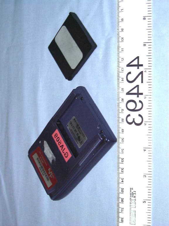
PEYBLADE2
Nov 12, 2001Bluetooth transmitter
Equipment Class
DSS - Part 15 Spread Spectrum Transmitter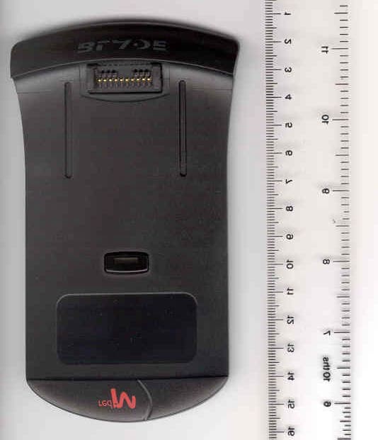
PEYBLADE1
Oct 03, 2001Bluetooth transmitter
Equipment Class
DSS - Part 15 Spread Spectrum Transmitter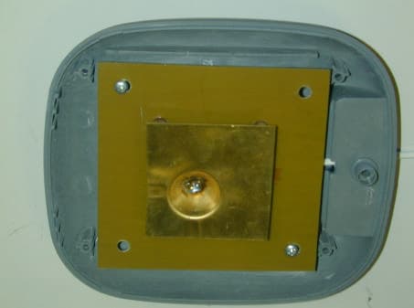
PEY3000AS2
Jul 03, 2001Bluetooth Access Server
Equipment Class
DSS - Part 15 Spread Spectrum Transmitter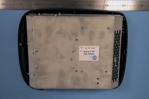
PEY3000AS
Mar 20, 2001Bluetooth Access Server
Equipment Class
DSS - Part 15 Spread Spectrum Transmitter