PEY3000ASBluetooth Access Server
Red-M (Communications) Limited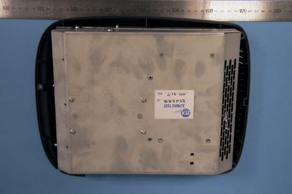
Click to zoom
Application Details
- Equipment Class
- DSS - Part 15 Spread Spectrum Transmitter
- Date of Grant
- Mar 20, 2001
- Application Purpose
- Original Equipment
- Date of Application
- Mar 20, 2001
- Equipment Note
- Bluetooth Access Server
- Frequency Range
- 2402.00000000 - 2480.00000000
- Country
- United Kingdom
Documents & Files
Document Text
Text extracted from the exhibit documents filed with the FCC. Open a document above to read the original.
Users Manual
Safety and Regulatory Information This section lists required safety, conformity and regulatory information for certain jurisdictions. For the latest and updated information, please refer to the ratings plate on the Red-M 3000AS access server. European Economic Area United States Canada European Economic Area See the (currently unsigned) Certificate of Conformity. (Requires Adobe Acrobat Reader.) We, Red-M, declare under our sole responsibility that the 3000AS is in conformity with the provisions of Council Directive 1999/5/EC on radio equipment and telecommunications terminal equipment and the mutual recognition of their conformity. This equipment is intended to be used in all Member States of the European Economic Area (EEA). It is intended to be directly connected to BRI ISDN public telecommunications network interfaces in all EEA Member States with the exception of Sweden and Norway. In these countries it may only be indirectly connected behind a device providing supplementary insulation for a primary circuit between the ISDN port of this product and the ISDN network interface as detailed in the relevant special national conditions of EN60950: 1992 clause 6.2.1.2. It is designed to connect to "Bluetooth" compatible radio interfaces using the 2.4 GHz frequency band in all EEA Member States with the exception of France where the use of the following frequencies is restricted: 2.4000 - 2.4460 GHz - Use Excluded - Military Band 2.4540 - 2.4835 GHz - Limited to indoor video applications [Member States of the EEA are: Austria, Belgium, Denmark, Finland, France, Germany, Greece, Iceland, Ireland, Italy, Luxembourg, Liechtenstein, Netherlands, Norway, Portugal, Spain, Sweden, Switzerland, United Kingdom.] United States This equipment complies with part 15 of the FCC rules. Any changes or modifications not expressly approved by the manufacturer could void the user's authority to operate the equipment. This equipment complies with Part 68 of the FCC rules. On the rear of this equipment is a label that contains, among other information, the FCC registration number for this equipment. If requested, the following information must be provided to the telephone company. FCC Registration Number: RDMGTB-40289-XD-N Ringer Equivalence Number (REN): N/A Facility Interface Code (FIC): Connects to 02IS5 via NT1/NTCE Service Order Code (SOC): 6.0Y USOC Jack Type: Connects via NT1/NTCE using RJ11C, RJ21X or RJ49C An FCC compliant telephone cord and modular plug is provided with this equipment. This equipment is designed to be connected to the telephone network or premises wiring using a compatible modular jack that is Part 68 compliant. See Installation Instructions for details. If this equipment, 3000AS, causes harm to the telephone network, the telephone company will notify you in advance that temporary discontinuance of service may be required. But if advance notice isn't practical, the telephone company will notify the customer as soon as possible. Also, you will be advised of your right to file a complaint with the FCC if you believe it is necessary. The telephone company may make changes to its facilities, equipment, operations or procedures that could affect the operation of the equipment. If this happens the telephone company will provide advance notice so you can make the necessary modifications to maintain uninterrupted service. If trouble is experienced with this equipment, 3000AS, for repair or warranty information, please contact Red-M, 860 Hillview Ct, Suite 260, Milpitas CA 95035, USA (+1 800 606 2343). If the equipment is causing harm to the telephone network, the top telephone company may request that you disconnect the equipment until the problem is resolved. Connection to party line service is subject to state tariffs. (Contact the state public utility commission, public service commission or corporation commission for information.) It is strongly suggested that an AC surge arrestor is installed in the AC outlet to which this equipment is connected. CAUTION: To reduce the risk of fire, use only No. 26 AWG or larger telecommunication line cord. To conform with FCC rules regarding RF exposure, this equipment should be installed a minimum of 20cm away from any personnel. Canada NOTICE: The Industry Canada label identifies certified equipment. This certification means that the equipment meets telecommunications network protective, operational and safety requirements as prescribed in the appropriate Terminal Equipment Technical Requirements document(s). The Department does not guarantee the equipment will operate to the user's satisfaction. Before installing this equipment, users should ensure that it is permissible to be connected to the facilities of the local telecommunications company. The equipment must also be installed using an acceptable method of connection. The customer should be aware that compliance with the above conditions may not prevent degradation of service in some situations. Repairs to certified equipment should be coordinated by a representative designated by the supplier. Any repairs or alterations made by the user to this equipment, or equipment malfunctions, may give the telecommunications company cause to request the user to disconnect the equipment. Users should ensure for their own protection that the electrical ground connections of the power utility, telephone lines and internal metallic water pipe system, if present, are connected together. This precaution may be particularly important in rural areas. Caution: Users should not attempt to make such connections themselves, but should contact the appropriate electric inspection authority, or electrician, as appropriate. top Operation is subject to the following two conditions: [1] this device may not cause harmful interference, and [2] this device must accept any interference, including interference that may cause undesired operation of the device. This device has been designed to operate with an antenna having a maxi…
Text truncated - open the document above for the full version.
Block Diagram
BIG02D.sch-1 - Mon Nov 27 15:00:32 2000
Cover Letter(s)
Page 1 of 2 3/23/01 Barry C. Quinlan From:"Ben Wrigley" <[email protected]> To:"'Certification Manager'" <[email protected]> Sent:Thursday, March 22, 2001 6:42 AM Subject:RE: Confidentiality Jon Just to confirm that Red-M wish to proceed with the FCC Part 15 application for the 3000AS and understand that in filing this application the RFI test report ref: RFI/EMCB1/RP41715C, will not be covered by the confidentiality agreement. Thanks again for your help with this project. Regards Ben Wrigley Senior Approvals Specialist KTL Saxon Way Priory Park West Hull HU13 9PB UK Phone: +44 (0)1482 801801 Fax: +44 (0)1482 801806 GSM: +44 (0)7802 280914 Email: mailto:[email protected] Web: http://www.ktl.com -----Original Message----- From: Certification Manager [mailto:[email protected]] Sent: 22 March 2001 00:11 To: Ben Wrigley Subject: Confidentiality Dear Ben, As I prepared the materials for uploading I have encountered an issue I need your confirmation on before I proceed. Red M has requested confidentiality for their test report and made a rather strong case in the letter that they would be damaged severely if it was disclosed. The FCC will not allow any test report to be identified as confidential. If we file it will be available on the FCC web site for the world to download. I have granted this application and I am required to upload the test report and all other exhibits within 5 days. If I do not hear from you within 2 days that the uploading of the test report is allowed by Red M, then I will withdraw the grant. Normally I would have waited and asked, but I know Red M is under a lot of pressure to get this grant Page 2 of 2 3/23/01 and I anticipate that they will be willing to disclose the test report in order to gain access to the US market. Jon. Best regards Barry C. Quinlan Certification & Telecom Manager ------------------------------------------------------------------------------- Curtis-Straus LLC Voice: 978.486.8880 x270 527 Great Road Fax: 978.486.8828 Littleton, MA 01460 http://www.curtis-straus.com --------------------------------------------------------------------------------
Cover Letter(s)
Hi Ben, We have completed our review of the application and we have identified the following issues: 1. The conducted output power appears to have been acquired using a resolution bandwidth of 100kHz. The transmission bandwidth is 1MHz. Please provide the transmitter output power in the highest channel using a resolution bandwidth which is larger than the transmission bandwidth. RESPONSE: The data was taken at 1MHz. The report refers to Graph 001 but it should be Graph 004. (FCC Part 15.247(b) is also referenced on the bottom of this graph.) 2. Please provide a measurement of the bandedge field strength at 2483.5 MHz with the product operating in the highest channel. We need to confirm that this meets the 15.205 limits. RESPONSE: (FROM TCB – The applicant has shown that he measured emissions that were slightly removed from the band edge and found them to be below the limit. These emissions were higher than the level at the band edge and thus the bandedge is compliant. We accept this rationale). For the internal antenna refer to graph 049, frequency span from 2.39 to 2.5 GHz. The band 2.4835 to 2.5 GHz is a restricted band in the USA so only spurious emissions are allowed in the band. From graph 049 there is no spurious emission at 2.4835 GHz, there are 2 spurious emissions at 2.4937 GHz and at 2.4864 GHz. Both of these peaks were measured on the open site and the peak and average measurements reported in section 7.7.2.3. Similar data exists for the external antenna. Graph 054 shows the frequency range of interest and, again, there is no spurious emission at 2.4835 GHz but there are 2 spurious emissions are visible at 2.4894 and 2.4963 GHz. Both of these emissions were measured on the open site and the peak and average measurements reported in section 7.7.2.4. For the external antenna we have a measurement only 2.9 MHz off the actual band edge with a measurement RBW of 1 MHz with a result 11 dBuV/m BELOW the peak limit and 16 dBuV/m BELOW the average limit. For the external antenna we have a measurement only 5.9 MHz off the actual band edge with a measurement RBW of 1 MHz with a worst case result 13 dBuV/m BELOW the peak limit and 16 dBuV/m BELOW the average limit. 3. Please provide data responsive to the 15.31 (e) requirement. RESPONSE: Blue tooth voltage variation test report provided. 4. Please provide an MPE calculation to document the units RF exposure compliance. RESPONSE: MPE Calculation exhibit provided. 5. Please supply details of the label material. RESPONSE: I can confirm that KTL have assessed the label material used both for compliance with FCC Part 68 and also to the requirements of IEC60950 and UL1950 for durability and legibility. Furthermore the 3000AS is FCC certified to Part 68 under FCC Reg: RDM GTB - 40289 - XD - N. 6. Please supply details of the external antenna connector so we can check for compliance with 15.203. RESPONSE: The external antenna uses an MCX type connector which is currently classed by the FCC as not readily available.
External Photos
Index of External Photographs 1. General external front view 2. General external side view – connectors visible 3. General external rear view 4. General internal front view – plastic outer enclosure removed 1 2 3 4
Internal Photos
Index of Internal Photographs 1. General internal top view – plastic outer enclosure removed – Bluetooth radio module visible 2. General internal bottom view – plastic outer enclosure removed 3. General internal view – main PCB visible 4. General internal view – hard drive and power supply visible 5. Main PCB – component side 6. Main PCB – solder side 7. Bluetooth radio module PCB – component side 8. Bluetooth radio module PCB – solder side 1 2 3 4 5 6 7 8
Operational Description
Bluetooth radio and baseband operation: a summary Bluetooth operates using frequency hopping spread spectrum techniques (FHSS) with Gaussian frequency shift keying (GFSK). The parameters of these techniques are described in more detail below. For more information please refer to the Radio and Baseband specification chapters of the Bluetooth Core specification at http://www.bluetooth.com/developer/specification/Bluetooth_11_Specifications_Book.pdf Bluetooth channel definition The Bluetooth channel is represented by a pseudo-random hopping sequence hopping through 79 RF channels. The hopping sequence is unique for each piconet (a group of units comprising a master and up to 7 slaves all sharing the same channel) and is determined by the Bluetooth device address of the master; the phase in the hopping sequence is determined by the Bluetooth clock of the master. The channel is divided into time slots where each slot corresponds to an RF hop frequency. Consecutive hops correspond to different RF hop frequencies. The nominal hop rate is 1600 hops/s. All Bluetooth units participating in the piconet are time- and hop- synchronized to the channel. Time slots The channel is divided into time slots, each 625 ms in length. The time slots are numbered according to the Bluetooth clock of the piconet master. The slot numbering ranges from 0 to 2 27 -1 and is cyclic with a cycle length of 2 27 . In the time slots, master and slave can transmit packets. A time division duplex scheme is used where master and slave alternatively transmit. The master shall start its transmission in even-numbered time slots only, and the slave shall start its transmission in odd-numbered time slots only. The packet start shall be aligned with the slot start. Packets transmitted by the master or the slave may extend over up to five time slots. The RF hop frequency shall remain fixed for the duration of the packet. For a single packet, the RF hop frequency to be used is derived from the current Bluetooth clock value. For a multi-slot packet, the RF hop frequency to be used for the entire packet is derived from the Bluetooth clock value in the first slot of the packet. The RF hop frequency in the first slot after a multi-slot packet shall use the frequency as determined by the current Bluetooth clock value. If a packet occupies more than one time slot, the hop frequency applied shall be the hop frequency as applied in the time slot where the packet transmission was started. Modulation and bit rate The data transmitted has a symbol rate of 1 Ms/s. A Gaussian-shaped, binary FSK modulation is applied with a BT product of 0.5. A binary one is represented by a positive frequency deviation, a binary zero by a negative frequency deviation. The maximum frequency deviation shall be between 140 kHz and 175 kHz. Modulation and characteristics The Modulation is GFSK (Gaussian Frequency Shift Keying) with a BT=0.5. The Modulation index must be between 0.28 and 0.35. A binary one is represented by a positive frequency deviation, and a binary zero is represented by a negative frequency deviation. The symbol timing shall be better than ±20 ppm. For each transmit channel, the minimum frequency deviation (Fmin = the lesser of {Fmin+, Fmin-}) which corresponds to 1010 sequence shall be no smaller than ±80% of the frequency deviation (fd) which corresponds to a 00001111 sequence. In addition, the minimum deviation shall never be smaller than 115 kHz. The zero crossing error is the time difference between the ideal symbol period and the measured crossing time. This shall be less than ± 1/8 of a symbol period.
Operational Description
SiW1502 Data Sheet Preliminary Information November 3, 2000 60 0010 R00B SiW1502 DS Page 1 of 21Silicon Wave, Inc. SiW1502 Radio Modem IC 1. INTRODUCTION The SiW1502 Radio Modem IC is part of Silicon Wave's Odyssey™ solutions for Bluetooth™ wireless communications. The SiW1502 IC combines a 2.4-GHz radio transceiver and GFSK modem with digital control functions meeting Bluetooth specifications. The SiW1502 IC is designed to work with the Silicon Wave SiW1601 Link Controller IC or other compatible IC to enable production of Bluetooth wireless communication products. 2. FEATURES • Radio and modem with combined RF analog and digital CMOS circuits on a single integrated silicon chip. • Fully compliant with Bluetooth Specification 1.0 B. • Pin-to-pin compatibility with the SiW1501. • Direct-conversion radio architecture with integrated VCO and frequency synthesizer requiring minimal external components. • Integrated analog-digital conversion circuits transform I/O signals between the radio and GFSK modem. • Integrated GFSK modem with digital modulation, channel filtering, AFC, symbol timing recovery, and bit slicer. • Integrated 0 dBm transmit driver with eight output power levels. • Direct interface to Bluetooth controller ICs through a low pin-count, digital interface. • Optimized design for low power consumption, low cost, and small size. 3. APPLICATIONS The SiW1502 Radio Modem is suitable for all applications requiring a Bluetooth-compliant radio link in a low-power and cost-effective implementation. • Cellular Use: mobile phone handset integration and accessories. • Office: office PCs, notebook PCs, and laser printer interconnection. • Personal Data: PDA, palmtop, and personal organizer communications. • Consumer: digital cameras, handheld game units. • Automotive: hands-free car kit. Radio Modem ICSiW1502 Data Sheet Preliminary Information November 3, 2000 60 0010 R00B SiW1502 DS Page 2 of 21Silicon Wave, Inc. 4. DESCRIPTION Figure 1 shows the functional block diagram. During the receive process, the radio signal is taken from a pair of balanced RF I/O pins that feed into the low noise amplifier (LNA). Direct I/Q down conversion and on-chip filtering send the processed I/Q data to the analog-to-digital converter before processing by the GFSK demodulator. Within the demodulator, data detection and timing recovery circuits convert the data for transfer to an external device. The transmit process operates in a similar fashion in reverse order. Digital control functions and a programming interface provide radio modem control and a flexible interface to external Bluetooth link controller ICs. For efficient power management, each section of the radio may be powered down when not in use. The active circuitry required for the master clock reference and low-power clock used to supply clock signals to external devices is located on the SiW1502. The transmitted signal is GFSK modulated data that is amplified on the chip to yield a radiated output of 0 dBm. A power control signal for an external amplifier is provided. EXT_PA_CNTL System Control Logic MODEM_TX_DATA MODEM_RX/TX_DATA MODEM_CD/TXEN MODEM_RX_CLK Baseband Interface RF Interface RF_IN/OUT+ RF_IN/OUT- TX_RX_SW ITCH /RESET_RM ENABLE_RM HOP_STRB Clock Generation and Distribution 32KHZ_CLK BB_CLK 32MHZ_XTL 32KHZ_XTL BB_CLK_MODE Data SPI_TXD SPI_CLK /SPI_SS SPI_RXD Serial Program ming Interface (SPI) Register File GFSK MODEM LNA ADC ADC Driver VCO/ PLL PWR CNTL DAC DAC 0 90 0 90 Control Control Figure 1: SiW1502 IC Block Diagram Radio Modem ICSiW1502 Data Sheet Preliminary Information November 3, 2000 60 0010 R00B SiW1502 DS Page 3 of 21Silicon Wave, Inc. 5. PIN DESCRIPTION The SiW1502 IC’s radio and modem interface, the Serial Programming Interface (SPI), and the two clock inputs are required for proper operation. 5.1. Radio Interface The radio interface provides an antenna connection through external circuitry to transmit and receive the Bluetooth radio signals. Control signals for the external transmit/receive switch and optional power amplifier are available. NOTE: The RF signals occupy special pin locations on the device package. For an example, please refer to the application circuit in Section 8 on page 15. External impedance matching and balun circuits are required to complete the interface to the antenna. Please refer to Figure 10 in Section 8 for the recommended external circuit details. NameDirectionDescription RF_IN/OUT+I/OPositive RF input and output pin. RF_IN/OUT-I/ONegative RF input and output pin. EXT_PA_CNTLO Power control to external power amplifier. This output provides a variable current source that can be used to control the external power amp. TX_RX_SWITCHO Output to select external transmit/receive switch circuit for external PA (20 dBm) configurations. High = Receive Low = Transmit Table 1: Signal Description 5.2. Modem Interface The modem interface transfers the Bluetooth data between the SiW1502 and an external controller such as the SiW1601 IC. The programmable interface on the SiW1502 can be set to various operating modes, depending on the desired interface usage. Programming of the interface is done through internal registers. For reference purposes, Table 2 provides a brief description of typical interface modes. NameDirectionDescription MODEM_TX_DATAITransmit Data. MODEM_RX_DATAI/O This pin has three possible programmable mode settings (through internal registers): 1. Symbol synchronized received data at 1 MHz. 2. Sliced receive data at 8 MHz (sliced output). 3. Both transmit and receive data for low pin-count mode. MODEM_CD/TXENI/ODual function carrier detect and transmit enable. This bi-directional signal can be enabled through internal registers. During transmit, this pin can be used as an INPUT to indicate valid transmit data (TXEN). During receive, this pin can be used as OUTPUT to indicate carrier detect (CD). Table 2: Modem Interface Signal Description Radio Modem ICSiW1502 Data Sheet Preliminary Informat…
Text truncated - open the document above for the full version.
RF Exposure Info
Red-M Wexham Springs . Framewood . Framewood Road . Wexham . Slough . SL3 6PJ Tel: +44 (0)1753 661700 Fax: +44 (0)1753 661745 www.red-m.com Maximum Permissable Exposure Calculations. The following calculations are based on guidelines published in OET Bulletin 65, Edition 97-01, August 1997: Evaluating Compliance with FCC Guidelines for Human Exposure to Radiofrequency Electromagnetic Fields. Near to Far Field Frequency (GHz) Wavelength (m) Transition (cm) Lower 2.4000 0.125 ~2.0 Upper 2.4835 0.121 ~1.9 For a simple case, discounting reflections, equation 3, page 19 gives: Power Density= PG/ 4πR² Maximum transmitter output power: 7.34 dBm. Power input to antenna : 5.42 mW. Antenna gain : 0 dBi. Numeric antenna gain : 1. Distance from antenna : 20 cm. ∴ Power Density= 0.001 mW/cm². General population/ uncontrolled limit= 1mW/cm². Notes. 1. The maximum transmitter output power is that measured for FCC Part 15.247(b3). 2. The distance from the antenna, 20 cm, is taken from the minimum working distance quoted in the user manual, required by the FCC. 3. The general population/ uncontrolled limit is taken from OET 65, Appendix A Table 1B page 67. Red-M Wexham Springs . Framewood . Framewood Road . Wexham . Slough . SL3 6PJ Tel: +44 (0)1753 661700 Fax: +44 (0)1753 661745 www.red-m.com For a truly worst case prediction of power density, including reflections from nearby surfaces, OET 65 recommends using equation 6, page 20. Power Density S= PG/πR² Using the same figures as above the worst case estimate power density is: S= 0.004 mW/cm². Mark Bailey 20/03/01 Red-M Ltd.
Test Report
Radio Frequency Investigation Ltd, Ewhurst Park, Ramsdell, Basingstoke, Hampshire, RG26 5RQ, ENGLAND. Tel: +44 (0) 1256 851193 Fax: +44 (0) 1256 851192 Registered in England, No. 211 7901. Registered Office: Ewhurst Park, Ramsdell, Basingstoke, Hampshire RG26 5RQ TESTING 0644 TEST REPORT FROM RADIO FREQUENCY INVESTIGATION LTD. Test Of: Red-M (Communications) Ltd. 3000AS Wireless Internet Server with Access Server External Aerial (3000-501) To: F.C.C. Part 15 Subpart C: 1998 (Intentional Radiators) Section 15.247 Test Report Serial No: RFI/EMCB1/RP41715C This Test Report Is Issued Under The Authority Of Brian Watson Technical Director: Checked By: Tested By: p.p Release Version No: PDF01 Issue Date: 28 February 2001Test Date: 5 December 2000 to 8 December 2000 This report is issued in Adobe Acrobat portable document format (PDF). It is only a valid copy of the report if it is being viewed in PDF format with the following security options not allowed: Changing the document, Selecting text and graphics, Adding or changing notes and form fields. Furthermore, the date of creation must match the issue date stated above. This report may be copied in full. RADIO FREQUENCY INVESTIGATION LTD.TEST REPORT S.No. RFI/EMCB1/RP41715C EMC DepartmentPage 2 of 38 Issue Date: 28 February 2001 Test Of:Red-M (Communications) Ltd. 3000AS Wireless Internet Server with Access Server External Aerial (3000-501) To:F.C.C. Part 15: 1998 Subpart C (Intentional Radiators). Section 15.247 This page has been left intentionally blank. RADIO FREQUENCY INVESTIGATION LTD.TEST REPORT S.No. RFI/EMCB1/RP41715C EMC DepartmentPage 3 of 38 Issue Date: 28 February 2001 Test Of:Red-M (Communications) Ltd. 3000AS Wireless Internet Server with Access Server External Aerial (3000-501) To:F.C.C. Part 15: 1998 Subpart C (Intentional Radiators). Section 15.247 Table of Contents 1. Client Information...............................................................................................................4 2. Equipment Under Test (EUT)...........................................................................................5 3. Test Specification, Methods And Procedures..............................................................7 4. Deviations From The Test Specification........................................................................9 5. Operation Of The EUT During Testing.........................................................................10 6. Summary Of Test Results...............................................................................................11 7. Measurements, Examinations And Derived Results.................................................12 8. Measurement Uncertainty...............................................................................................26 Appendix 1. Test Equipment Used.....................................................................................27 Appendix 2. Measurement Methods..................................................................................28 Appendix 3. Test Configuration Drawings........................................................................34 RADIO FREQUENCY INVESTIGATION LTD.TEST REPORT S.No. RFI/EMCB1/RP41715C EMC DepartmentPage 4 of 38 Issue Date: 28 February 2001 Test Of:Red-M (Communications) Ltd. 3000AS Wireless Internet Server with Access Server External Aerial (3000-501) To:F.C.C. Part 15: 1998 Subpart C (Intentional Radiators). Section 15.247 1. Client Information Company Name:Madge Networks Ltd. Address: Red M Division Wrexham Springs Framewood Road Wexham Slough Berks SL3 6PJ United Kingdom. Contact Name:Mr C. O’Brien. RADIO FREQUENCY INVESTIGATION LTD.TEST REPORT S.No. RFI/EMCB1/RP41715C EMC DepartmentPage 5 of 38 Issue Date: 28 February 2001 Test Of:Red-M (Communications) Ltd. 3000AS Wireless Internet Server with Access Server External Aerial (3000-501) To:F.C.C. Part 15: 1998 Subpart C (Intentional Radiators). Section 15.247 2. Equipment Under Test (EUT) The client has supplied the following information (with the exception of the Date of Receipt): 2.1. Identification Of Equipment Under Test (EUT) Brand Name:Red-M Model Name or Number:3000AS Unique Type Identification:Not applicable Serial Number:00028110400A0 Country of Manufacture:UK FCC ID Number:Pending Date of Receipt:5 December 2000 Brand Name:Red-M Model Name or Number:Access Server External Aerial (3000-501) Unique Type Identification:Not applicable Serial Number:1 Country of Manufacture:UK FCC ID Number:Pending Date of Receipt:5 December 2000 2.2. Description Of EUT The 3000AS is a Bluetooth Access Server. It provides connectivity between Bluetooth devices, LAN and WAN. The product has an in-built Bluetooth antenna and the option for the connection of an external antenna. 2.3. Modifications Incorporated In EUT The EUT has not been modified from what is described by the Model Name and Unique Type Identification stated above. RADIO FREQUENCY INVESTIGATION LTD.TEST REPORT S.No. RFI/EMCB1/RP41715C EMC DepartmentPage 6 of 38 Issue Date: 28 February 2001 Test Of:Red-M (Communications) Ltd. 3000AS Wireless Internet Server with Access Server External Aerial (3000-501) To:F.C.C. Part 15: 1998 Subpart C (Intentional Radiators). Section 15.247 2.4. Support Equipment The following support equipment was used to exercise the EUT during testing: Description:10/100 Switch Brand Name:3COM Model Name or Number:3 Com Office Connect Dual Speed Hub 8 Serial Number:0101/7P1F67471 FCC ID Number:None stated Cable Length And Type:3m, 10/100 Type Connected to Port:10/100 RADIO FREQUENCY INVESTIGATION LTD.TEST REPORT S.No. RFI/EMCB1/RP41715C EMC DepartmentPage 7 of 38 Issue Date: 28 February 2001 Test Of:Red-M (Communications) Ltd. 3000AS Wireless Internet Server with Access Server External Aerial (3000-501) To:F.C.C. Part 15: 1998 Subpart C (Intentional Radiators). Section 15.247 3. Test Specification, Methods And Procedures 3.1. Test Specification Reference:FCC Part 15 Subpart C: 1998 Sec…
Text truncated - open the document above for the full version.
Test Report
RADIO FREQUENCY INVESTIGATION LTD.TEST REPORT Graphical Test Results S.No. RFI/EMCB1/RP41715C EMC DepartmentIssue Date: 28 February 2001 Test Of:Red-M (Communications) Ltd. 3000AS Wireless Internet Server with Access Server External Aerial (3000-501) To:F.C.C. Part 15: 1998 Subpart C (Intentional Radiators). Section 15.247 Appendix 4. Graphical Test Results (Part 1a) This appendix contains the following graphs: Graph Reference NumberTitle GPH\41715ETF04\001 Radiated Emissions, Hopping all frequencies (2.39 GHz to 2.49 GHz) Section 15.247 (a) GPH\41715ETF04\002Radiated Emissions, Hopping all frequencies (2.438577451 GHz to 2.440974999 GHz) Section 15.247 (a) GPH\41715ETF04\003Radiated Emissions, Hopping all frequencies (2.43675 GHz to 2.43925 GHz) Section 15.247 (a) GPH\41715ETF04\004Radiated Emissions, Hopping all frequencies (2.4355 GHz to 2.4405 GHz) Section 15.247 (b) GPH\41715ETF04\005Radiated Emissions, Hopping …
Text truncated - open the document above for the full version.
Contact Information
Applicant
Mark Bailey(Senior Approvals Engineer)
Test Firm
RFI Global Services Ltd.Allan Hume
Technical Specifications
| # | Rule Parts | Frequency Range | Power Output |
|---|---|---|---|
| 1 | 15C | 2.40 GHz - 2.48 GHz | 5.40 mW |
Other Applications from Red-M (Communications) Limited
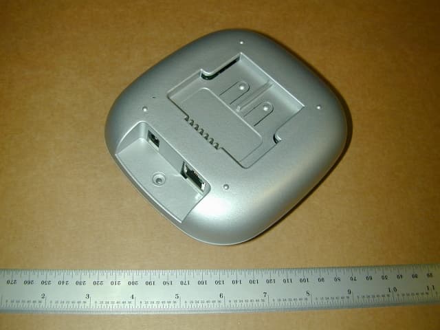
PEY13741
Jun 02, 2003950AP Bluetooth Device
Equipment Class
DSS - Part 15 Spread Spectrum Transmitter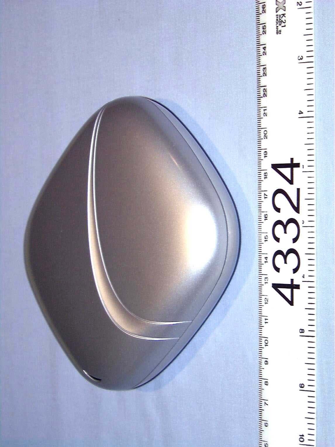
PEY1150AP
Jun 01, 2002Bluetooth Access Point
Equipment Class
DSS - Part 15 Spread Spectrum Transmitter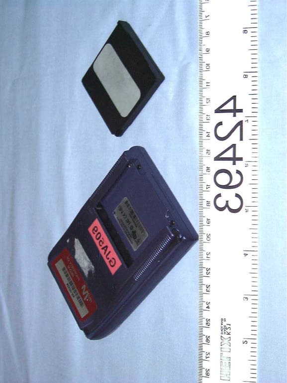
PEYBLADE2
Nov 12, 2001Bluetooth transmitter
Equipment Class
DSS - Part 15 Spread Spectrum Transmitter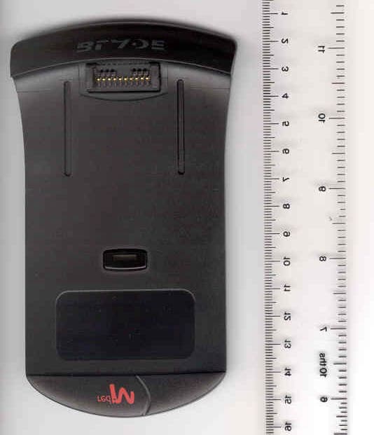
PEYBLADE1
Oct 03, 2001Bluetooth transmitter
Equipment Class
DSS - Part 15 Spread Spectrum Transmitter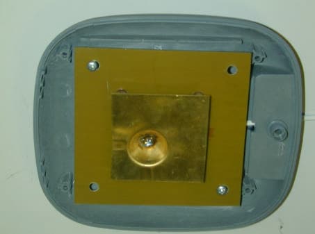
PEY3000AS2
Jul 03, 2001Bluetooth Access Server
Equipment Class
DSS - Part 15 Spread Spectrum Transmitter