PEYBLADE2Bluetooth transmitter
Red-M (Communications) Limited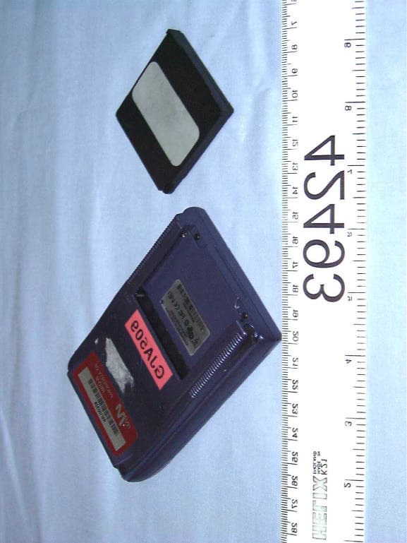
Click to zoom
Application Details
- Equipment Class
- DSS - Part 15 Spread Spectrum Transmitter
- Date of Grant
- Nov 12, 2001
- Application Purpose
- Original Equipment
- Date of Application
- Nov 12, 2001
- Equipment Note
- Bluetooth transmitter
- Frequency Range
- 2402.00000000 - 2480.00000000
- Country
- United Kingdom
Documents & Files
Document Text
Text extracted from the exhibit documents filed with the FCC. Open a document above to read the original.
Users Manual
43 43 Technical support and contact information Technical support and contact information For Red-M Blade support information, visit the Red-M website at www.red-m.com/blade Regulatory information The following regulatory statements apply to the Red-M Blade - Bluetooth module for Handspring Visor. North America By attaching themark to this product, we confirm: This equipment complies with Part 15 of the FCC rules. Operation is subject to the following two conditions: (1) this device may not cause harmful interference, and (2) this device must accept any interference received, including interference that may cause undesirable operation. IMPORTANT NOTE: To comply with FCC RF exposure compliance requirements, the following antenna installation and device operating configurations must be satisfied: The device and its antenna must not be co-located or operating in conjunction with any other antenna or transmitter. Any changes or modifications not expressly approved by the manufacturer could void the user’s authority to operate the equipment. This device has been designed to operate with an antenna that has a maximum gain of 0 dB. Antennae that have a higher gain are strictly prohibited as per regulations of Industry Canada. The required antenna impedance is 50 ohms. 44 44 To reduce potential radio interference to other users, the antenna type and its gain should be so chosen that the equivalent isotropically radiated power (EIRP) is not more than that required for successful communication. To prevent radio interference to the licensed service in Canada, this device is intended to be operated indoors and away from windows to provide maximum shielding. Equipment (or its transmit antenna) that is installed outdoors is subject to licensing. Europe (EEA) This product is designed to connect to "Bluetooth" compatible radio interfaces using the 2.4 GHz frequency band in all EEA Member States with the exception of France where the use of the following frequencies is restricted: 2.4000 - 2.4460 GHz - Use Excluded - Military Band 2.4540 - 2.4835 GHz - Limited to indoor video applications [Member States of the EEA are: Austria, Belgium, Denmark, Finland, France, Germany, Greece, Iceland, Ireland, Italy, Luxembourg, Liechtenstein, Netherlands, Norway, Portugal, Spain, Sweden, Switzerland, United Kingdom. 45 45 Regulatory information 46 46 Power supply information English CAUTION: Only use this product with a power source that meets the "Limited Power Source" requirements of IEC 60950 or equivalent safety standards. Use the power supply provided (if applicable) or contact Red-M for a list of suitable power sources. Dansk ADVARSEL: Dette produkt må kun anvendes sammen med strømkilder, der opfylder kravene vedrørende "Limited Power Source" i IEC 60950 eller tilsvarende sikkerhedsstandarder. Anvend den medfølgende strømforsyning (hvis muligt), eller kontakt Red-M og få en liste over godkendte strømkilder. Deutsch WARNUNG: Verwenden Sie dieses Produkt nur mit einer Stromquelle, die die Anforderungen bezüglich "begrenzter Stromquellen" gemäß IEC 60950 oder entsprechender Sicherheitsnormen erfüllt. Verwenden Sie das im Lieferumfang enthaltene Netzteil (sofern zutreffend), oder fordern Sie bei Red-M eine Liste der geeigneten Stromquellen an. Español PRECAUCIÓN: Emplee este producto únicamente con una fuente de alimentación que cumpla la norma de seguridad IEC 60950 de alimentación limitada, o equivalente. Utilice la fuente de alimentación suministrada, si es el caso, o consulte a Red-M para obtener una lista de fuentes de alimentación apropiadas. Flemish OPGELET: gebruik dit product enkel met een voedingsbron die voldoet aan de "Minimum voedingsbron"-vereisten van IEC 60950 of evenwaardige veiligheidsvoorschriften. Gebruik bijhorende voedingsbron (indien deze geschikt is) of neem contact op met RED-M voor een lijst van geschikte voedingsbronnen. 47 47 Regulatory information Français ATTENTION: n'utilisez ce produit qu'avec une source d'énergie conforme à la norme IEC 60950 en matière de « source d'énergie limitée », ou autre norme de sécurité équivalente. Utilisez l'alimentation en courant fournie (si applicable) ou bien contactez Red-M pour obtenir une liste des sources d'énergie adéquates. Íslenska VARÚÐ: Notið þessa vöru eingöngu með aflgjafa sem stenst kröfur í kaflanum um "aflgjafa með takmarkað afl" í IEC 60950 (ÍST EN 60950) eða sambærilegra öryggisstaðla. Notið aflgjafann sem fylgir (ef viðeigandi) eða fáið lista yfir nothæfa aflgjafa hjá umboðsaðila vörunnar. Italiano ATTENZIONE: Utilizzare questo prodotto solo con sorgenti di alimentazione che soddisfano i requisiti di sicurezza IEC 60950 o equivalenti. Utilizzare l'alimentatore fornito (ove applicabile) o contattare Red-M per ottenere un elenco delle sorgenti di alimentazione adeguate. Nederlands WAARSCHUWING: Gebruik dit product alleen met een voedingsbron die voldoet aan de "Minimum voedingsbron"-vereisten van IEC 60950 of evenwaardige veiligheidsvoorschriften. Gebruik de bijbehorende voedingsbron (indien van toepassing) of neem contact op met Red-M voor een lijst van geschikte voedingsbronnen. Norsk FORSIKTIG: Dette produktet skal bare brukes med en strømkilde som tilfredsstiller kravene til "Begrenset strømkilde" i IEC 60950 eller tilsvarende sikkerhetsstandard. Bruk den medfølgende strømforsyningen (hvis en slik finnes) eller kontakt Red-M for å få en oversikt over passende strømkilder. 48 48 Português Advertência: Utilize este produto apenas com uma fonte de energia que respeite os requisitos definidos em "Fontes de Energia Limitadas" da norma IEC 60950 ou dos padrões de segurança equivalentes. Utilize a fonte de alimentação fornecida (se aplicável) ou contacte Red-M para obter uma lista de fontes adequadas. Suomi MUISTUTUS: Käytä tätä tuotetta vain sellaisen virtalähteen yhteydessä, joka täyttää standardin 60950 "rajoitetun virtalähteen" tai muiden vastaavien standardien asettamat turvallisuusvaatimukset. Käytä toimitettua virtalähdettä (jos asi…
Text truncated - open the document above for the full version.
Block Diagram
Application Flash UART 3.6864MHz XTAL BC01b Bluetooth Baseband Controller and Radio (see exploded view) Flash Springboard Interface 16MHz XTAL Red-M Bluetooth Springboard Module Block Diagram VCO loop filter Tx Matching cct Balun Filter cct TxB TxA TxPower Rx Matching cct Rx Tx/Rx Switch Bandpass filter Antenna Regulator 3.3V3.0V Red-M Bluetooth Springboard Module Block Diagram (BC01b exploded view) XTAL_INXTAL_OUT CLOCK GENERATION BASEBAND DSP UART INTERFACE FLASH INTERFACE PHYSICAL LAYER DSP HARDWARE ENGINE DSP, MMU, RAM, UART, ETC LNA IQ DEMOD DEMOD ADC DAC IQ MOD PA PA LEVEL CONTROL +45 -45 TUNE RF SYNTHESISER /N/N+1 MICROCONTROLLER F_REF RF RECEIVER RF TRANSMITTER RF SYNTHESISER LOOP FILTER Rx TxA TxB TxPower
Cover Letter(s)
Response to TCB findings FCC ID: PEYBLADE2 Hi Mark, We have reviewed the application and have identified the following issues: 1. The processing gain (PG) data is for a different device than that for which certification is sought. The FCC has stated that processing gain data is dependent on layout and component selection. Data from the chip set alone is not enough to prove compliance. If generic data from a different device using the same chipset is to be accepted, a letter must be provided which states that the layout and all component values in the RF path are identical in the device for which data is presented. Please submit PG data for the device or submit a letter which documents that the device is identical to the device measured for processing gain. We did note the comments in your email. Response: The applicant provided the email below: Barry, attached is the response from Joe Dichoso to Chris Neal (Cambridge Silicon Radio) regarding the processing gain of the BC01 radio modem/ baseband chip. This email is the response to the one that Neil Evans forwarded to you last week. Hope this helps. Regards. Mark B > ---------- > From: David Frost > Sent: Monday, November 12, 2001 18:15 PM > To: Nick Moss (E-mail) > Subject: FW: Processing gain > > Nick > > Here is an email from Joe to Chris > > If this is no good Chris has said he will go back to Joe > > Best Regards > Dave > > -----Original Message----- > From: Chris Neal > Sent: 12 November 2001 18:08 > To: David Frost > Subject: FW: Processing gain > > -----Original Message----- > From: Joe Dichoso [mailto:[email protected]] > Sent: Friday, August 10, 2001 5:33 PM > To: [email protected] > Subject: Re: Processing gain > > > Hello Chris, > Yes transmitters that are identical will have the same processing gain. > If a device utilizes the same transmitter that has already been approved. > The processing gain exhibit can be copied from the original file. A cover > letter indicating so, should be provided with the copied document to > explain > the copied material. > > >>> Chris Neal <[email protected] > 08/06/01 11:45AM >>> > Joe > > Good to talk to you just now. During our conversation we discussed the > top > level architecture of a Bluetooth module built with CSR's BC01 chip. We > talked about the fact that a module's Bluetooth functionality is > completely > determined by the BC01 chip which features an integral transmitter, > receiver > and the processing gain filters. All BC01 based modules will therefore > have > identical processing gains. > > A processing gain report for a BC01 module has already been filed and may > be found on the FCC's website under FCC ID O2Z-BT2. You have proposed > that > this report be reused for future submissions covering new BC01 based > modules. Adopting this approach will save having to repeat the processing > gain measurements. > > In line with the above and your recent Bluetooth exhibit (guidance note), > I > propose to advise our customers that their FCC submission file for BC01 > should contain module specific evidence for: > > 1) The occupied bandwidth in Section 15.247(a)(1)(ii). > 2) Conducted output power specified in Section 15.247(b)(1). > 3) EIRP limit in Section 15.247(b)(3). > 4) RF safety requirement in Section 15.247(b)(4) > 5) Spurious emission limits in Section 15.247(c) > 6) Power spectral density requirement in Section 15.247(f) in the > acquisition mode. > > Our customers should append to this a pdf version of the processing gain > report taken from FCC ID O2Z-BT2 together with a brief explaination of why > the processing gain of their module is identical to that of other BC01 > equipped modules - along the lines outlined above. > > I believe this is what we agreed. Please could you confirm or otherwise > by > return email. > > Thanks once again for taking the time to follow this through with me. > > > > Chris Neal > > > > > ********************************************************************** > The information transmitted is intended only for the person or > entity to which it is addressed and may contain confidential > and/or privileged material. > Any review, retransmission, dissemination or other use of, or > taking of any action in reliance upon, this information by > persons or entities other than the intended recipient is > prohibited. > If you received this in error, please contact the sender and > delete the material from any computer. > ********************************************************************** > > This message contains information which may be confidential and privileged. Unless you are the addressee (or authorised to receive for the addressee), you should not use, copy or disclose to anyone the details or information contained in this message. The content of the message and or attachments may not reflect the view and opinions of the originating company. If you have received this message in error, you should reply to the sender and copy [email protected] and delete the message from your system. Thank you for your co-operation. 2. Please split the photos exhibit into 3 - external, internal and test setup. As the file is protected I was unable to do this. Response: Separate files provided. Best regards Barry C. Quinlan Certification & Telecom Manager ------------------------------------------------------------------------------- Curtis-Straus LLC Voice: 978.486.8880 x270 527 Great Road Fax: 978.486.8828 Littleton, MA 01460 http://www.curtis-straus.com --------------------------------------------------------------------------------
External Photos
Radio Frequency Investigation Ltd, Ewhurst Park, Ramsdell, Basingstoke, Hampshire, RG26 5RQ, ENGLAND. Tel: +44 (0) 1256 851193 Fax: +44 (0) 1256 851192 Registered in England, No. 211 7901. Registered Office: Ewhurst Park, Ramsdell, Basingstoke, Hampshire RG26 5RQ TESTING 0644 EXTERNAL PHOTOGRAPH SECTION FOR RFI TEST REPORT SERIAL NO: RFI/MPTB1/RP42493B Test Of: Red-M (Communications) Ltd. Bluetooth Module for Visor To: F.C.C. Part 15 Subpart C: 2000 (Intentional Radiators) Section 15.247 RADIO FREQUENCY INVESTIGATION LTD.External Photograph Section S.No: RFI/MPTB1/RP42493B EMC Department Test Of:Red-M (Communications) Ltd. Bluetooth Module for Visor To:F.C.C. Part 15 Subpart C: 1998 (Intentional Radiators) Section 15.247 This section contains the following photographs: Photo Reference NumberTitle PHT/42493JD13/001Front view of EUT PHT/42493JD13/002Rear view of EUT These pages are not included in the total number of pages for this report. RADIO FREQUENCY INVESTIGATION LTD.External Photograph Section S.No: RFI/MPTB1/RP42493B EMC Department Test Of:Red-M (Communications) Ltd. Bluetooth Module for Visor To:F.C.C. Part 15 Subpart C: 1998 (Intentional Radiators) Section 15.247 PHT/42493JD13/001 Front view of EUT External Photos RADIO FREQUENCY INVESTIGATION LTD.External Photograph Section S.No: RFI/MPTB1/RP42493B EMC Department Test Of:Red-M (Communications) Ltd. Bluetooth Module for Visor To:F.C.C. Part 15 Subpart C: 1998 (Intentional Radiators) Section 15.247 PHT/42493JD13/002 Rear view of EUT External Photos
ID Label/Location Info
Serial Number / Bluetooth Address: 000281 DDDDDE Assembly: 158-239-01 Made in Ireland 1 5 8 - 2 4 0 - 0 2 © Red-M 2001. Patents Pending ARTWORK All detail within this box to be printed except that shown in RED. Any detail in GREEN to be printed but see notes for specific content. Notes: (1) Serial Numbers increment in steps of 1. Specific range of values will be specified with order. (2) Artwork to be made from CorelDraw (.CDR) format. PDF format for inspection only. (3) Barcode is format Code39 and comprises a Single Character Prefix as defined above followed by the right-hand 6 characters of “Serial No. / Bluetooth Addr” (eg “ZDDDDDE” where “Z” is the Single Character Prefix). Artwork - Red-M Rating Plate Label Bluetooth Module for Handspring Visor, CE + US/Canada/CSA + Bluetooth mark 158-240-02 158-131-01 Artwork Revision A RevDateBy 17/10/01NE First Approvals TITLE: USE BLANK STOCK: VERSION: ARTWORK/LABEL PART NUMBER: Red-M Wexham Springs Framewood Road Wexham Slough SL3 6PJ England Copyright 2001 Red-M© FCC ID: PEYBLADE2 Bluetooth Module for Visor Barcode Single Character Prefix is “K” Canada 3868 ?????? A “Made in Ireland” version S a m p le L a b e l A r t w o r k f o r A p p r o v a ls A p p li c a t io n s
Internal Photos
Radio Frequency Investigation Ltd, Ewhurst Park, Ramsdell, Basingstoke, Hampshire, RG26 5RQ, ENGLAND. Tel: +44 (0) 1256 851193 Fax: +44 (0) 1256 851192 Registered in England, No. 211 7901. Registered Office: Ewhurst Park, Ramsdell, Basingstoke, Hampshire RG26 5RQ TESTING 0644 INTERNAL PHOTOGRAPH SECTION FOR RFI TEST REPORT SERIAL NO: RFI/MPTB1/RP42493B Test Of: Red-M (Communications) Ltd. Bluetooth Module for Visor To: F.C.C. Part 15 Subpart C: 2000 (Intentional Radiators) Section 15.247 RADIO FREQUENCY INVESTIGATION LTD.Internal Photograph Section S.No: RFI/MPTB1/RP42493B EMC Department Test Of:Red-M (Communications) Ltd. Bluetooth Module for Visor To:F.C.C. Part 15 Subpart C: 1998 (Intentional Radiators) Section 15.247 This section contains the following photographs: Photo Reference NumberTitle PHT/42493JD13/001View of circuit board PHT/42493JD13/002View of circuit board PHT/42493JD13/003View of circuit board These pages are not included in the total number of pages for this report. RADIO FREQUENCY INVESTIGATION LTD.Internal Photograph Section S.No: RFI/MPTB1/RP42493B EMC Department Test Of:Red-M (Communications) Ltd. Bluetooth Module for Visor To:F.C.C. Part 15 Subpart C: 1998 (Intentional Radiators) Section 15.247 PHT/42493JD13/001 View of circuit board Internal Photos RADIO FREQUENCY INVESTIGATION LTD.Internal Photograph Section S.No: RFI/MPTB1/RP42493B EMC Department Test Of:Red-M (Communications) Ltd. Bluetooth Module for Visor To:F.C.C. Part 15 Subpart C: 1998 (Intentional Radiators) Section 15.247 PHT/42493JD13/002 View of circuit board Internal Photos RADIO FREQUENCY INVESTIGATION LTD.Internal Photograph Section S.No: RFI/MPTB1/RP42493B EMC Department Test Of:Red-M (Communications) Ltd. Bluetooth Module for Visor To:F.C.C. Part 15 Subpart C: 1998 (Intentional Radiators) Section 15.247 PHT/42493JD13/003 View of circuit board Internal Photos
Operational Description
Bluetooth radio and baseband operation: a summary Bluetooth operates using frequency hopping spread spectrum techniques (FHSS) with Gaussian frequency shift keying (GFSK). The parameters of these techniques are described in more detail below. For more information please refer to the Radio and Baseband specification chapters of the Bluetooth Core specification at http://www.bluetooth.com/developer/specification/Bluetooth_11_Specifications_Book.pdf Bluetooth channel definition The Bluetooth channel is represented by a pseudo-random hopping sequence hopping through 79 RF channels. The hopping sequence is unique for each piconet (a group of units comprising a master and up to 7 slaves all sharing the same channel) and is determined by the Bluetooth device address of the master; the phase in the hopping sequence is determined by the Bluetooth clock of the master. The channel is divided into time slots where each slot corresponds to an RF hop frequency. Consecutive hops correspond to different RF hop frequencies. The nominal hop rate is 1600 hops/s. All Bluetooth units participating in the piconet are time- and hop- synchronized to the channel. Time slots The channel is divided into time slots, each 625 ms in length. The time slots are numbered according to the Bluetooth clock of the piconet master. The slot numbering ranges from 0 to 2 27 -1 and is cyclic with a cycle length of 2 27 . In the time slots, master and slave can transmit packets. A time division duplex scheme is used where master and slave alternatively transmit. The master shall start its transmission in even-numbered time slots only, and the slave shall start its transmission in odd-numbered time slots only. The packet start shall be aligned with the slot start. Packets transmitted by the master or the slave may extend over up to five time slots. The RF hop frequency shall remain fixed for the duration of the packet. For a single packet, the RF hop frequency to be used is derived from the current Bluetooth clock value. For a multi-slot packet, the RF hop frequency to be used for the entire packet is derived from the Bluetooth clock value in the first slot of the packet. The RF hop frequency in the first slot after a multi-slot packet shall use the frequency as determined by the current Bluetooth clock value. If a packet occupies more than one time slot, the hop frequency applied shall be the hop frequency as applied in the time slot where the packet transmission was started. Modulation and bit rate The data transmitted has a symbol rate of 1 Ms/s. A Gaussian-shaped, binary FSK modulation is applied with a BT product of 0.5. A binary one is represented by a positive frequency deviation, a binary zero by a negative frequency deviation. The maximum frequency deviation shall be between 140 kHz and 175 kHz. Modulation and characteristics The Modulation is GFSK (Gaussian Frequency Shift Keying) with a BT=0.5. The Modulation index must be between 0.28 and 0.35. A binary one is represented by a positive frequency deviation, and a binary zero is represented by a negative frequency deviation. The symbol timing shall be better than ±20 ppm. For each transmit channel, the minimum frequency deviation (Fmin = the lesser of {Fmin+, Fmin-}) which corresponds to 1010 sequence shall be no smaller than ±80% of the frequency deviation (fd) which corresponds to a 00001111 sequence. In addition, the minimum deviation shall never be smaller than 115 kHz. The zero crossing error is the time difference between the ideal symbol period and the measured crossing time. This shall be less than ± 1/8 of a symbol period.
RF Exposure Info
Red-M Wexham Springs . Framewood . Framewood Road . Wexham . Slough . SL3 6PJ Tel: +44 (0)1753 661700 Fax: +44 (0)1753 661745 www.red-m.com Red-M (Communications) Limited trading as Red-M . Registered Office as above Company Registered in England . Registered No: 3985301 . VAT No: GB 669 1783 84 Maximum Permissable Exposure Calculations. The following calculations are based on guidelines published in OET Bulletin 65, Edition 97-01, August 1997: Evaluating Compliance with FCC Guidelines for Human Exposure to Radiofrequency Electromagnetic Fields. Near to Far Field Frequency (GHz)Wavelength (m)Transition (cm) Lower2.40000.125~2.0 Upper2.48350.121~1.9 For a simple case, discounting reflections, equation 4, page 19 gives: Power Density, S= PG/ 4πR² Worst case power input to antenna :0.28 mW. Antenna gain :0 dBi. Numeric antenna gain :1. General population/ uncontrolled limit:1mW/cm². Distance from antenna, R, where power density limit is reached is: R= √ (PG/ 4πS) R= 0.15 cm Notes. 1. The general population/ uncontrolled limit is taken from OET 65, Appendix A Table 1B page 67. For a worst case prediction of power density, including reflections from nearby surfaces, OET 65 recommends using equation 6, page 20. Power Density S= PG/πR² Red-M Wexham Springs . Framewood . Framewood Road . Wexham . Slough . SL3 6PJ Tel: +44 (0)1753 661700 Fax: +44 (0)1753 661745 www.red-m.com Red-M (Communications) Limited trading as Red-M . Registered Office as above Company Registered in England . Registered No: 3985301 . VAT No: GB 669 1783 84 Using the same figures as above the distance from antenna, R, where power density limit is reached is: R= √ PG/ πS R= 0.3 cm. Mark Bailey 20/03/01 Red-M Ltd.
Test Report
Radio Frequency Investigation Ltd, Ewhurst Park, Ramsdell, Basingstoke, Hampshire, RG26 5RQ, ENGLAND. Tel: +44 (0) 1256 851193 Fax: +44 (0) 1256 851192 Registered in England, No. 211 7901. Registered Office: Ewhurst Park, Ramsdell, Basingstoke, Hampshire RG26 5RQ TESTING 0644 TEST REPORT FROM RADIO FREQUENCY INVESTIGATION LTD. Test Of: Red-M (Communications) Ltd. Bluetooth Module for Visor To: F.C.C. Part 15 Subpart C: 2000 (Intentional Radiators) Section 15.247 Test Report Serial No: RFI/MPTB1/RP42493B This Test Report Is Issued Under The Authority Of Richard Jacklin, Operations Director: Checked By: Tested By:Release Version No: PDF01 Issue Date: 31 October 2001Test Dates: 11 October 2001 to 18 October 2001 This report is issued in Adobe Acrobat portable document format (PDF). It is only a valid copy of the report if it is being viewed in PDF format with the following security options not allowed: Changing the document, Selecting text and graphics, Adding or changing notes and form fields. Furthermore, the date of creation must match the issue date stated above. This report may be copied in full. RADIO FREQUENCY INVESTIGATION LTD.TEST REPORT S.No: RFI/MPTB1/RP42493B EMC DepartmentPage 2 of 59 Issue Date: 31 October 2001 Test Of:Red-M (Communications) Ltd. Bluetooth Module for Visor To:F.C.C. Part 15 Subpart C: 1998 (Intentional Radiators) Section 15.247 This page has been left intentionally blank. RADIO FREQUENCY INVESTIGATION LTD.TEST REPORT S.No: RFI/MPTB1/RP42493B EMC DepartmentPage 3 of 59 Issue Date: 31 October 2001 Test Of:Red-M (Communications) Ltd. Bluetooth Module for Visor To:F.C.C. Part 15 Subpart C: 1998 (Intentional Radiators) Section 15.247 Table of Contents 1. Client Information..........................................................................................................4 2. Equipment Under Test (EUT).........................................................................................5 3. Test Specification, Methods And Procedures..............................................................8 4. Deviations From The Test Specification.....................................................................10 5. Operation Of The EUT During Testing........................................................................11 6. Summary Of Test Results............................................................................................12 7. Measurements, Examinations And Derived Results..................................................13 8. Measurement Uncertainty............................................................................................32 Appendix 1. Test Equipment Used...................................................................................33 Appendix 2. Measurement Methods................................................................................34 Appendix 3. Test Configuration Drawings......................................................................45 Appendix 4. Graphical Test Results................................................................................50 RADIO FREQUENCY INVESTIGATION LTD.TEST REPORT S.No: RFI/MPTB1/RP42493B EMC DepartmentPage 4 of 59 Issue Date: 31 October 2001 Test Of:Red-M (Communications) Ltd. Bluetooth Module for Visor To:F.C.C. Part 15 Subpart C: 1998 (Intentional Radiators) Section 15.247 1. Client Information Company Name: Red-M (Communications) Ltd. Address: Wexham Springs Framewood Road Wexham Slough SL3 6PJ. Contact Name: Mark Bailey RADIO FREQUENCY INVESTIGATION LTD.TEST REPORT S.No: RFI/MPTB1/RP42493B EMC DepartmentPage 5 of 59 Issue Date: 31 October 2001 Test Of:Red-M (Communications) Ltd. Bluetooth Module for Visor To:F.C.C. Part 15 Subpart C: 1998 (Intentional Radiators) Section 15.247 2. Equipment Under Test (EUT) The following information (with the exception of the Date of Receipt) has been supplied by the client: 2.1. Identification Of Equipment Under Test (EUT) Brand Name: Red-M Model Name or Number: Bluetooth Module for Visor Unique Type Identification: Bluetooth Module for Visor Serial Number: 158-228-03 PCA XX (integral antenna) & PCA 40 (conducted test port) Country of Manufacture: UK FCC ID Number: None stated Date of Receipt: 11 October 2001 2.2. Description Of EUT The equipment under test is a plug in Bluetooth module for Handspring Visor personal digital assistants (PDAs). 2.3. Modifications Incorporated In EUT The EUT has not been modified from what is described by the Model Name and Unique Type Identification stated above. RADIO FREQUENCY INVESTIGATION LTD.TEST REPORT S.No: RFI/MPTB1/RP42493B EMC DepartmentPage 6 of 59 Issue Date: 31 October 2001 Test Of:Red-M (Communications) Ltd. Bluetooth Module for Visor To:F.C.C. Part 15 Subpart C: 1998 (Intentional Radiators) Section 15.247 2.4. Additional Information Related To Testing Power Supply Requirement: Internal battery supply of 3.3 V DC (in PDA) Intended Operating Environment: Commercial, Light industry Weight: 0.1 kg Dimensions: 50 x 55 x 5 mm Interface Ports: 1 x 68 way PCMCIA connector (enclosed) RADIO FREQUENCY INVESTIGATION LTD.TEST REPORT S.No: RFI/MPTB1/RP42493B EMC DepartmentPage 7 of 59 Issue Date: 31 October 2001 Test Of:Red-M (Communications) Ltd. Bluetooth Module for Visor To:F.C.C. Part 15 Subpart C: 1998 (Intentional Radiators) Section 15.247 2.5. Support Equipment The following support equipment was used to exercise the EUT during testing: Description: Personal Digital Assistant Brand Name: Handspring Model Name or Number: Visor Platinum Serial Number: AEBEB04910939 FCC ID Number: None Cable Length And Type: N/A Connected to Port: N/A Description: (as used in schematic) Radio Tester Brand Name: Red-M Model Name or Number: None given Serial Number: 000281FF0400A8 FCC ID Number: None Cable Length And Type: Mains 2.3m, 1m CAT 5 UTP Connected to Port: Mains input, 10/100 office LAN Description: (as used in schematic) Personal Computer Brand Name: Dell Model Name or Number: Lattitude CP M233XT Serial N…
Text truncated - open the document above for the full version.
Test Report
EXHIBIT BB – Processing Gain FCC ID O2Z-BT2 Page 1 of 11 Properties/Title v2 15 February 2001 MEMORANDUM – PROCESSING GAIN REPORT FOR INTEL(R) PERSONAL WIRELESS MODULE Subject: Results of Processing Gain Tests for FCC Qualification 1 INTRODUCTION This memo presents the results of the Processing Gain (PG) tests carried out for FCC qualification of the Intel(R) Personal Wireless Module chip. The FCC states that the PG from a hybrid Bluetooth receiver must be greater than 17 dB when measured in accordance with the Continuous Wave (CW) jamming margin method. Testing of the Intel(R) Personal Wireless Module “B” Bluetooth chip has found the PG due to the DS section to be approximately 5 dB and the PG due to the FH part to be approximately 15 dB. It is therefore concluded that the Intel(R) Personal Wireless Module Bluetooth Chip complies with the FCC PG requirements for radio communication systems. The rest of this paper outlines the PG measurement technique and discusses the test results. Appendix A contains a list of test equipment and Appendix B contains a printout of the measurement results. 2 METHOD 2.1 PG Definition The Processing Gain from a frequency hopping communication system is derived from two parts, the FH section and the DS section. The PG due to FH is given by a simple equation and is constant. However measurement of the PG due to DS is a little more complex. One technique is to use the CW jamming margin method. This method measures PG due to DS using the following algorithm: A CW signal generator is stepped in 50kHz increments across the passband of the system, recording at each point the generator level required to produce the 0.1% Packet Error Rate (PER). This is the jammer level. This level is then referenced to …
Text truncated - open the document above for the full version.
Contact Information
Applicant
Mark Bailey(Senior Approvals Engineer)
Test Firm
RFI Global Services Ltd.Allan Hume
Technical Specifications
| # | Rule Parts | Frequency Range | Power Output |
|---|---|---|---|
| 1 | 15C | 2.40 GHz - 2.48 GHz | 26.00 µW |
Other Applications from Red-M (Communications) Limited
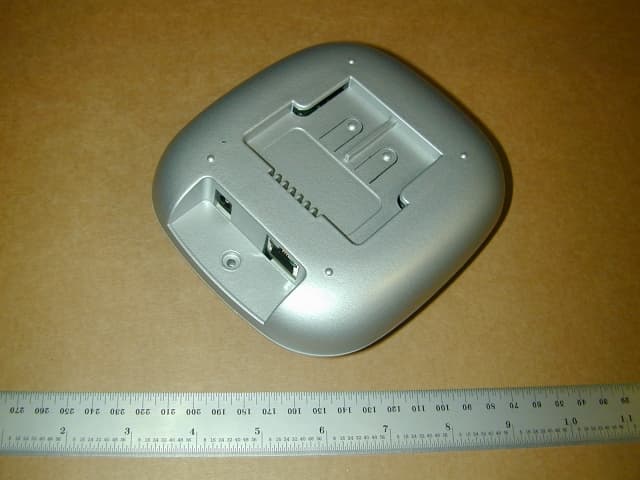
PEY13741
Jun 02, 2003950AP Bluetooth Device
Equipment Class
DSS - Part 15 Spread Spectrum Transmitter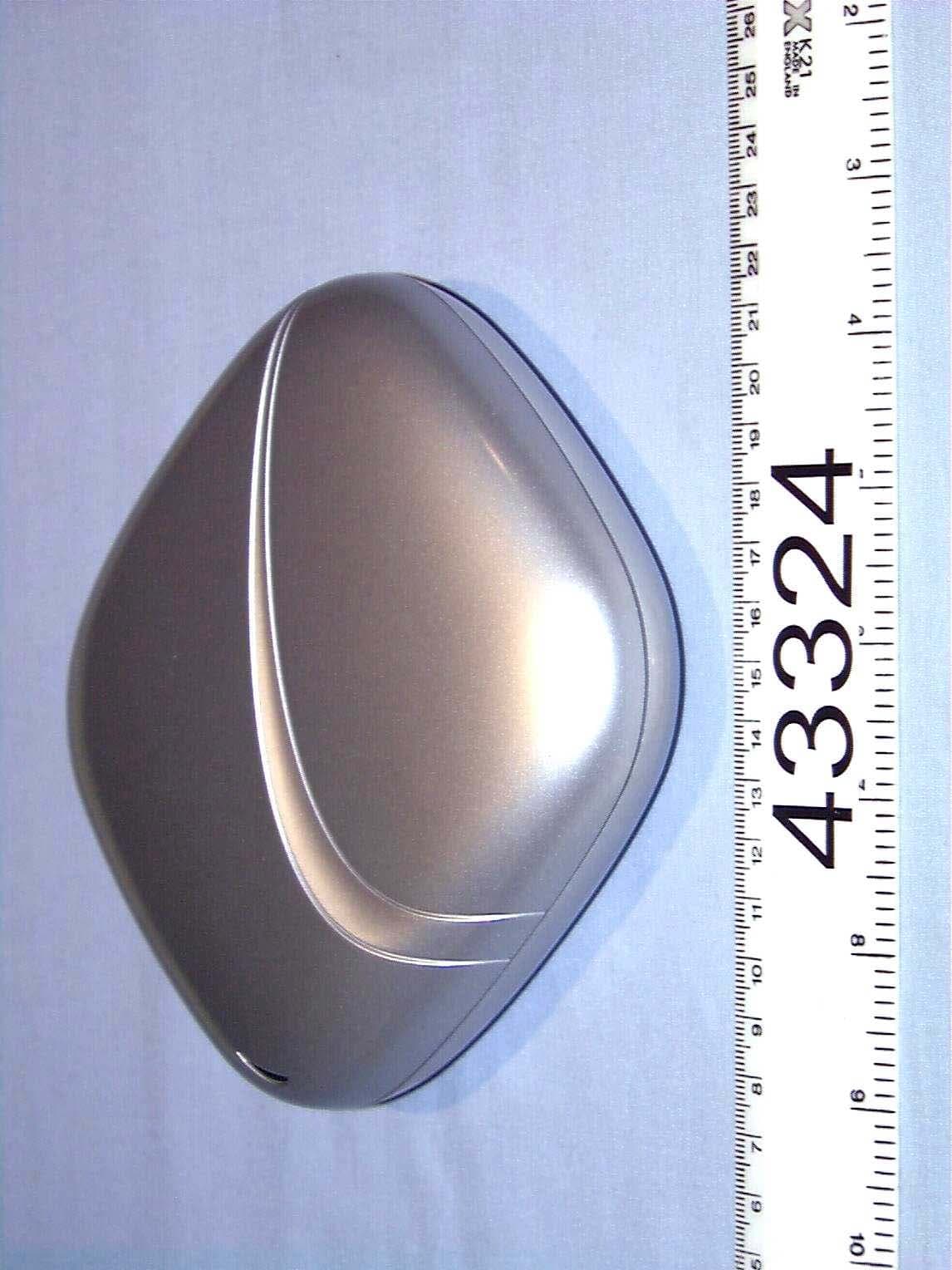
PEY1150AP
Jun 01, 2002Bluetooth Access Point
Equipment Class
DSS - Part 15 Spread Spectrum Transmitter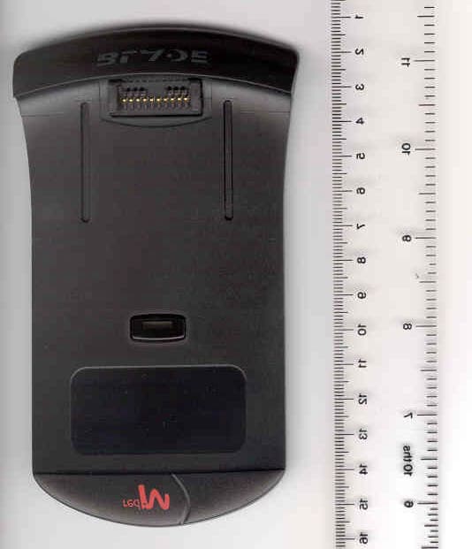
PEYBLADE1
Oct 03, 2001Bluetooth transmitter
Equipment Class
DSS - Part 15 Spread Spectrum Transmitter
PEY3000AS2
Jul 03, 2001Bluetooth Access Server
Equipment Class
DSS - Part 15 Spread Spectrum Transmitter
PEY3000AS
Mar 20, 2001Bluetooth Access Server
Equipment Class
DSS - Part 15 Spread Spectrum Transmitter