PEYBLADE1Bluetooth transmitter
Red-M (Communications) Limited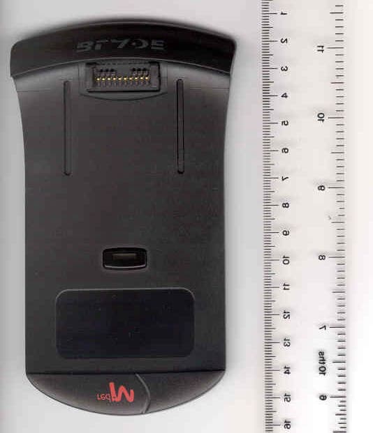
Click to zoom
Application Details
- Equipment Class
- DSS - Part 15 Spread Spectrum Transmitter
- Date of Grant
- Oct 03, 2001
- Application Purpose
- Original Equipment
- Date of Application
- Oct 03, 2001
- Equipment Note
- Bluetooth transmitter
- Frequency Range
- 2402.00000000 - 2480.00000000
- Country
- United Kingdom
Documents & Files
Document Text
Text extracted from the exhibit documents filed with the FCC. Open a document above to read the original.
Users Manual
980-959-03 Red-M Blade Bluetooth Clip-on for Palm Vx User Guide 2 Red-M Blade - Bluetooth Clip-on for Palm Vx Getting Started Guide 3 Table of contents Introduction ..............................................................................5 About the Red-M Blade ................................................................ 5 Getting started ........................................................................... 6 Red-M Blade overview ...............................................................7 Bluetooth services ....................................................................... 7 Additions to Palm Vx menus ......................................................... 7 Managing Bluetooth devices .......................................................... 8 Palm network service settings ....................................................... 9 Installing the Red-M Blade software .......................................11 Before you begin ....................................................................... 11 To install the Red-M Blade software ............................................. 11 Additional software on the Red-M Blade CD .................................. 11 Attaching the Red-M Blade ......................................................12 Detaching the Red-M Blade .....................................................13 Configuring a connection to the Internet via a mobile phone ..14 Before you begin ....................................................................... 14 To configure your Palm Vx to connect to a mobile phone ................ 19 Configuring a Bluetooth-enabled LAN connection....................21 Before you begin ....................................................................... 21 To configure your Palm Vx to connect to LAN Access infrastructure .. 21 Configuring Bluetooth HotSync operations ..............................23 Configuring a HotSync operation with a computer .......................... 23 Configuring a HotSync operation via a Bluetooth-enabled LAN ......... 25 Configuring a remote HotSync operation via a mobile phone ........... 27 Technical support and contact information..............................30 Regulatory information ...........................................................31 Europe (EEA) ............................................................................ 31 North America .......................................................................... 31 Power supply information ........................................................... 32 Red-M User License and Limited Warranty Agreement ............35 4 Red-M Blade - Bluetooth Clip-on for Palm Vx User Guide 5 Introduction About the Red-M Blade The Red-M Blade is a simple and innovative accessory that adds a new level of flexibility to your Palm TM Vx handheld. Whether you are in the office or on the road you can enjoy hassle-free, wireless connection to personal, corporate and public data. With a Red-M Blade and a Bluetooth TM enabled mobile phone, you can access the Internet, and send and receive email. The connection is cable-free and there is no longer any need to carefully line up your Palm Vx handheld with your mobile phone or PC to achieve a line-of-sight, infrared connection. You can perform a wireless HotSync ® operation to your laptop via your Red-M Blade instead of the usual Palm cradle. When away from the office, you can perform a remote HotSync operation via your mobile phone. The Red-M Blade also enables you to interact with other Bluetooth-enabled Palm Vx handhelds. If your office has Bluetooth infrastructure installed, you can use your Palm Vx with the Red-M Blade attached in meeting rooms and other Bluetooth enabled areas to maintain connection to the corporate intranet or Internet, to send and receive emails, and to update your calendar. 6 Getting started To use your Red-M Blade, do the following: 1. Install the software For instructions on how to install Red-M Blade software on your Palm Vx, see Installing the Red-M Blade software on page 11. 2. Attach the Red-M Blade For instructions on how to attach the Red-M Blade, see Attaching the Red-M Blade on page 12. 3. Configure your Palm Vx for Bluetooth services Configure the software to connect with any or all of the following Bluetooth-enabled devices: •a mobile phone for access to the Internet or to perform remote HotSync operations with your computer via your corporate network (where you have a remote access dial-up facility). For instructions, see Configuring a connection to the Internet via a mobile phone on page 14 and Configuring a remote HotSync operation via a mobile phone on page 27. •a laptop computer or PC to perform HotSync operations. For instructions, see Configuring a HotSync operation with a computer on page 23. •an Access Point on your local area network (LAN) for connection to LAN intranet and Internet services and to perform HotSync operations with a designated computer. For instructions, see Configuring a Bluetooth-enabled LAN connection on page 21 and Configuring a HotSync operation via a Bluetooth-enabled LAN on page 25. •another Bluetooth enabled Palm Vx handheld for playing games. There are games and associated documentation included on the Red-M CD. Red-M Blade - Bluetooth Clip-on for Palm Vx User Guide 7 Red-M Blade overview This section lists the Bluetooth services provided by the Red-M Blade. It describes the additional options and menu items that you will find on your Palm Vx handheld following installation of the Red-M Blade software. It also explains how to use device categories and the information used when you connect to the Internet. Bluetooth services To enable the Red-M Blade to connect to a number of different types of devices, Red-M software supports three Bluetooth services: •LAN Access Use this service to connect to Bluetooth network infrastructure. •Dial-up Networking Use this service to connect to a Bluetooth-enabled mobile phone. •Serial Use this se…
Text truncated - open the document above for the full version.
Cover Letter(s)
FCC ID: PEYBLADE1 Response to TCB findings Hi Mark, We have completed our review and identified the following issues: 1. We see the two bandedge plots in the test report but we do not appear to have the information necessary to convert them to field strength for comparison with the 15.209 limit. Please provide additional information about how to convert the high channel band edge plot to a field strength measurement or tell us where it is in the report. Response - attached is the user manual for the Palm Vx clip-on (Palmtext.pdf). The 15.19(a)(3) statement is on page 31, and the co-location warning statement has been added for future prints of the manual. To cover the co-location statement for the 1000 manuals we have already printed we are inserting a flyer into the relevant section of the manual. A copy of the flyer is also attached (98096801.pdf). Response - The attached pdf of a spreadsheet contains the 2.4835 GHz radiated band edge measurements and the measurements of the spectral power density in inquiry mode, for the Palm Vx clip-on. We have only measured the one acquisition mode (inquiry mode) as both acquisition modes will result in the same spectral power density. A rationale for that decision is below. Rationale. In 'normal' operation, the device transmits DH1 packets in alternate slots spread over 79 channels. Duty cycle is (30us unmodulated carrier + 366us packet) / (2*625) = 31.7% giving a channel occupancy of 31.7% / 79 = 0.4% ...or DH5 packets with 1 slave slot in between, spread over 79 channels: Duty cycle is (30us unmodulated carrier + 2870us packet) / (6*625) = 77.3% giving a channel occupancy of 77.3% / 79 = 0.98% In inquiry/page mode, the device transmits packets that contain only the access code, but twice in one normal slot time and only spread over 32 channels: Duty cycle is 2 * (30us unmodulated carrier + 68us packet) / (2*625) = 15.7% giving is channel occupancy of 15.7% / 32 = 0.49% Therefore the average amount of power in any given channel when performing an inquiry or a page cannot exceed the power realised in that channel when transmitting continuous DH5 packets with a normal hop sequence. Given that you have already done testing with DH5 packets [I assume], your current results ought to be applicable. There is one small caveate to this argument. In the case of paging or inquiry, the synthesiser is hopping more often and there are many more ramp up / ramp down sequences. We know that a large proportion of the in-band spurious is generated during ramp up/down, so higher levels of in-band spurious might be seen during page or inquiry than during continuous DH5 transmission. In practise, I don't think that this is a problem, since all in-band spurious will be below -30dBc and therefore not add significantly to the spectral density. Inquiry & page mode will result in the SAME spectral density - neither is worse than the other. The TCB should refer to PartB of the Bluetooth specification version 1.1, table 11.3. They will see that the hop selection scheme is the same for both page and inquiry. The modes differ only in the clock which determines the current point in the hop sequence and in the actual access code that is transmitted. The hop sequence itself and the packet timing is the same in both cases. 2. The manual needs to contain an RF exposure statement as follows - “IMPORTANT NOTE: To comply with FCC RF exposure compliance requirements, the following antenna installation and device operating configurations must be satisfied - The device and its antenna must not be co-located or operating in conjunction with any other antenna or transmitter.” 3. The 15.19(a)(3) statement is not on the label. For this application this statement can go in the manual. Response – see response to issue 1. 4. Please describe the antenna arrangement as it not obvious from the photos. Response - Palm Vx clip-on uses a 0 dBi RangeStar PCB antenna soldered directly to the main PCB of the product. Best regards Barry C. Quinlan Certification & Telecom Manager ------------------------------------------------------------------------------- Curtis-Straus LLC Voice: 978.486.8880 x270 527 Great Road Fax: 978.486.8828 Littleton, MA 01460 http://www.curtis-straus.com --------------------------------------------------------------------------------
ID Label/Location Info
Serial Number / Bluetooth Address: 000281 DDDDDE Assembly: 158-172-06 Made in the UK 1 5 8 - 1 8 5 - 0 7 © Red-M 2001. Patents Pending ARTWORK All detail within this box to be printed except that shown in RED. Any detail in GREEN to be printed but see notes for specific content. Notes: (1) Serial Numbers increment in steps of 1. Specific range of values will be specified with order. (2) Artwork to be made from CorelDraw (.CDR) format. PDF format for inspection only. (3) Barcode is format Code39 and comprises a Single Character Prefix as defined above followed by the right-hand 6 characters of “Serial No. / Bluetooth Addr” (eg “ZDDDDDE” where “Z” is the Single Character Prefix). Artwork - Red-M Rating Plate Label Bluetooth Clip-on for Palm Vx, CE + US/Canada/CSA + Bluetooth mark 158-185-07 158-131-01 Artwork Revision A RevDateBy 3/9/01NE Add FCC Logo (NB new FCC ID for Blade version). TITLE: USE BLANK STOCK: VERSION: ARTWORK/LABEL PART NUMBER: Red-M Wexham Springs Framewood Road Wexham Slough SL3 6PJ England Copyright 2001 Red-M© FCC ID: PEYBLADE1 Bluetooth Clip-on for Palm Vx Barcode Single Character Prefix is “I” Canada 3868 104415 A S a m p le L a b e l A r t w o r k f o r A p p r o v a ls A p p li c a t io n s
Operational Description
SiW1502 Data Sheet Preliminary Information November 3, 2000 60 0010 R00B SiW1502 DS Page 1 of 21Silicon Wave, Inc. SiW1502 Radio Modem IC 1. INTRODUCTION The SiW1502 Radio Modem IC is part of Silicon Wave's Odyssey™ solutions for Bluetooth™ wireless communications. The SiW1502 IC combines a 2.4-GHz radio transceiver and GFSK modem with digital control functions meeting Bluetooth specifications. The SiW1502 IC is designed to work with the Silicon Wave SiW1601 Link Controller IC or other compatible IC to enable production of Bluetooth wireless communication products. 2. FEATURES • Radio and modem with combined RF analog and digital CMOS circuits on a single integrated silicon chip. • Fully compliant with Bluetooth Specification 1.0 B. • Pin-to-pin compatibility with the SiW1501. • Direct-conversion radio architecture with integrated VCO and frequency synthesizer requiring minimal external components. • Integrated analog-digital conversion circuits transform I/O signals between the radio and GFSK modem. • Integrated GFSK modem with digital modulation, channel filtering, AFC, symbol timing recovery, and bit slicer. • Integrated 0 dBm transmit driver with eight output power levels. • Direct interface to Bluetooth controller ICs through a low pin-count, digital interface. • Optimized design for low power consumption, low cost, and small size. 3. APPLICATIONS The SiW1502 Radio Modem is suitable for all applications requiring a Bluetooth-compliant radio link in a low-power and cost-effective implementation. • Cellular Use: mobile phone handset integration and accessories. • Office: office PCs, notebook PCs, and laser printer interconnection. • Personal Data: PDA, palmtop, and personal organizer communications. • Consumer: digital cameras, handheld game units. • Automotive: hands-free car kit. Radio Modem ICSiW1502 Data Sheet Preliminary Information November 3, 2000 60 0010 R00B SiW1502 DS Page 2 of 21Silicon Wave, Inc. 4. DESCRIPTION Figure 1 shows the functional block diagram. During the receive process, the radio signal is taken from a pair of balanced RF I/O pins that feed into the low noise amplifier (LNA). Direct I/Q down conversion and on-chip filtering send the processed I/Q data to the analog-to-digital converter before processing by the GFSK demodulator. Within the demodulator, data detection and timing recovery circuits convert the data for transfer to an external device. The transmit process operates in a similar fashion in reverse order. Digital control functions and a programming interface provide radio modem control and a flexible interface to external Bluetooth link controller ICs. For efficient power management, each section of the radio may be powered down when not in use. The active circuitry required for the master clock reference and low-power clock used to supply clock signals to external devices is located on the SiW1502. The transmitted signal is GFSK modulated data that is amplified on the chip to yield a radiated output of 0 dBm. A power control signal for an external amplifier is provided. EXT_PA_CNTL System Control Logic MODEM_TX_DATA MODEM_RX/TX_DATA MODEM_CD/TXEN MODEM_RX_CLK Baseband Interface RF Interface RF_IN/OUT+ RF_IN/OUT- TX_RX_SW ITCH /RESET_RM ENABLE_RM HOP_STRB Clock Generation and Distribution 32KHZ_CLK BB_CLK 32MHZ_XTL 32KHZ_XTL BB_CLK_MODE Data SPI_TXD SPI_CLK /SPI_SS SPI_RXD Serial Program ming Interface (SPI) Register File GFSK MODEM LNA ADC ADC Driver VCO/ PLL PWR CNTL DAC DAC 0 90 0 90 Control Control Figure 1: SiW1502 IC Block Diagram Radio Modem ICSiW1502 Data Sheet Preliminary Information November 3, 2000 60 0010 R00B SiW1502 DS Page 3 of 21Silicon Wave, Inc. 5. PIN DESCRIPTION The SiW1502 IC’s radio and modem interface, the Serial Programming Interface (SPI), and the two clock inputs are required for proper operation. 5.1. Radio Interface The radio interface provides an antenna connection through external circuitry to transmit and receive the Bluetooth radio signals. Control signals for the external transmit/receive switch and optional power amplifier are available. NOTE: The RF signals occupy special pin locations on the device package. For an example, please refer to the application circuit in Section 8 on page 15. External impedance matching and balun circuits are required to complete the interface to the antenna. Please refer to Figure 10 in Section 8 for the recommended external circuit details. NameDirectionDescription RF_IN/OUT+I/OPositive RF input and output pin. RF_IN/OUT-I/ONegative RF input and output pin. EXT_PA_CNTLO Power control to external power amplifier. This output provides a variable current source that can be used to control the external power amp. TX_RX_SWITCHO Output to select external transmit/receive switch circuit for external PA (20 dBm) configurations. High = Receive Low = Transmit Table 1: Signal Description 5.2. Modem Interface The modem interface transfers the Bluetooth data between the SiW1502 and an external controller such as the SiW1601 IC. The programmable interface on the SiW1502 can be set to various operating modes, depending on the desired interface usage. Programming of the interface is done through internal registers. For reference purposes, Table 2 provides a brief description of typical interface modes. NameDirectionDescription MODEM_TX_DATAITransmit Data. MODEM_RX_DATAI/O This pin has three possible programmable mode settings (through internal registers): 1. Symbol synchronized received data at 1 MHz. 2. Sliced receive data at 8 MHz (sliced output). 3. Both transmit and receive data for low pin-count mode. MODEM_CD/TXENI/ODual function carrier detect and transmit enable. This bi-directional signal can be enabled through internal registers. During transmit, this pin can be used as an INPUT to indicate valid transmit data (TXEN). During receive, this pin can be used as OUTPUT to indicate carrier detect (CD). Table 2: Modem Interface Signal Description Radio Modem ICSiW1502 Data Sheet Preliminary Informat…
Text truncated - open the document above for the full version.
Operational Description
SiW1602 Data Sheet Preliminary Information February 5, 2001 60 0009 R00C SiW1602 IC DS Page 1 of 14Silicon Wave, Inc. SiW1602 Link Controller IC 1. INTRODUCTION The Odyssey™ SiW1602 Link Controller IC is part of Silicon Wave's solutions for Bluetooth™ wireless communications. The SiW1602 provides the Bluetooth link management and control functions in a digital ASIC. Combined with the SiW1502 Radio Modem IC, it provides a complete and cost effective hardware solution to integrate into products. Bus Interface Unit Link Controller State Machine and Control Registers Power Management/ Interrupt Controller and System reset MODEM Interface A0 to A9 D0 to D7 /CS /WR /RD /WAIT /INT0 /INT1 WAKEUP MCU_WAKEUP /PWR_RESET /MANUAL_RESET /DISABLE LOWPWR_EN FECScramble CRC HEC TX FIFO FEC De- scramble CRC HEC RX FIFO USB Interface /USB_CS GPO1 /USB_ INT PLL Serial Programming Interface (SPI) Clock Generation and Distribution BB_CLK 32KHZ_CLK BAUD_CLK MCU_CLK /SPI_SS SPI_CLK SPI_TXD SPI_RXD USB_ D+USB_ D- GPO2 ENABLE_RM /RESET_OUT HOP_STRB MODEM_TX_DATA MODEM_RX/TX_DATA MODEM_CD/TXEN MODEM_RX_CLK Figure 1: SiW1602 Link Controller IC Functional Block Diagram 2. FEATURES • Direct interface to SiW1502 Radio Modem. • USB (compliant to specification v1.1) interface to host computer system. • Link control function implemented in hardware compliant to Bluetooth specification 1.1. • Support for all Bluetooth packet types. • ACL and SCO connections at full speed of 1 Mbit/s. • Piconet functions, including master/slave switch capabilities. • Authentication and encryption as defined in the specification. • Dual on-chip 384-byte transmit and receive FIFOs ensure packet data is never lost due to interrupt latency. • Programmable interrupt controller. • Time-critical packet processing. • Low-power modes such as sniff, hold and park. • Support for transmit power control and receiver RSSI functions. • Available in 108-pin fine-pitch BGA flip chip package. Link Controller ICSiW1602 Data Sheet Preliminary Information February 5, 2001 60 0009 R00C SiW1602 IC DS Page 2 of 14Silicon Wave, Inc. 3. APPLICATIONS The SiW1602 is suitable for all applications requiring packet processing and link management for Bluetooth communications. When combined with the SiW1502 Radio Modem IC, a low power and cost effective solution can be implemented. • Bluetooth access points. • Cellular telephones. • Desktop and notebook PCs and accessories. • Printers. • PDAs (personal digital assistant) and palmtops. A typical design of a Bluetooth compliant product consists of the SiW1502 Radio Modem and the SiW1602 Link Controller along with the Hitachi H8S/2238 or H8S/2214 processor. This example illustrates the connection flow between the system’s main components for USB applications: FEC De- scramble CRC HEC RX FIFO Bus Interface Unit Link Controller State Machine and Control Registers FEC Scramble CRC HEC TX FIFO Power Management/Interrupt Controller and System Reset MODEM Interface Silicon Wave SiW1502 Radio Modem Hitachi H8S/2238 or H8S/2214 MCU_CLK V2.3_OUT BAUD_CLK Universal Serial Bus Device Controller and Transceiver USB_D+ USB_D- LOWPWR_EN /DISABLE /PWR_RESET External Voltage Regulator & Low Power Logic 3V_D 3V_A VDD Clock Generation and Distribution SPI Interface A0 to A9 D0 to D7 /CS /WR /RD /WAIT /INT0 /INT1 WAKEUP SYSTEM_WAKEUP /USB_CS /USB_INT ENABLE_RM /RESET_OUT HOP_STRB MODEM_TX_DATA MODEM_RX/TX_DATA MODEM_CD/TXEN MODEM_RX_CLK BB_CLK 32KHZ_CLK /SPI_SS SPI_CLK SPI_TXD SPI_RXD Figure 2: Typical SiW1602 Implementation UART applications are also possible using the same system components. The UART signals can drive the serial interface on the Hitachi H8S directly. In this case, the USB functionality of the SiW1602 can be turned off. Link Controller ICSiW1602 Data Sheet Preliminary Information February 5, 2001 60 0009 R00C SiW1602 IC DS Page 3 of 14Silicon Wave, Inc. 4. LINK CONTROLLER DESCRIPTION The link controller hardware in the SiW1602 implements all the real-time, lower-layer protocol processing. This hardware performs the logical protocol processing within the unit that enables the host to communicate over a Bluetooth link. Real-time functions such as frequency hopping, burst timing, synthesizer programming, and clock synchronization are implemented in hardware. Also incorporated within the SiW1602 logic is power management and clock distribution. In addition to the radio control functions described above, the SiW1602 processes Bluetooth transmit and receive data as described below in sections 4.1 through 4.7. 4.1. FEC: Forward Error Correction FEC corrects errors, which might have occurred during the transmission or receipt of the original data. FEC correction rates at 1/3 and 2/3 are implemented. 4.2. Whiten/De-whiten: Scramble/Unscramble Whiten/Scramble refers to the process of randomizing transmitted data to avoid any undesirable DC bias effects that might result from long strings of 1’s or 0’s in data packets. De-whiten/Unscramble is the reversal of the original process where the original data can be extracted. 4.3. Encrypt/Decrypt: Apply/Remove Encryption Encryption is the security feature where keys are used to prevent unauthorized access to data. This functional block is responsible for the processing of authentication and essential management functions required for Bluetooth communications. 4.4. CRC: Cyclic Redundancy Check This is the error detection function implemented to process the CRC field within the payload section of a Bluetooth transfer packet. On the receive side, the CRC is checked with the expected value based on Bluetooth specified algorithms. Prior to transmit, a proper CRC is generated and appended to the payload. 4.5. HEC: Header Error Correction This is the error correction function for the 8-bit HEC field of the Bluetooth packet header as described in the Bluetooth specification 1.1. 4.6. Rx Buffers: Storage for Received Packets The FIFO buffer is 384 bytes in length. This functional block contains the ac…
Text truncated - open the document above for the full version.
RF Exposure Info
Red-M Wexham Springs . Framewood . Framewood Road . Wexham . Slough . SL3 6PJ Tel: +44 (0)1753 661700 Fax: +44 (0)1753 661745 www.red-m.com Red-M (Communications) Limited trading as Red-M . Registered Office as above Company Registered in England . Registered No: 3985301 . VAT No: GB 669 1783 84 Maximum Permissable Exposure Calculations. The following calculations are based on guidelines published in OET Bulletin 65, Edition 97-01, August 1997: Evaluating Compliance with FCC Guidelines for Human Exposure to Radiofrequency Electromagnetic Fields. Near to Far Field Frequency (GHz)Wavelength (m)Transition (cm) Lower2.40000.125~2.0 Upper2.48350.121~1.9 For a simple case, discounting reflections, equation 4, page 19 gives: Power Density, S= PG/ 4πR² Worst case power input to antenna :-1.3 dBm Worst case power input to antenna :0.74 mW. Antenna gain :0 dBi. Numeric antenna gain :1. General population/ uncontrolled limit:1mW/cm². Distance from antenna, R, where power density limit is reached is: R= √ (PG/ 4πS) R= 0.2 cm Notes. 1. The general population/ uncontrolled limit is taken from OET 65, Appendix A Table 1B page 67. Red-M Wexham Springs . Framewood . Framewood Road . Wexham . Slough . SL3 6PJ Tel: +44 (0)1753 661700 Fax: +44 (0)1753 661745 www.red-m.com Red-M (Communications) Limited trading as Red-M . Registered Office as above Company Registered in England . Registered No: 3985301 . VAT No: GB 669 1783 84 For a worst case prediction of power density, including reflections from nearby surfaces, OET 65 recommends using equation 6, page 20. Power Density S= PG/πR² Using the same figures as above the distance from antenna, R, where power density limit is reached is: R= √ PG/ πS R= 0.5 cm. Mark Bailey 20/03/01 Red-M Ltd.
Test Report
Radio Frequency Investigation Ltd, Ewhurst Park, Ramsdell, Basingstoke, Hampshire, RG26 5RQ, ENGLAND. Tel: +44 (0) 1256 851193 Fax: +44 (0) 1256 851192 Registered in England, No. 211 7901. Registered Office: Ewhurst Park, Ramsdell, Basingstoke, Hampshire RG26 5RQ TESTING 0644 TEST REPORT FROM RADIO FREQUENCY INVESTIGATION LTD. Test Of: Red-M (Communications) Ltd. Bluetooth Clip-On For Palm Vx (code no. 0400-001) To: F.C.C. Part 15 Subpart C: 2000 (Intentional Radiators) Section 15.247 Test Report Serial No: RFI/EMCB1/RP42145B This Test Report Is Issued Under The Authority Of Richard Jacklin, Operations Director: Checked By: Tested By:Release Version No: PDF01 Issue Date: 05 June 2001Test Dates: 30 April 2001 to 2 March 2001 This report is issued in Adobe Acrobat portable document format (PDF). It is only a valid copy of the report if it is being viewed in PDF format with the following security options not allowed: Changing the document, Selecting text and graphics, Adding or changing notes and form fields. Furthermore, the date of creation must match the issue date stated above. This report may be copied in full. RADIO FREQUENCY INVESTIGATION LTD.TEST REPORT S.No: RFI/EMCB1/RP42145B EMC DepartmentPage 2 of 52 Issue Date: 05 June 2001 Test Of:Red-M (Communications) Ltd. Bluetooth Clip-On For Palm Vx (code no. 0400-001) To:F.C.C. Part 15 Subpart C: 1998 (Intentional Radiators) Section 15.247 This page has been left intentionally blank. RADIO FREQUENCY INVESTIGATION LTD.TEST REPORT S.No: RFI/EMCB1/RP42145B EMC DepartmentPage 3 of 52 Issue Date: 05 June 2001 Test Of:Red-M (Communications) Ltd. Bluetooth Clip-On For Palm Vx (code no. 0400-001) To:F.C.C. Part 15 Subpart C: 1998 (Intentional Radiators) Section 15.247 Table of Contents 1. Client Information..............................................................................................................4 2. Equipment Under Test (EUT)...........................................................................................5 3. Test Specification, Methods And Procedures.............................................................10 4. Deviations From The Test Specification.......................................................................12 5. Operation Of The EUT During Testing..........................................................................13 6. Summary Of Test Results...............................................................................................14 7. Measurements, Examinations And Derived Results...................................................15 8. Measurement Uncertainty...............................................................................................29 Appendix 1. Test Equipment Used.....................................................................................30 Appendix 2. Measurement Methods...................................................................................31 Appendix 3. Test Configuration Drawings.........................................................................41 Appendix 4. Graphical Test Results...................................................................................46 Appendix 5. Photographs of EUT.......................................................................................51 RADIO FREQUENCY INVESTIGATION LTD.TEST REPORT S.No: RFI/EMCB1/RP42145B EMC DepartmentPage 4 of 52 Issue Date: 05 June 2001 Test Of:Red-M (Communications) Ltd. Bluetooth Clip-On For Palm Vx (code no. 0400-001) To:F.C.C. Part 15 Subpart C: 1998 (Intentional Radiators) Section 15.247 1. Client Information Company Name: Red-M (Communications) Ltd. Address: Wexham Springs Framewood Road Wexham Slough SL3 6PJ. Contact Name: Mark Bailey. RADIO FREQUENCY INVESTIGATION LTD.TEST REPORT S.No: RFI/EMCB1/RP42145B EMC DepartmentPage 5 of 52 Issue Date: 05 June 2001 Test Of:Red-M (Communications) Ltd. Bluetooth Clip-On For Palm Vx (code no. 0400-001) To:F.C.C. Part 15 Subpart C: 1998 (Intentional Radiators) Section 15.247 2. Equipment Under Test (EUT) The following information (with the exception of the Date of Receipt) has been supplied by the client: 2.1. Identification Of Equipment Under Test (EUT) Brand Name:Red-M Model Name or Number:Bluetooth Clip-On For Palm Vx (code no. 0400-001) Unique Type Identification:0400-001 Serial Number:020 Country of Manufacture:UK FCC ID Number:Not applicable Date of Receipt:30 April 2001 2.2. Description Of EUT The equipment under test is a clip-on Bluetooth module for Palm Vx personal digital assistants (PDAs). 2.3. Modifications Incorporated In EUT The EUT has not been modified from what is described by the Model Name and Unique Type Identification stated above…
Text truncated - open the document above for the full version.
Contact Information
Applicant
Mark Bailey(Senior Approvals Engineer)
Test Firm
BSI Product ServicesDaniel Griffin
Technical Specifications
| # | Rule Parts | Frequency Range | Power Output |
|---|---|---|---|
| 1 | 15C | 2.40 GHz - 2.48 GHz | 740.00 µW |
Other Applications from Red-M (Communications) Limited
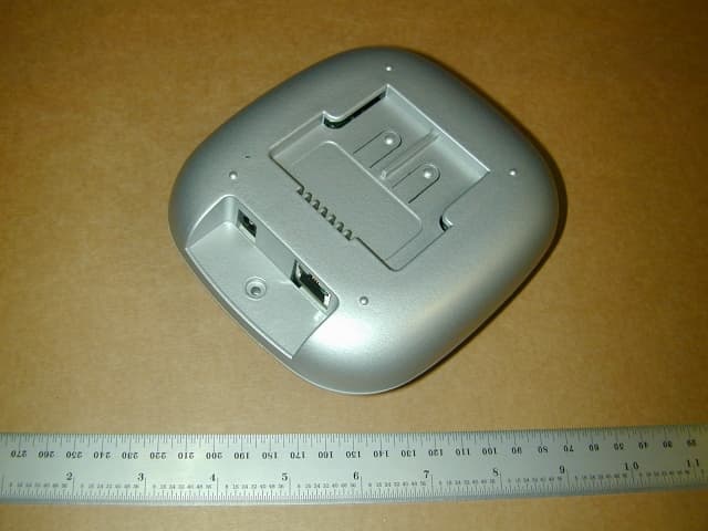
PEY13741
Jun 02, 2003950AP Bluetooth Device
Equipment Class
DSS - Part 15 Spread Spectrum Transmitter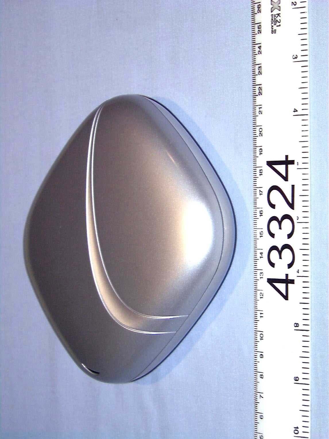
PEY1150AP
Jun 01, 2002Bluetooth Access Point
Equipment Class
DSS - Part 15 Spread Spectrum Transmitter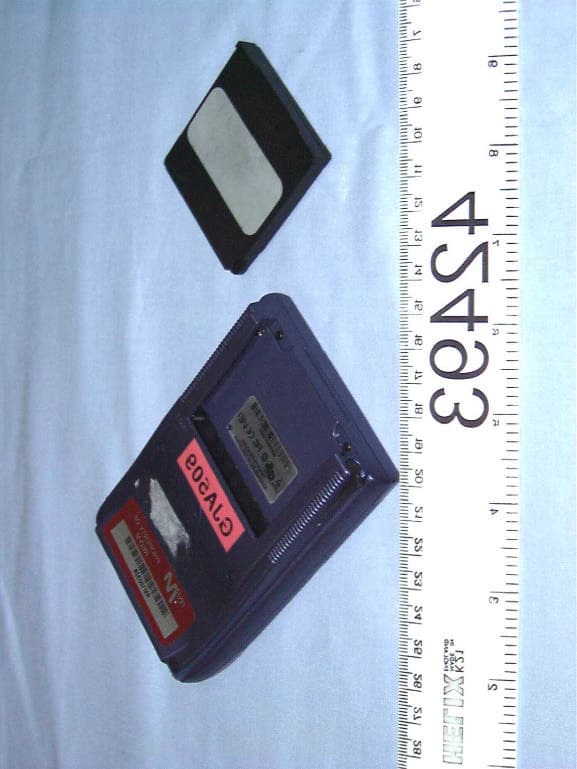
PEYBLADE2
Nov 12, 2001Bluetooth transmitter
Equipment Class
DSS - Part 15 Spread Spectrum Transmitter
PEY3000AS2
Jul 03, 2001Bluetooth Access Server
Equipment Class
DSS - Part 15 Spread Spectrum Transmitter
PEY3000AS
Mar 20, 2001Bluetooth Access Server
Equipment Class
DSS - Part 15 Spread Spectrum Transmitter