PGCAD-1310ADI ADSL Modem
UAT Inc.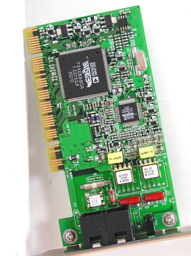
Click to zoom
Application Details
- Equipment Class
- JBP - Part 15 Class B Computing Device Peripheral
- Date of Grant
- Nov 29, 2001
- Application Purpose
- Original Equipment
- Date of Application
- Nov 29, 2001
- Equipment Note
- ADI ADSL Modem
- Company
- UAT Inc.
- Country
- Taiwan
Documents & Files
Document Text
Text extracted from the exhibit documents filed with the FCC. Open a document above to read the original.
Users Manual
a Analog Devices Canada Ltd. 777 Bay Street, Suite 2303 Toronto, Ontario CANADA M5G 2C8 Voice: (416) 59x-3200 Fax: (416) 59x-4004 ADSL PCI NIC User Manual Document Number 20-23000-100 Revision 1.3 01-05-25 This document contains confidential information and is proprietary to Analog Devices Inc. No part of this document may be reproduced in any form or by any means without the prior permission of Analog Devices Inc. All specifications are subject to change without notice. Federal Communications Commission (FCC) Requirements, Part 15 This equipment has been tested and found to comply with the limits for a class B digital device, pursuant to part 15 of the FCC Rules. These limits are designed to provide reasonable protection against harmful interference in a residential installation. This equipment generates, uses and can radiate radio frequency energy and, if not installed and used in accordance with the instructions, may cause harmful interference to radio communications. However, there is no guarantee that interference will not occur in a particular installation. If this equipment does cause harmful interference to radio or television reception, which can be determined by turning the equipment off and on, the user is encouraged to try to correct the interference by one or more of the following measures: ---Reorient or relocate the receiving antenna. ---Increase the separation between the equipment and receiver. ---Connect the equipment into an outlet on a circuit different from that to which the receiver is connected. ---Consult the dealer or an experienced radio/TV technician for help. CAUTION: Any changes of modifications not expressly approved by the grantee of this device could void the users authority to operate the equipment. ADSL PCI NIC User Manual Rev 1.3 05/25/01 Analog Devices Proprietary Page 2 Table of Contents WELCOME TO ADI ADSL PCI NIC !.................................................................................................3 DOCUMENT ANNOTATIONS.............................................................................................................3 SYSTEM REQUIREMENTS.................................................................................................................3 HARDWARE INSTALLATION............................................................................................................4 FAMILIARIZING YOURSELF WITH YOUR ADSL BOARD..............................................................................4 INSTALLING THE ADSL BOARD..............................................................................................................4 SOFTWARE INSTALLATION.............................................................................................................5 PPPOE (RFC1483) DRIVER INSTALLATION FOR WINDOWS 9X.................................................................6 Device Driver Installation.................................................................................................................6 GUI Configuration..........................................................................................................................10 Verify the modem.............................................................................................................................14 Uninstall the device driver..............................................................................................................18 PPPOA (RFC2364) DRIVER INSTALLATION FOR WINDOWS 9X...............................................................19 Device Driver Installation...............................................................................................................19 GUI Configuration..........................................................................................................................25 Verify the modem.............................................................................................................................29 Uninstall the device driver..............................................................................................................32 Setup a Connection..........................................................................................................................33 Make a Call.....................................................................................................................................35 CO BOARD...........................................................................................................................................37 PPPOE (RFC1483) CO DRIVER INSTALLATION.....................................................................................37 PPPOA (RFC2364) CO DRIVER INSTALLATION FOR WINDOWS NT4......................................................38 Install the ADSL PCI NIC card, RAS and related services...............................................................38 Setting registry................................................................................................................................43 Creating new user(s) for server side.................................................................................................43 Starting server.................................................................................................................................44 Create an entry in phone book on the client side.............................................................................46 UTILITY PROGRAMS........................................................................................................................50 TROUBLESHOOTING........................................................................................................................51 CHECKLIST..........................................................................................................................................51 ORDERING INFORMATION...........................................................…
Text truncated - open the document above for the full version.
Block Diagram
5 5 4 4 3 3 2 2 1 1 DD CC BB AA HYBRIDAFE CHIP AD6480 DIGITAL CHIP DSP AD6483 5VTO2.5V CONVERTER AS1119-2.5 PCI BUSXTAL 12MHZ VCXO 35.328 5V EEPROM 93C57 5VTO3.3V CONVERTER AS1119-3.5 POWER & GROUND 02 AD-1310 B 88Wednesday, October 31, 2001 Title SizeDocument NumberRev Date:Sheetof UAT Inc.
ID Label/Location Info
LABEL Format: This device complies with Part 15 of the FCC Rules Operation is subject to the following two conditions: (1) This device may not cause harmful interference, and (2) This device must accept any interference received, including interference that may cause undesired operation Model No.:AD-1310 FCC ID:PGCAD-1310 LABEL Size: 45 x 30 mm LABEL Position:
Test Report
Test Report ------------------------------------------------------------------------------- 2/16 Report No.: U1215786 Training Research Co., Ltd., TEL: 886-2-26935155, Fax: 886-2-26934440 Contents CHAPTER 1 INTRODUCTION......................................................................3 Description of EUT.......................................................................................3 Connections of EUT.....................................................................................3 Test method..................................................................................................3 Configuration of Test Setup..........................................................................4 Connections of Support Equipment..............................................................5 Connections of EUT.....................................................................................5 List of Support Equipment............................................................................6 CHAPTER 2 CONDUCTED EMISSION TEST..................................................9 Test condition and setup...............................................................................9 List of test Instrument...................................................................................9 Conducted Test Placement: (Photographs).................................................10 CHAPTER 3 RADIATED EMISSION TEST...................................................11 Test condition and setup.............................................................................11 List of test Instrument.................................................................................12 Radiated Test Placement: (Photographs)....................................................13 APPENDIX A..............................................................................................14 Conducted Emission Test Result................................................................14 APPENDIX B..............................................................................................15 Radiated Emission Test Result (Horizontal)..............................................15 Radiated Emission Test Result (Vertical)...................................................16 Test Report ------------------------------------------------------------------------------- 3/16 Report No.: U1215786 Training Research Co., Ltd., TEL: 886-2-26935155, Fax: 886-2-26934440 Chapter 1 Introduction Description of EUT This device is the modem of ADSL interface. The EUT is designed to install in the personal computer, It is a data transmission / receiving facility and makes your data equipment available to transmit / receive data via the EUT. Connections of EUT (1) Install the EUT into a personal computer’s PCI interface and screw it. (2) The Line jack is connected with a line cable to the ADSL evaluation module, which located remotely. (3) The Phone jack is connected with a telephone set. Test method The applicant provides the testing program. Pretest was found that the emission of operating mode is worse than standby mode. So, The final test is made at the operating mode. When the measurement was taken, the EUT was operated at “transmitting” and “receiving” mode simultaneously. While testing, the transmitting rate was set to “AUTO” which means it transmitted the test file depending on the telephone line condition, normally the operating rate is the highest speed. The test placement as the photographs showed is the worst case emission placed. (If the emission is close to the ambient, the resolution BW and view resolution will be reduced and the data will be recorded by detection of maximum hold peak mode.) The testing configuration of test setup is showing in the next page. Test Report ------------------------------------------------------------------------------- 4/16 Report No.: U1215786 Training Research Co., Ltd., TEL: 886-2-26935155, Fax: 886-2-26934440 Configuration of Test Setup USB Joystick EUT Mouse Keyboard Monitor Modem Printer PC To Far-end ADSL Evaluation Module Power USB Mouse Telephone Test Report ------------------------------------------------------------------------------- 5/16 Report No.: U1215786 Training Research Co., Ltd., TEL: 886-2-26935155, Fax: 886-2-26934440 Connections of Support Equipment PC: *Serial port --- an external modem *Printer port --- a printer *Monitor port --- a monitor *Keyboard port --- a keyboard *Mouse port --- a mouse *USB A port --- a USB mouse *USB B port --- a USB joystick (Each port on PC is connected with suitable device) Connections of EUT ADSL Modem: *Line jack --- 15m long, non-shielded, no ferrite bead, RJ-11 cable *Phone jack --- 7feet long, non-shielded, no ferrite core, RJ-11 cable Test Report ------------------------------------------------------------------------------- 6/16 Report No.: U1215786 Training Research Co., Ltd., TEL: 886-2-26935155, Fax: 886-2-26934440 List of Support Equipment PC:HP Brio 85xx 6/350 Model No.:D6928A Serial No. :SG91801432 FCC ID:N/A (Doc Approved) :3872H013 Power type:100 ~ 230VAC / 50 ~ 60Hz, 5A, Switching Power cord :Non-shielded, 2.33m long, Plastic, No ferrite core Monitor :HP 15’ Color Monitor Model No.:D2827A Serial No.:KR91161719 FCC ID:C5F7NFCMC1518X :3872B039 Power type:110 ~ 240 VAC / 50 ~ 60 Hz, Switching Power cord:Shielded, 1.83m long, No ferrite core Data cable :Shielded, 1.46m long, with two ferrite cores Keyboard:HP Model No.:SK-2501K Serial No.:MR80700789 FCC ID:GYUR38SK :3862A621 Power type:By PC Data cable :Shielded, 1.73m long, with ferrite core Mouse:HP Model No.:M-S34 Serial No.:LZB90714106 FCC ID:DZL211029 :4862A011 Power type:By PC Power cord:Non-shielded, 1.88m long, No ferrite core Test Report ------------------------------------------------------------------------------- 7/16 Report No.: U1215786 Training Research Co., Ltd., TEL: 886-2-26935155, Fax: 886-2-26934440 Modem:ACEEX Model No.:XDM41414 Serial No.:9641…
Text truncated - open the document above for the full version.
Test Setup Photos
Test Report ------------------------------------------------------------------------------- 10/16 Report No.: U1215786 Training Research Co., Ltd., TEL: 886-2-26935155, Fax: 886-2-26934440 Conducted Test Placement: (Photographs)
Test Setup Photos
Test Report ------------------------------------------------------------------------------- 13/16 Report No.: U1215786 Training Research Co., Ltd., TEL: 886-2-26935155, Fax: 886-2-26934440 Radiated Test Placement: (Photographs)
Contact Information
Applicant
Tom Chen(Manager, R & D)
Test Firm
Training Research Co., Ltd.Jack Tsai
Technical Specifications
| # | Rule Parts | Frequency Range | Power Output |
|---|---|---|---|
| 1 | 15B | - | - |
Other Applications from UAT Inc.
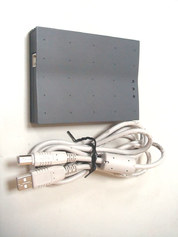
PGCWL-2111
Dec 13, 2001Wireless LAN USB Adaptor
Equipment Class
DTS - Digital Transmission System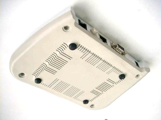
PGCAR-1150
Oct 10, 2001ADSL Router
Equipment Class
JBP - Part 15 Class B Computing Device Peripheral
PGCWL-3111
Sep 11, 2001Wireless Access Point
Equipment Class
DTS - Digital Transmission System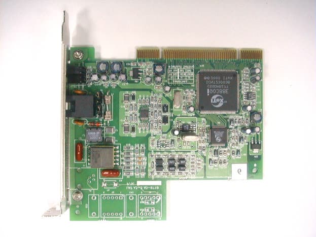
PGCAD-9711
Apr 16, 2001ADSL Add-on Card
Equipment Class
JBP - Part 15 Class B Computing Device Peripheral
PGCAD-1130
Apr 16, 2001ADSL Modem with USB Interface
Equipment Class
JBP - Part 15 Class B Computing Device Peripheral