PGCAR-1150ADSL Router
UAT Inc.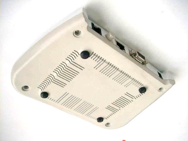
Click to zoom
Application Details
- Equipment Class
- JBP - Part 15 Class B Computing Device Peripheral
- Date of Grant
- Oct 10, 2001
- Application Purpose
- Original Equipment
- Date of Application
- Oct 10, 2001
- Equipment Note
- ADSL Router
- Company
- UAT Inc.
- Country
- Taiwan
Documents & Files
Document Text
Text extracted from the exhibit documents filed with the FCC. Open a document above to read the original.
Users Manual
EXHIBIT C User Manual ADSL Router AR-1150 User Manual v. 1.0 ADSL Router AR-1150 User Manual 1 Copyright Copyright © 2001, All rights reserved. This manual and software described in it are copyrighted with all rights reserved. This manual may not be copied, in whole or in part, without written consent. All product names are trademarks and or registered trademarks of their respective companies. ADSL Router AR-1150 User Manual 2 Environmental Requirements w Operating Temperature: 0º C to 55º C with airflow w Non-operating Temperature: -10º C to 85º C w Operating Humidity: 10% to 90% non-condensing w Non-operating storage humidity: 5% to 95% non-condensing Power Requirements w Input: 100-240V 0.3A 50-60Hz w Output: +5V 1.4A Connector Pin-out The ADSL modem card is equipped with a RJ-11 jack for connection to the ADSL data Port. The center two pins, pins 3 and 4, are used for ADSL data. For the card to make a proper ADSL connection, the installed ADSL data port should also use pins 3 and 4 for data. If the ADSL data port installation uses pins 2 and 5 for data, then a wiring converter will be required. Do not alter or remove the wiring converter if present. Consult with your ADSL provider before attempting any wiring changes. 2 3 4 5 ADSL Router AR-1150 User Manual 3 About This Manual This manual provides a comprehensive user’s guide and installation manual for Multi-mode ADSL Router. It has been organized in such a way to make it easy to follow by users worldwide. In the manual, there are many examples given in the commands, largely IP addresses and other values. Please realize that these are for example only and you must use the values provided by your ADSL service provider to achieve a connection. In order to ensure optimal comprehension, the following list provides brief descriptions of the formatting styles used throughout this manual. Commands: Commands are always referred to by using the words “type” or “click” before them. These commands are always shown as bold-faced words. For example, click Next, click OK, or type: command. Names of Windows (Dialog Boxes): The names of the windows (also referred to as dialog boxes) that appear on the PC screen are always referred to in quotes. For example, the “Setup Complete” window. Names of Options in Windows: The names of options to choose from inside the windows that appear on the PC screen are always referred to in italics. For example, choose the Yes, I want to restart my computer now option from the window. NOTES: In some cases, preparatory or cautionary information is needed before proceeding onto the next step in an installation process. This kind of information is provided in the form of notes, which are always referred to in bold-faced and italicized letters. For example, NOTE: To access the Control Panel Application, the driver must be running. ADSL Router AR-1150 User Manual 4 Congratulations! Your new ADSL router is a multi-functional piece of equipment. It conveniently interfaces with your computer system for configuration. The modem connects directly to your telephone line via a standard connector. This guide is designed to walk you through installation of your ADSL Router in the easiest and quickest way possible. Please follow the instructions carefully in order to successfully install the Router. System Requirements w IBM PC/AT or compatible PC w Pentium 100MHz or faster w 32Mbytes system memory or more w 30Mbytes available hard disk space or more w 4X CD-ROM drive or better w Windows 95, 98, 98SE, 98ME, 2000, NT4.0, Mac OS 8 and above, Unix, Linux w Ethernet Network Interface Card (NIC) that supports TCP/IP Product Features w Ethernet interface w Many popular router functions w Five LED indicators w Supports: ANSI T1.413 issue 2, G.992.1 (Full-Rate DMT), G.992.2 (G.Lite) w Supported Protocols: Bridged RFC 1483, Routed RFC 1483, RFC 1577, RFC 2364 w ATM supports AAL5, AAL3/4 and AAL0. AATM Traffic shaping supports CBR and UBR w Transparent Bridging features conformance to IEEE 802.1d and supports spanning tree protocol and bridge filters w NAT functionality Package Contents w One (1) UAT Multi-Mode ADSL Router w One (1) 5VDC Adapter w One (1) RJ-11 ADSL cable w One (1) standard Ethernet cable (straight connect) w One (1) 9-pin to 9-pin RS-232 cable w One (1) Installation CD include Installation driver & Guide ADSL Router AR-1150 User Manual 5 All packages have been carefully checked for completeness and functionality before shipping. If anything is missing or damaged, please contact the dealer/ service provider from whom the equipment was purchased. Note: You must use the RJ-11 ADSL cable provided in the package to connect to the adaptor. UAT excludes itself from any liability for incidental, consequential, indirect, special, or punitive damages of any kind. UAT will not be liable for any legal issue related to EMI in this case. ADSL Router AR-1150 User Manual 6 Chapter 1 - Installing and Configuring your ADSL Router The major functions of the ADSL Router are performed by using the Ethernet network interface. Your computer must have an Ethernet Network Interface Card (NIC) installed and set up with the TCP/IP protocol before beginning to use the router. The router also provides a serial console port for monitoring and configuring the router via the built-in command line interface. This will be covered largely in the rest of this manual. Preparation Before beginning the hardware installation, please gather the following materials for the setup you will be using. You will need to know the Internet Protocol supported by your ADSL provider to successfully connect to the Internet. For future troubleshooting or reinstallation, it is important that you retain these details. Setup 1 - Connecting directly to your PC w ADSL service, provided by your ISP/NSP. Also have your connection information ready. w Personal Computer running a supported operating system, with an Ethernet NIC installed. w TCP/IP protocol installed for your NIC. w Ethe…
Text truncated - open the document above for the full version.
Block Diagram
EXHIBIT E Block Diagram A A B B C C D D E E 44 33 22 11 AD 8016 Hybrid Circuit, Driver & Filter Analog Front End AD 6440AD 6449 DMT Processor UTOPIA IDMA Virata Helium Network Processor VCXO 35.328MHz 20MHz X'tal USB or Ethernet Interface 8Mbytes Flash 8Mbytes RAM ALTERA Programmable Logic Block Diagram Block Diagram02 AB-1150,AB-1151,AR-1150,AR-1151 B 013Monday, June 18, 2001 Title SizeDocument NumberRev Date:Sheet of UAT Inc.
ID Label/Location Info
List of Exhibit EXHIBIT A Sample Label EXHIBIT B Test Report EXHIBIT C User Manual EXHIBIT D Circuit Diagram EXHIBIT E Block Diagram EXHIBIT F Photographs of EUT EXHIBIT A Sample Label LABEL Format: This device complies with Part 15 of the FCC Rules Operation is subject to the following two conditions: (1) This device may not cause harmful interference, and (2) This device must accept any interference received, including interference that may cause undesired operation. FCC ID : PGCAR-1150 Model No.: AB-1150, AR-1150, GS-R350D, GS-B340D LABEL Size: 45 X30 mm LABEL Position: LABEL
Test Report
EXHIBIT B Test Report Test Report --------------------------------------------------------------------------- 2/12 Report No.: U1215280 Training Research Co., Ltd., TEL: 886-2-26461146, Fax: 886-2-26461778 Contents Chapter 1 Introduction Description of EUT.................................................................................................................3 Configuration of Test Setup....................................................................................................4 List of Support Equipment......................................................................................................5 Chapter 2 Conducted Emission Test Test Condition and Setup........................................................................................................7 Conducted Test Placement.....................................................................................................8 Chapter 3 Radiated Emission Test Test Condition and Setup........................................................................................................9 Radiated Test Placement........................................................................................................10 Appendix A : Conducted test result..............................................................................................................11 Appendix B : Radiated test result.................................................................................................................12 Test Report --------------------------------------------------------------------------- 3/12 Report No.: U1215280 Training Research Co., Ltd., TEL: 886-2-26461146, Fax: 886-2-26461778 Chapter 1 Introduction Description of EUT: w Ethernet interface w Many popular router functions w Five LED indicators w Supports: ANSI T1.413 issue 2, G.992.1 (Full-Rate DMT), G.992.2 (G.Lite) w Supported Protocols: Bridged RFC 1483, Routed RFC 1483, RFC 1577, RFC 2364 w ATM supports AAL5, AAL3/4 and AAL0. AATM Traffic shaping supports CBR and UBR w Transparent Bridging features conformance to IEEE 802.1d and supports spanning tree protocol and bridge filters w NAT functionality Test method: The applicant provides the testing program. Pretest was found that the emission of operating mode is worse than standby mode. So, The final test is made at the operating mode. There is a DSL Lab test system for ADSL located at the far end side. While testing, the EUT was active all the way. The EUT has different power supply adaptor. Their Specification as bellow table showed: Trade Name Model No. Input Output TML SYS1089-0909L- W2 AC110-120V~1.0A MAX, 50-60Hz, 10-20VA DC+9V, 1.0A DVE. DSA-009-09A 90-132V~ 47-63Hz 0.25A +9.0VDC 1.0A 9W DVE. DSA-009F-09A 90-264V~ 47-63Hz 0.25A +9.0VDC 1.0A 9W During the pretest, the following power supply adaptors, “SYS1089-0909L-W2”, “DSA-009-09A” and “DSA-009F-09A” had been verified. And it was found out the adaptor: “DSA-009-09A” was the worst one. The test data were recorded using this adaptor. The test placement as the photographs showed is the worst case emission placed. (If the emission is close to the ambient, the resolution BW and view resolution will be reduced and the data will be recorded by detection of maximum hold peak mode.) The testing configuration of test setup is showing in the next page. Test Report --------------------------------------------------------------------------- 4/12 Report No.: U1215280 Training Research Co., Ltd., TEL: 886-2-26461146, Fax: 886-2-26461778 Configuration of test setup To ADSL Evaluation Module Connections: PC: *Serial Port --- via a 110cm shielded RS-232 cable to the serial port of EUT. *Monitor Port --- a monitor with 1.5m length data cable. *Keyboard Port --- a keyboard with 1.7m length data cable. *Mouse Port --- a mouse with 1.8m long of data cable. *USB port A --- a USB mouse with 1.8m long of data cable. *USB port B --- a USB mouse with 1.8m long of data cable. *Printer port --- a printer with 1.80m length data cable. (Each port on PC is connected with suitable device) EUT: *LAN Port --- connect with a 3m long, non-shielded, no ferrite bead, RJ-45 cable to the RJ-45 jack of another LAN card that installed in PC. *Serial Port --- via a 110cm shielded RS-232 cable to the serial port of PC. *Line port -- via a 30m long, non-shielded, no ferrite core, RJ11 cable to the ADSL Evaluation Module *Power Jack --- connect to the AC power source via a power adapter that the power cable is 1.90m(SYS1089-0909L-W2)/1.94m(DSA-009-09A& DSA-009F-09A) long, non-shielded, no ferrite bead. Power source USB Mouse Monitor PC Printer EUT Keyboard USB Mouse Mouse To another PC Located Remotely UTP Port Test Report --------------------------------------------------------------------------- 5/12 Report No.: U1215280 Training Research Co., Ltd., TEL: 886-2-26461146, Fax: 886-2-26461778 List of support equipment Conducted test: PC : HP Brio 85xx 6/350 Model No. : D6928A Serial No. : SG91801443 FCC ID : Doc Approved Power type : 100 ~ 230VAC / 50 ~ 60Hz, 5A, Switching Power cord : Non-shielded, 2.33m long, Plastic, No ferrite core Monitor : Viewsonic P775 Model No. : VCDTS21366 Serial No. : KP74620621 FCC ID : GSS17019 Power type : 100 ~ 240 VAC, Switching Power cord : Non-Shielded, 1.8m long , no ferrite core Data cable : Shielded, 1.5m long, with 2 ferrite cores Keyboard : HP Model No. : SK-2501K Serial No. : MR80700789 FCC ID : GYUR38SK Power type : By PC Data cable : Shielded, 1.73m long, with ferrite core Mouse : HP Model No. : M-S34 Serial No. : LZB90714106 FCC ID : DZL211029 Power type : By PC Power cord : Non-shielded, 1.88m long, No ferrite core Test Report --------------------------------------------------------------------------- 6/12 Report No.: U1215280 Training Research Co., Ltd., TEL: 886-2-26461146, Fax: 886-2-26461778 Printer : HP Model No. : C2642A Serial No. : SG69A196GV FCC ID : B94C2642X Power type : 230 VAC, 50Hz Power cord : Non-shielded, 2m long, no ferrite co…
Text truncated - open the document above for the full version.
Test Setup Photos
Test Report --------------------------------------------------------------------------- 8/12 Report No.: U1215280 Training Research Co., Ltd., TEL: 886-2-26461146, Fax: 886-2-26461778 Conducted Test Placement: (Photographs)
Test Setup Photos
Test Report --------------------------------------------------------------------------- 10/12 Report No.: U1215280 Training Research Co., Ltd., TEL: 886-2-26461146, Fax: 886-2-26461778 Radiated Test Placement: (Photographs)
Contact Information
Applicant
Tom Chen(Manager, R & D)
Test Firm
Training Research Co., Ltd.Jack Tsai
Technical Specifications
| # | Rule Parts | Frequency Range | Power Output |
|---|---|---|---|
| 1 | 15B | - | - |
Other Applications from UAT Inc.
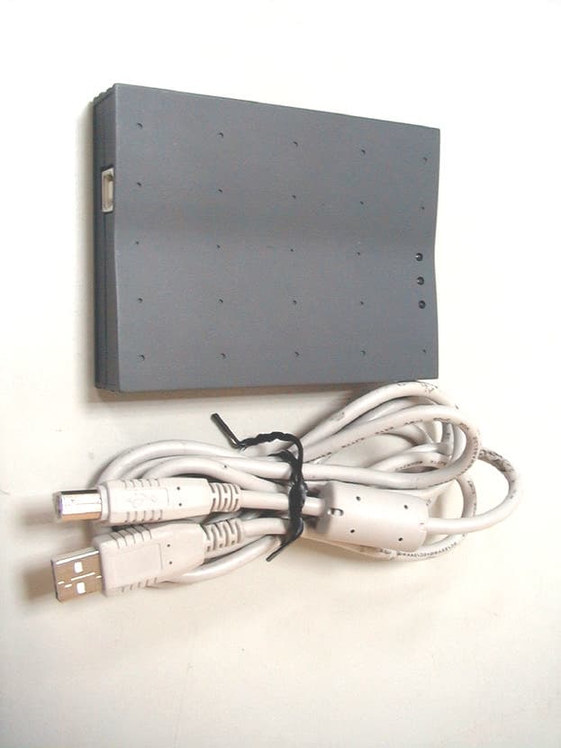
PGCWL-2111
Dec 13, 2001Wireless LAN USB Adaptor
Equipment Class
DTS - Digital Transmission System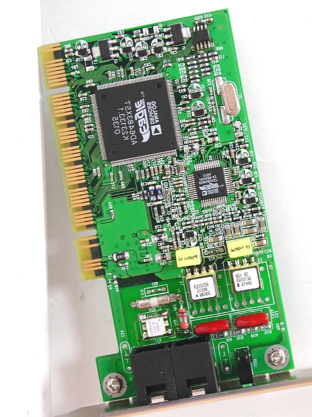
PGCAD-1310
Nov 29, 2001ADI ADSL Modem
Equipment Class
JBP - Part 15 Class B Computing Device Peripheral
PGCWL-3111
Sep 11, 2001Wireless Access Point
Equipment Class
DTS - Digital Transmission System
PGCAD-9711
Apr 16, 2001ADSL Add-on Card
Equipment Class
JBP - Part 15 Class B Computing Device Peripheral
PGCAD-1130
Apr 16, 2001ADSL Modem with USB Interface
Equipment Class
JBP - Part 15 Class B Computing Device Peripheral