PGCWL-3111Wireless Access Point
UAT Inc.
Click to zoom
Application Details
- Equipment Class
- DTS - Digital Transmission System
- Date of Grant
- Sep 11, 2001
- Application Purpose
- Original Equipment
- Date of Application
- Sep 11, 2001
- Equipment Note
- Wireless Access Point
- Frequency Range
- 2412.00000000 - 2462.00000000
- Company
- UAT Inc.
- Country
- Taiwan
Documents & Files
Document Text
Text extracted from the exhibit documents filed with the FCC. Open a document above to read the original.
Users Manual
Wireless Access Point WL-3111 User’s Manual This document contains confidential information and is proprietary to UAT Inc. No part of this document may be reproduced in any form or by any means without the prior permission of UAT Inc. All specifications are subject to change without notice. UAT Inc. 2F, No.5, Alley22, Lane 513, Jui Kuang Rd, Nei Hu, Taipei, Taiwan, R.O.C Tel: (886) 2 8797 8488 Fax: (886) 2 2657 0997 WL-3111 User’s Manual 1 Copyright Copyright © 2001, All rights reserved. This manual and software described in it are copyrighted with all rights reserved. This manual may not be copied, in whole or in part, without written consent. All product names are trademarks and or registered trademarks of their respective companies. WL-3111 User’s Manual 2 Table of Contents 1 Introduction 1.1 Package Contents................................................3 1.2 System Requirements...........................................4 1.3 Applications.........................................................4 1.4 Features & Benefits...............................................4 2 Setting the IP Address of AP 2.1 sing the Ethernet Port/Wireless Port...........................5 2.1.1 Using ARP/Ping commands..........................................5 2.1.2 DHCP client...............................................................6 3 Access Point Configuration 3.1 Using the Ethernet Port/Wireless Port. ......................7 3.1.1 How to Install the SNMP Manager..................................7 3.1.1.1 ChangeMode..................................................................7 3.1.2 Using the SNMP Manager. ..........................................8 3.1.2.1 Connecting to the Access Point .........................................8 3.1.2.2 Configuring the Access Point/User Mode .............................9 4 Access Point Firmware Upgrade 4.1 Using the Ethernet Port/Wireless Port........................21 4.1.1 How to Install TFTP Client.............................................21 4.1.2 Using the TFTP Client/User Mode..................................21 4.1.3 Using the TFTP Client/Production Mode...........................22 4.1.4 How to Uninstall TFTP Client.........................................22 FCC Regulation..............................................................23 WL-3111 User’s Manual 3 1. Introduction The WL-3111 AP is a 11Mbps high-speed Access Point for wireless connectivity interoperable with IEEE 802.11b, 2.4GHz Direct Sequence Spread Spectrum (DSSS) compliant equipment. The figure 1-1 shows WL-3111 AP outline Figure 1-1 1.1 Package Contents Please make sure that you received the following with your WL-3111 Access Point. • One Access Point • One Ethernet Cable • One Power Adapter • One User Guide • One Installation CD WL-3111 User’s Manual 4 1.2 System Requirements Installation of the Access Point requires: • An A/C power adapter which supplies the power for the Access Point. • A 10Base-T Ethernet cable (RJ-45 connector) • A window-based PC/AT compatible computer 1.3 Applications The WL-3111 AP is easy to install and highly efficient. The following list is to describe many applications can be done through Access Point and related device such as PCMCIA card for Notebook, USB adapter for desktop PC. – Small Office and Home Office (SOHO) networks – Exhibition Centers/Fairs – Temporary Workgroups – Hard-to-Wire Buildings – Wireless Extensions to Wired Networks – Construction Sites – Training/Educational Facilities 1.4 Features & Benefits – High-speed 11Mbps data transmission. – Fully interoperable with IEEE 802.11b compliant products – WEP data encryption/decryption – DHCP client simplifies network administration – Read-Write access for the Hardware Configuration through the SNMP Manager – Web/Telnet/SNMP Management helps administrators to remotely configure or manage the Access Point with a Web Browser, Telnet or SNMP Protocol – Seamless Roaming Capability allows users to move to anywhere without losing network connection WL-3111 User’s Manual 5 2. Setting the IP Address of the AP The first step in using the WL-3111 AP is to set its IP Address. This procedure can be done through the Ethernet/Wireless port by using a combination of ARP/Ping commands and the SNMP Manager, or by the network DHCP server. 2.1 Using the Ethernet Port/Wireless Port You can set the Access Point IP Address using the ARP/ping commands or by the network DHCP server. 2.1.1 Using ARP/Ping commands In order to set the Access Point IP address you need to know the Access Point MAC address. Follow the steps below giving the Access Point a temporary address at the beginning (Step A) and saving the IP address through the SNMP Manager application (Step B). Step A: 1. Connect an Ethernet station and the Access Point on the same subnet. The simplest way to accomplish that is to connect the Access Point and the Ethernet station to the same hub. You need to check if the station IP address and the Subnet mask are configured properly. Also the new IP address for the Access Point must correspond to the Subnet mask. 2. Open an MS-DOS Prompt window and enter a static route in the ARP table for the new IP address you want to assign. Use the ARP -s command to do that: ARP -s "new-IP-address" "AP-MAC-address" (The MAC-address of the Access Point is indicated in the back of the Access Point board. For example: ARP-s 10.170.254.27 00-04-25-02-00-10 3. Ping the Access Point, using its new IP address. For example: ping 10.170.254.27 If you get a ping reply, then the IP address has been temporarily set. In order to set it permanently you need to proceed to Step B without powering off the Access Point. Step B: 1. Open the SNMP Manager application. In order to install the SNMP Manager application, please refer to paragraph 3.1.1 “How to Install the SNMP Manager”. 2. Connect to the access point by selecting the “Connect AP” submenu under the “File” menu. Type the IP address of the access point (which has been temporarily set in S…
Text truncated - open the document above for the full version.
ID Label/Location Info
LABEL Format: This device complies with Part 15 of the FCC Rules Operation is subject to the following two conditions: (1) This device may not cause harmful interference, and (2) This device must accept any interference received, including interference that may cause undesired operation Model No.:WL-3111 FCC ID:PGCWL-3111 LABEL Size: 45 x 30 mm LABEL Position:
RF Exposure Info
Antenna Specification RF Exposure Calculations From FCC 1.1310 table 1A, the maximum permissible RF exposure for an uncontrolled environment is 1mW/cm 2 . The Electric field generated for a 1mW/cm 2 exposure (S) is calculated as follows: S = E 2 / Z Where: S = Power density E = Electric field Z = Impedance. 1mW/cm 2 = 10 W/m 2 The impedance of free space is 337 ohms, where E and H fields are perpendicular. Thus: = 61.4 V/m which is equivalent to 1mW/cm 2 Using the relationship between Electric field E, Power in watts P, and distance in meters d, the corresponding Antenna numeric gain G and the transmitter output power and solving for d, The Numeric gain G of antenna with a gain specified in dB is determined by: G = Log -1 (dB gain/10) G = Log -1 (2.48.0/10) = 1.770 E = S x Z E = 10 x 377 P eak x 30 x G d = E Notice in Installation Manual: While installing and operating this transmitter and antenna combination the radio frequency exposure limit of 1mW/cm 2 may be exceeded at distances close to the antennas installed. Therefore, the user must maintain a minimum distance of 20cm from the antenna at all time. The table in follow page identifies the distances where the 1mW/cm 2 exposure limits may be exceeded during continuous transmission using the antenna Antenna Type Gain (dBi) Gain Numeric Peak Output Power (mW) Calculated RF Exposure Separation Distance (cm) Minimum RF Exposure Separation Distance (cm) Dipole2.481.77010.5680.38620 RF SAFETY MPE calculation for this Wall mounted Mobile device (at 20 cm) According to OET BULLETIN 56 Fourth Edition/August 1999, Equation for Predicting RF Fields: = 5.214 x 10 -3 mW/cm 2 Where: S = power density (in appropriate units, e.g. mW/cm2) P = power input to the antenna (in appropriate units, e.g., mW) G = power gain of the antenna in the direction of interest relative to an isotropic radiator R = distance to the center of radiation of the antenna (appropriate units, e.g., cm) S = PG 4R 2 S = 10.568 x 1.770 4 2
Test Report
Test Repot ----------------------------------------------------------------------------------- 1/50 Report No.: U1215381 Training Research Co., Ltd., TEL: 886-2-26935155, Fax: 886-2-26934440 MEASUREMENT REPORT of WIRELESS ACCESS POINT Applicant: UAT Inc. Model No.:WL-3111 EUT:Wireless Access Point FCC ID:PGCWL-3111 Report No.:U1215381 Test by : Training Research Co., Ltd. TEL : 886-2-26935155 FAX : 886-2-26934440 2, Lane 194, Huan-Ho Street, Hsichih, Taipei Hsien 221, Taiwan, R.O.C. Test Repot ----------------------------------------------------------------------------------- 3/50 Report No.: U1215381 Training Research Co., Ltd., TEL: 886-2-26935155, Fax: 886-2-26934440 Tables of Contents I. GENERAL ............................................................................................................................. 5 1.1 Introduction ........................................................................................................................ 5 1.2 Description of EUT ............................................................................................................ 6 1.3 Description of Support Equipment ...................................................................................... 7 1.4 Configuration of System Under Test .................................................................................... 7 1.5 Verify the Frequency and Channel ...................................................................................... 8 1.6 Test Procedure ................................................................................................................... 9 1.7 Location of the Test Site ..................................................................................................... 9 1.8 General Test Condition ....................................................................................................... 9 II. Section 15.207: Power line conducted emissions for AC powered units ........................... 10 2.1 Test Condition & Setup .................................................................................................... 10 2.2 List of Test Instruments ..................................................................................................... 10 2.3 Test Configuration ............................................................................................................ 11 2.4 Test Result of Conducted Emissions .................................................................................. 12 III. Section 15.247(a)(2): Bandwidth for direct sequence system ............................................ 16 3.1 Test Condition & Setup .................................................................................................... 16 3.2 Test Instruments Configuration .......................................................................................... 16 3.3 List of Test Instruments ..................................................................................................... 16 3.4 Test Result of Bandwidth .................................................................................................. 17 IV. Section 15.247(a) (2) : Power Output .................................................................................. 21 4.1 Test Condition & Setup .................................................................................................... 21 4.2 List of Test Instruments ..................................................................................................... 22 4.3 Test Result ....................................................................................................................... 22 Test Repot ----------------------------------------------------------------------------------- 4/50 Report No.: U1215381 Training Research Co., Ltd., TEL: 886-2-26935155, Fax: 886-2-26934440 V. Section 15.247(c) (2) : Spurious Emissions (Radiated) .................................................... 25 5.1 Test Condition & Setup .................................................................................................. 25 5.2 List of Test Instruments ................................................................................................... 26 5.3 Test Instruments Configuration ........................................................................................ 27 5.4 Test Result of Spurious Radiated Emissions ..................................................................... 28 VI. Section 15.247(d) : Power Spectral Density ..................................................................... 40 6.1 Test Condition & Setup .................................................................................................. 40 6.2 Test Instruments Configuration ........................................................................................ 41 6.3 List of Test Instruments.................................................................................................... 41 6.4 Test Result of Power Spectral Density ............................................................................ 42 6.5 Required of Carrier Frequency ....................................................................................... 46 Appendix A: Set Up Procedure ................................................................................................ 49 Appendix C: Part15.203 ........................................................................................................... 50 Test Repot ----------------------------------------------------------------------------------- 5/50 Report No.: U1215381 Training Research Co., Ltd., TEL: 886-2-26935155, Fax: 886-2-26934440 GENERAL 1.1 Introduction The following measurement report is submitted on behalf of Applicant in support of a wireless access point certification in accordance with Part 2 Subpart J and Part 15 Subpart A and C of the Commission's Rules and Regulations. 1.2 Description of EUT EUT:Wireless A…
Text truncated - open the document above for the full version.
Test Setup Photos
Test Repot ---------------------------------------------------------------------------------- 11/50 Report No.: U1215381 Training Research Co., Ltd., TEL: 886-2-26935155, Fax: 886-2-26934440 2.3 Test configuration Conducted Emissions Test Placement
Test Setup Photos
Test Repot ---------------------------------------------------------------------------------- 27/50 Report No.: U1215381 Training Research Co., Ltd., TEL: 886-2-26935155, Fax: 886-2-26934440 5.3 Test Instruments Configuration Front View of the Test Configuration Rear View of the Test Configuration The test configuration for frequency between 1GHz to 18GHz is same as above.
Contact Information
Applicant
Tom Chen(Manager, R & D)
Technical Contact
Training Research Co. Ltd.Jack Tsai
[email protected]+886 2 26935155
2, Lane 194, Huan Ho Street, Hsichih · Taipeei Hsien · Taiwan
Test Firm
Training Research Co., Ltd.Jack Tsai
Technical Specifications
| # | Rule Parts | Frequency Range | Power Output |
|---|---|---|---|
| 1 | 15C | 2.41 GHz - 2.46 GHz | 11.00 mW |
Other Applications from UAT Inc.
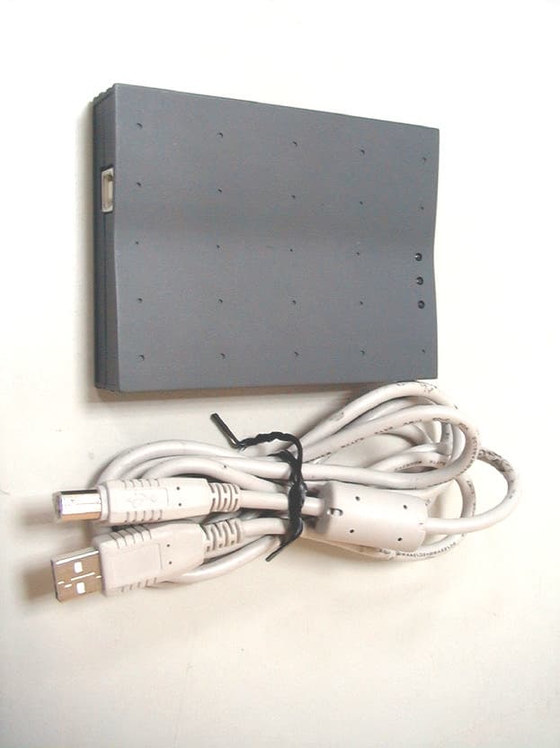
PGCWL-2111
Dec 13, 2001Wireless LAN USB Adaptor
Equipment Class
DTS - Digital Transmission System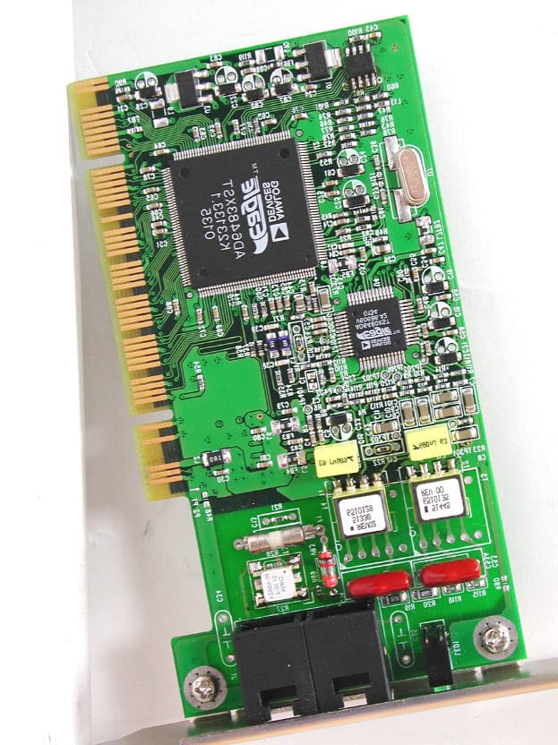
PGCAD-1310
Nov 29, 2001ADI ADSL Modem
Equipment Class
JBP - Part 15 Class B Computing Device Peripheral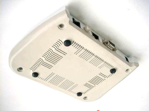
PGCAR-1150
Oct 10, 2001ADSL Router
Equipment Class
JBP - Part 15 Class B Computing Device Peripheral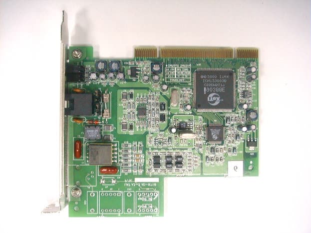
PGCAD-9711
Apr 16, 2001ADSL Add-on Card
Equipment Class
JBP - Part 15 Class B Computing Device Peripheral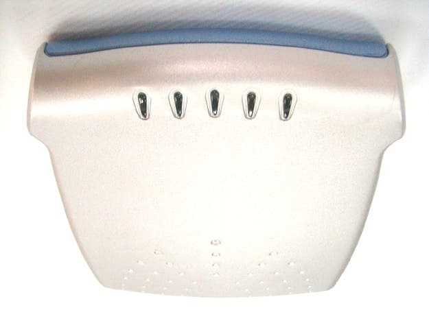
PGCAD-1130
Apr 16, 2001ADSL Modem with USB Interface
Equipment Class
JBP - Part 15 Class B Computing Device Peripheral