PGCAD-9711ADSL Add-on Card
UAT Inc.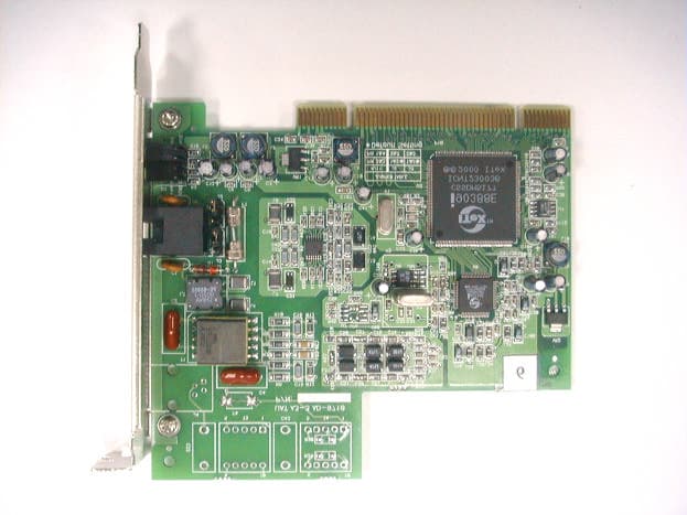
Click to zoom
Application Details
- Equipment Class
- JBP - Part 15 Class B Computing Device Peripheral
- Date of Grant
- Apr 16, 2001
- Application Purpose
- Original Equipment
- Date of Application
- Apr 16, 2001
- Equipment Note
- ADSL Add-on Card
- Company
- UAT Inc.
- Country
- Taiwan
Documents & Files
Document Text
Text extracted from the exhibit documents filed with the FCC. Open a document above to read the original.
Users Manual
Quick Start ADSL Modm Card Table of Contents Congratulations!................................................................................................................1 Step 1 – Know your PC’s Operating System...............................................................1 Step 2 – Determine your Connection Settings...........................................................2 Step 3 – Install the ADSL Modem Card.......................................................................3 Step 4 – Install the Drivers and Make a Connection.................................................5 Windows 95A....................................................................................................................6 Windows 95B.....................................................................................................................8 Windows 98, 98SE...........................................................................................................11 Setting the ADSL Configuration...........................................................................13 Making a RFC 1483 or RFC 1577 connection - 95A, 95B, 98, 98SE .................14 Making a RFC 2364 connection - 95A, 95B, 98, 98SE........................................18 Windows 2000.................................................................................................................19 Setting the ADSL Configuration...........................................................................21 Making a RFC 1483 or RFC 1577 connection - 2000 ..........................................22 Making a RFC 2364 connection - 2000.................................................................24 Windows NT4.0 - RFC 1483 or RFC 1577....................................................................25 Setting the ADSL Configuration for RFC 1483 or RFC 1577.............................27 Windows NT4.0 - RFC 2364...........................................................................................28 Setting the ADSL Configuration for RFC 2364...................................................31 Creating a Dial-up Network Connection......................................................................32 Appendix Editing your Service Connection..................................................................................33 Removing Drivers............................................................................................................34 Diagnostic Tools.............................................................................................................35 Trouble Shooting............................................................................................................37 Connector Pin-out...........................................................................................................38 LED Functions.................................................................................................................38 System Requirements & Compliance information......................................................39 Copyright & Regulatory Information...........................................................................39 1 Congratulations! You are about to accelerate into ADSL technology. Your new ADSL modem card is an internal Asymmetric Digital Subscriber Line (ADSL) PCI modem card, which conveniently plugs into your computer system. The modem connects directly to your telephone line via a standard connector. This guide is designed to walk you through installation of your ADSL Modem card in the easiest and quickest way possible. Please follow the instructions carefully. Step 1 – Know your PC’s Operating System You will need to know the exact version of Microsoft Windows installed in your computer. If you do not know or are unsure, please proceed as follows to determine your version of the Microsoft Operating System. On your desktop, right-click My Computer. Then select Properties. The version number of the Microsoft Windows Operating System installed in your computer will be displayed on the General tab. Refer to the following table for more detailed information. Windows OS System Properties Description Release (Microsoft Web) Win 95A4 00 950AWindows 95 OSR1 Win 95B 4.00.950BWindows 95 OSR2 Win 984.10.1998 Window 98 Win 98SE 4.10.2222A 2nd EditionWindows 98 2nd Edition Win 2000 5.00.2195 Windows 2000 Win NT 4.00.1381 Windows NT 4.0 If you have questions regarding your PC system and the Microsoft Windows Operating System, please contact your original PC manufacturer or Microsoft for assistance. Before Installing the ADSL PCI Modem Card, it is important to verify that the ADSL data port RJ-11 jack is configured so that the center two pins, pins 3 and 4, are used for ADSL data, otherwise the ADSL PCI modem card will not make a proper connection. If the ADSL 2 data port installation uses pins 2 and 5 for data, then a wiring converter will be required. Do not alter or remove a wiring converter if present. Consult with your ADSL service provider regarding a wiring converter or before attempting any wiring changes. 3 Step 2 – Determine your Connection settings You need to know your PC systems Windows OS and Internet Protocol supplied by your ADSL service provider. Refer to the following chart for your ADSL Driver. Protocol Selection RFC1483 !!Bridged Ethernet over ATM RFC2364 !!Point-to-Point Protocol over ATM RFC1577 !!Classical Internet Protocol over ATM RFC2516 !!Point-to-Point Protocol over Ethernet ADSL Driver Selection RFC1483 RFC2364 RFC1577 RFC2516 Win 95A & 95B 1483w95 2364w95 1577w95 See Note! Win 98 & 98SE 1483w98 2364w98 1577w98 See Note! Win NT 4.0 1483nt4 2364nt4 1577nt4 See Note! Win 2000 1483w2k 2364w2k 1577w2k See Note! Note! : RFC2516 (Point-to-Point Protocol over Ethernet) is supported by third party developers. See the PPPoE driver supplement for detailed information and installation instructions. Having determined the ADSL Driver you will be installing, you now n…
Text truncated - open the document above for the full version.
Block Diagram
EXHIBIT E Block Diagram
Cover Letter(s)
From: trc168 [[email protected]] Sent: Wednesday, March 28, 2001 11:45 PM To: Mike Kuo Subject: Re: UAT, Inc. FCC ID:PGCAD-9711, AN01T1233 Dear Mike Kuo: Anser #1: The user manual has been modified as the attachmant(U1215687C.PDF). Anser #2: The file size is less than 3 MB. Thank you very much! ----- Original Message ----- From: Mike Kuo <[email protected]> To: <[email protected]>; <[email protected]> Sent: Saturday, March 10, 2001 3:18 AM Subject: UAT, Inc. FCC ID:PGCAD-9711, AN01T1233 > Question #1: User manual does not contain the information required in 15.21 > of FCC rules. Please revise user manual. > > Question #2: The file size for User manual is over 3MB. Please reduce the > file size to less than 3 MB. > > The items indicated above must be submitted before processing can continue > on the above referenced application. Failure to provide the requested > information within 60 days of the original e-mail date may result in > application dismissal and forfeiture of the filing fee. Also, please note > that partial responses increase processing time and should not be submitted. > Any questions about the content of this correspondence should be directed to > the e-mail address listed below the name of the sender > > Best Regards > > ========================= > Mike Kuo > Compliance Certification Services > 561F Monterey Road > Morgan Hill CA 95037 > Telephone number:408-463-0885 EXT:105 > Fax number :408-463-0888 > E-Mail:[email protected] >
ID Label/Location Info
List of Exhibit EXHIBIT A Sample Label EXHIBIT B Test Report EXHIBIT C User Manual EXHIBIT D Circuit Diagram EXHIBIT E Block Diagram EXHIBIT F Photographs of EUT EXHIBIT A Sample Label LABEL Format: This device complies with Part 15 of the FCC Rules Operation is subject to the following two conditions: (1) This device may not cause harmful interference, and (2) This device must accept any interference received, including interference that may cause undesired operation. FCC ID : PGCAD-9711 Model No.: AD-9711 LABEL Size: 45 X30 mm LABEL Position: LABEL
Internal Photos
EXHIBIT F Photographs of EUT
Test Report
EXHIBIT B Test Report Test Report --------------------------------------------------------------------------- 2/13 Report No.: U1215687 Training Research Co., Ltd., TEL: 886-2-26461146, Fax: 886-2-26461778 Contents Chapter 1 Introduction Description of EUT.....................................................................................................................3 Configuration of Test Setup.........................................................................................................4 List of Support Equipment...........................................................................................................5 Chapter 2 Conducted Emission Test Test Condition and Setup............................................................................................................7 Conducted Test Placement..........................................................................................................8 Chapter 3 Radiated Emission Test Test Condition and Setup............................................................................................................9 Radiated Test Placement............................................................................................................10 Appendix A : Conducted test result..................................................................................................................11 Appendix B : Radiated test result.....................................................................................................................12 Test Report --------------------------------------------------------------------------- 3/13 Report No.: U1215687 Training Research Co., Ltd., TEL: 886-2-26461146, Fax: 886-2-26461778 Chapter 1 Introduction Description of EUT: The EUT features the following: • Plug and Play PCI 2.1 interface • Rate Adaptive ADSL technology that adapts to your phone line conditions • Receive line rate up to 10Mbps (downstream) and transmit line rate up to 1Mbps(upstream). Test method: The applicant provides the testing program. Pretest was found that the emission of operating mode is worse than standby mode. So, The final test is made at the operating mode. There is a DSL Lab test system for ADSL located at the far end side. While testing, the EUT was active all the way. During the pretest, two types: “AD-9710” and “AD-9711” were tested. The radiated pretest was found that the “AD-9711” type was the worse one. The test placement as the photographs showed is the worst case emission placed. (If the emission is close to the ambient, the resolution BW and view resolution will be reduced and the data will be recorded by detection of maximum hold peak mode.) The testing configuration of test setup is showing in the next page. Test Report --------------------------------------------------------------------------- 4/13 Report No.: U1215687 Training Research Co., Ltd., TEL: 886-2-26461146, Fax: 886-2-26461778 Configuration of test setup To Far-end DSL Lab test system Connections: PC: *Power port --- via a 185cm long, non-shield, no ferrite bead, power cable to the AC power source. *Serial port --- via a 76cm shielded RS-232 cable to an external modem. *Printer port --- a printer with 1.80m length data cable. *Monitor port --- a monitor with 1.80m long of data cable. *Keyboard port --- a keyboard with 1.50m length data cable. *Mouse port --- a mouse with 1.50m length data cable. *USB port A --- a joystick with 1.50m long, shielded and no ferrite bead data cable. *USB port B --- a joystick with 1.50m long, shielded and no ferrite bead data cable. (Each port on PC is connected with suitable device) EUT: *Phone port --- via a 2.1m long, non-shielded, no ferrite core, RJ-11 cable to the telephone. *Line port -- via a 30m long, non-shielded, no ferrite core, RJ-11 cable to the line jack of Far-end DSL Lab test system. Power souse USB Joystick Printer Mouse keyboard Monitor PC modem USB Joystick telephone EUT Test Report --------------------------------------------------------------------------- 5/13 Report No.: U1215687 Training Research Co., Ltd., TEL: 886-2-26461146, Fax: 886-2-26461778 List of support equipment Conducted test: PC : HP Brio 85xx 6/350 Model No. : D6928A Serial No. : SG91801432 FCC ID : N/A : 3872H013 Power type : 100 ~ 230VAC / 50 ~ 60Hz, 5A, Switching Power cord : Non-shielded, 2.33m long, Plastic, No ferrite core Monitor : HP Model No. : D2821 Serial No. : TW 73512262 FCC ID : A3KMO64 Power type : AC 110~120 / 220~240 VAC, Switching Power cord : Non-Shielded, 3m long, no ferrite core Data cable : Shielded, 1.8m long, with ferrite core Keyboard : HP Model No. : SK-2501K Serial No. : M990308909 FCC ID : GYUR38SK : 3862A621 Power type : By PC Data cable : Shielded, 1.73m long, with ferrite core Mouse : HP Model No. : M-S34 Serial No. : LZB90714106 FCC ID : DZL211029 : 4862A011 Power type : By PC Power cord : Non-shielded, 1.88m long, No ferrite core Test Report --------------------------------------------------------------------------- 6/13 Report No.: U1215687 Training Research Co., Ltd., TEL: 886-2-26461146, Fax: 886-2-26461778 Modem : ACEEX Model No. : DM-1414V FCC ID : IFAXDM1414 Power type : 120VAC, 60Hz/ 9VAC, 1A Power cord : Non-shielded, 1.9m long, no ferrite cord Data cable : RS232, Shielded, 1.2m long, no ferrite core RJ11C x 2, 7’ long non-shielded, no ferrite core Printer : HP Model No. : C2642A Serial No. : SG69A196GV FCC ID : B94C2642X Power type : 220VAC, 50Hz Power cord : Non-shielded, 2m long, no ferrite core Data cable : Shielded, 1.84m long, no ferrite core (1.7m) USB Joystick : Padix Model No. : QF-606U, QF-707U Serial No. : N/A, 8100848 FCC ID : N/A, Doc Approval Power type : Powered by PC Power Cable : Shielded, 1.5M long, No ferrite bead data cable DSL Lab test system: AWARE Model No. : ADS-005002 Serial No. : 006060 Power type : Switching Adaptor Power cord : Shielded, 2.1m long, no ferrite bead Test Report ------------------------------------------------------…
Text truncated - open the document above for the full version.
Test Setup Photos
Test Report --------------------------------------------------------------------------- 8/13 Report No.: U1215687 Training Research Co., Ltd., TEL: 886-2-26461146, Fax: 886-2-26461778 Conducted Test Placement: (Photographs) Test Report --------------------------------------------------------------------------- 10/13 Report No.: U1215687 Training Research Co., Ltd., TEL: 886-2-26461146, Fax: 886-2-26461778 Radiated Test Placement: (Photographs)
Contact Information
Applicant
Tom Chen(Manager, R & D)
Technical Contact
Training Research Co., Ltd.Jacob Lin
[email protected]8862-2646-1146
2, Lane 194, Huan-Ho Street · Taipei Hsien · Taiwan
Test Firm
Training Research Co., Ltd.Jack Tsai
Technical Specifications
| # | Rule Parts | Frequency Range | Power Output |
|---|---|---|---|
| 1 | 15B | - | - |
Other Applications from UAT Inc.
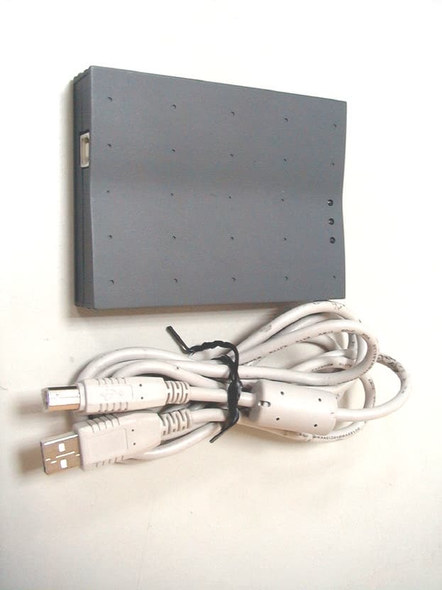
PGCWL-2111
Dec 13, 2001Wireless LAN USB Adaptor
Equipment Class
DTS - Digital Transmission System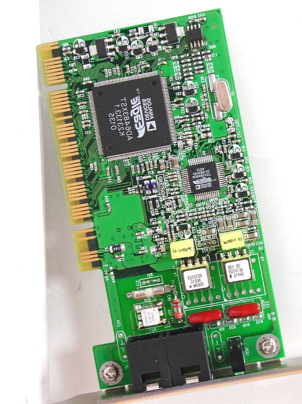
PGCAD-1310
Nov 29, 2001ADI ADSL Modem
Equipment Class
JBP - Part 15 Class B Computing Device Peripheral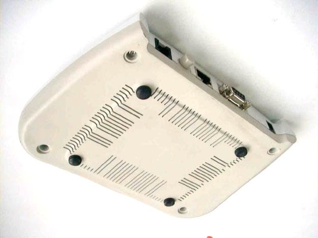
PGCAR-1150
Oct 10, 2001ADSL Router
Equipment Class
JBP - Part 15 Class B Computing Device Peripheral
PGCWL-3111
Sep 11, 2001Wireless Access Point
Equipment Class
DTS - Digital Transmission System
PGCAD-1130
Apr 16, 2001ADSL Modem with USB Interface
Equipment Class
JBP - Part 15 Class B Computing Device Peripheral