PJO2600GSM Cellphone
Arima Communication Corporation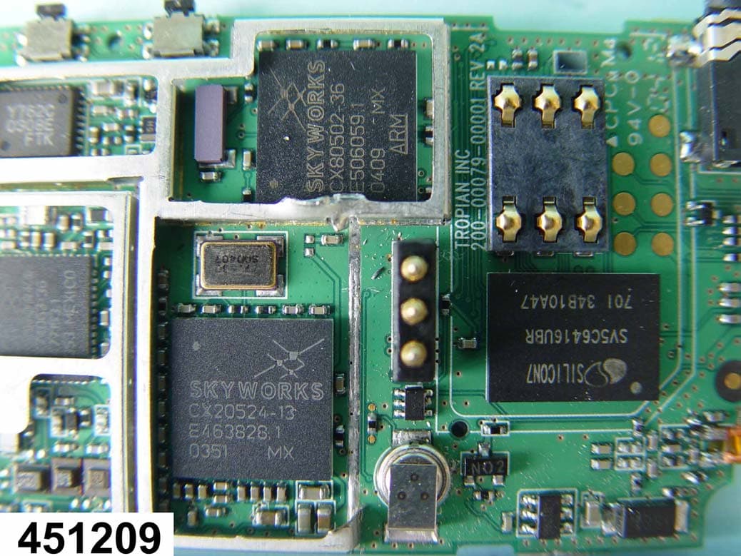
Click to zoom
Application Details
- Equipment Class
- PCE - PCS Licensed Transmitter held to ear
- Date of Grant
- Jul 15, 2004
- Application Purpose
- Original Equipment
- Date of Application
- Jul 15, 2004
- Equipment Note
- GSM Cellphone
- Frequency Range
- 1850.20000000 - 1909.80000000
- Country
- Taiwan
Documents & Files
Document Text
Text extracted from the exhibit documents filed with the FCC. Open a document above to read the original.
Users Manual
2600 Operation Manual Contents Your phone • Keys and connectors Getting started • Installing the SIM card and the battery • Charging the battery • Switching the phone on and off Call functions • Making a call • Answering or rejecting an incoming call • Call waiting • Handling more than one call Menu functions 1. Messages 2. Sound Settings 3. LCD Settings 4. Fun and Tools 5. Call Log 6. Phonebook 7. WAP 8. Phone Settings 9. Call Services 10. Security General information Care and Maintenance Your phone Keys and connectors Earpiece Side key Main display Power on/End call key Left soft key Right soft key Power on key Navigation key Numeric key # key ¼ key Microphone Side key • During a call, adjusts the earpiece volume. • In standby mode, the keys adjust the ring volume. • To reject an incoming call, press the side key twice. Soft key • The current functions are displayed in the bottom line of LCD. The soft key display as shortcut to access the sub menu. • In standby mode, quick access to Profile WA P Phone book Message • In sub menu, use to scroll up and down to select an item to view • Long press to activate Silent mode Getting Started Installing the SIM Card and the Battery You need to insert the SIM card and charge the battery before using the phone. • Keep all miniature SIM cards out of the reach of small children. • Be careful to handle, insert or remove the SIM card since the SIM card and its contacts can easily be damaged by scratched or bending. • Before installing/removing the SIM card, always make sure that the phone is switched off. 1. Remove the battery – Slide the catch above the battery toward the top of the phone and lock it in position, then Lift the battery away. 2. Insert and slide the SIM card. Note: To remove the card, slide it to the left as shown in the diagram below. 3. Engage the battery with the bottom edge of the phone and then lower the other end until it clicks into place. Charging the Battery You must fully charge the battery before using your phone for the first time. 1. Connect the lead from the travel adapter to the socket on the bottom of your phone . 2. Connect the charger to an AC wall outlet. Note: You can use the phone while the charger is connected but charging is suspended during that time. Note: When the battery is low, the phone will emit a warning tone and display a warning message. When the battery becomes too low for the phone to operate, it switches off automatically. Basic Operations Switching the Phone on and off • Hold down the key for more than one second to switch the phone on. A start-up welcome message will appear briefly on the display. • Hold down the key for more than one second to switch the phone off. A power-off melody will sound to confirm the action. A “Good Bye” message will be briefly displayed on the screen. The phone will then switch off. Note: Make sure the phone is switched off before removing the battery; otherwise data that needs to be saved in the SIM may be lost. Make a Call • In standby mode, key in the number, including the area code, press . Note: Use Right/Left key to move the cursor and the to delete the character. Answer or Reject a Call • Press the ANSWER to accept the call. • To reject a call, briefly press the key. Hang Up To end a call, briefly press the key or close the flip-lid. The call timer will stop. A Call Ended message will briefly be shown on the display. Adjust the Volume Use the Up/Down keys on the side of the phone to adjust volume. Ringer volume, voice volume, and key-tone volume can be adjusted independently: • While the phone is ringing, the Up/Down keys adjust the ringer volume. • While in an active call, the keys adjust the voice volume. • While the phone is idle, the keys adjust the key-tone volume, which is the sound made when you press the phone keys if key tones are enabled. Redial a Previous Number 1. The phone stores the last 30 dialed numbers in its memory. 2. In idle mode pressing the key will display the previously called numbers. 3. If the same number is called several times, it will appear only once and the date, time, and duration information is associated with the last call to that number. 4. To redial a previously dialed number: • Select a desired number using the Up/Down key. • Press the key to initiate a call to that number. Put a Caller on Hold To place a call on hold: 1. Simply press the key or press the OPTIONS of call menu (activated by the right soft-key), and choose HOLD. You are then free to make another call. To reactivate a call that is on hold: 2. Simply press the key again or press the OPTIONS of call menu, and choose UNHOLD. Answer Another Call While in a Call This service is only available if you have subscribed to the Call Waiting supplementary service. If you receive a call while you are already in a call, the phone will play a tone and display a screen to identify the new caller. Also, the incoming call icon will blink until the waiting call has been connected. To accept the call and put the first caller on hold, press the key. To reject the call and return to the single active call, press the key. Input Method To change the input language selection: When key in text, long press the key. To Changing case: Press to change capital or lower-case letters. To Change input method: Press to change the input method (T9ab, T9Ab, T9AB, Abc, ABC, 0..9) Traditional English input • Press to and select the desired character. Note: Your phone provides Multi-tap function. For example, press twice to display the letter B, and press three times to display the letter C. Characters Table Key Characters 1 . , : ‘ ? ! - & 〜 _ / 1 2 A/a B/b C/c 2 ä á à â ã æ ç 3 D/d E/e F/f 3 è é ë ê 4 G/g H/h I/I 4 î ï í ì ı ğ 5 J/j K/k L/l 5 £ 6 M/m N/n O/o 6 ö ô ò ó Θ ñ 7 P/p Q/q R/r S/s 7 $ ß 8 T/t U/u V/v 8 ü û ú 9 W/w X/x Y/y Z/z 9 0 0 # To switch between ABC/abc/Abc * (space) Symbol Mode This mode is for typing symbols that are not available in the multi-tap mode. To enter Symbol Mode, long press…
Text truncated - open the document above for the full version.
Cover Letter(s)
Arima Communication Corp. No.16 Lane 658,Ying Tao Road, Yingko, Taipei Hsien, Taiwan Te l : +886-2-82277755 Fax: +886-2-82275533 June 24 2004 Power of Attorney To whom it may concern, Please be notified that we, Arima Communication Corp. , have assigned Sporton International Inc., located at No. 52, Hwa Ya 1 st Rd ., Hwa Ya Technology Park, Kwei-Shan Hsiang, Tao Yuan Hsien, Taiwan, R.O.C., as our agent. Any and all acts carried out by Sporton International Inc., on the matters of relating to FCC part 24, 15B and OET 65 Supplement C, Sporton International Inc. shall have the full responsitivity to guarantee all the accurate testing method and testing data. However, Arima Communication Corp. will be fully responsible for mass products to be in compliance with regulations. This authorization is limited to the product of as following: ( 1 ) GSM/GPRS Mobile Handset Model: Arima 2600 ( Brand: Not available yet ) Any acknowledgement and response, please send it to Sporton International Inc. directly. Should you have any questions or comments regarding this matter, please have my best attention. Sincerely yours, ______________________________ Chris Huang Arima Communication Corp. Tel: +886-2-82277755 Fax: +886-2-82275533 E-Mail: [email protected]
Cover Letter(s)
Arima Communication Corp. June 30, 2004 Federal Communications Commission Authorization and Evaluation Division FCC ID: PJO2600 Confidentiality Letter Request Pursuant to Section 0.457 and 0.459 of the Commission’s Rules, the Applicant hereby requests confidential treatment of information accompanying this Application as outlined below: 1. Schematic Circuitry Diagram 2. Functional Block Diagram 3. Tune-up procedure 4. Parts List (BOM) The above materials contain trade secrets and proprietary information not customarily released to the public. The public disclosure of these matters might be harmful to the Applicant and provide unjustify benefits to its competitors. The Applicants understands the pursant to Rule 0.457, disclosure of this Application and all accompanying documentation will not made before the date of the Grant for this application. Sincerely, _________________ June 30 2004 Chris Huang Arima Communication Corp.
Cover Letter(s)
American Telecommunications Certification Body Inc. 6731 Whittier Ave, McLean, VA 22101 July 15, 2004 RE: Arima Communication Corp. FCC ID: PJO2600 After a review of the submitted information, I have a few comments on the above referenced Application. Administrative Issues: 1) The users manual appears to be missing information regarding body worn and spacing requirements. Please updated. 2) The users manual mentions GSM/GPRS. However all data appears at a crest factor of 8.3. Please explain what maximum class level this device will function at for purposes GSM/GPRS. Technical Issues: 3) Please provide at least one SAR plot for each of the tilted positions in the test report. 4) From the test configuration photographs it can not be determined if the device had the microphone/earpiece installed during body worn SAR tests. Please explain. Timothy R. Johnson Examining Engineer mailto: [email protected] The items indicated above must be submitted before processing can continue on the above referenced application. Failure to provide the requested information may result in application termination. Correspondence should be considered part of the permanent submission and may be viewed from the Internet after a Grant of Equipment Authorization is issued. Please do not respond to this correspondence using the email reply button. In order for your response to be processed expeditiously, you must submit your documents through the AmericanTCB.com website. Also, please note that partial responses increase processing time and should not be submitted. Any questions about the content of this correspondence should be directed to the sender.
Cover Letter(s)
Response for PJO2600 1. Will be updated 2. It is GPRS class 8 cellular phone, so the crest factor is the same with GSM 3. Will be updated 4. The earpiece was blocked by the phone as pictured.
Internal Photos
FCC TEST REPORT REPORT NO. : F451209 SPORTON International Inc. PAGE NUMBER : B1 OF B11 TEL : 886-2-2696-2468 ISSUED DATE : July 8, 2004 FAX : 886-2-2696-2255 APPENDIX B. Internal Photographs of EUT FCC TEST REPORT REPORT NO. : F451209 SPORTON International Inc. PAGE NUMBER : B2 OF B11 TEL : 886-2-2696-2468 ISSUED DATE : July 8, 2004 FAX : 886-2-2696-2255 FCC TEST REPORT REPORT NO. : F451209 SPORTON International Inc. PAGE NUMBER : B3 OF B11 TEL : 886-2-2696-2468 ISSUED DATE : July 8, 2004 FAX : 886-2-2696-2255 FCC TEST REPORT REPORT NO. : F451209 SPORTON International Inc. PAGE NUMBER : B4 OF B11 TEL : 886-2-2696-2468 ISSUED DATE : July 8, 2004 FAX : 886-2-2696-2255 FCC TEST REPORT REPORT NO. : F451209 SPORTON International Inc. PAGE NUMBER : B5 OF B11 TEL : 886-2-2696-2468 ISSUED DATE : July 8, 2004 FAX : 886-2-2696-2255 FCC TEST REPORT REPORT NO. : F451209 SPORTON International Inc. PAGE NUMBER : B6 OF B11 TEL : 886-2-2696-2468 ISSUED DATE : July 8, 2004 FAX : 886-2-2696-2255 FCC TEST REPORT REPORT NO. : F451209 SPORTON International Inc. PAGE NUMBER : B7 OF B11 TEL : 886-2-2696-2468 ISSUED DATE : July 8, 2004 FAX : 886-2-2696-2255 FCC TEST REPORT REPORT NO. : F451209 SPORTON International Inc. PAGE NUMBER : B8 OF B11 TEL : 886-2-2696-2468 ISSUED DATE : July 8, 2004 FAX : 886-2-2696-2255 FCC TEST REPORT REPORT NO. : F451209 SPORTON International Inc. PAGE NUMBER : B9 OF B11 TEL : 886-2-2696-2468 ISSUED DATE : July 8, 2004 FAX : 886-2-2696-2255 FCC TEST REPORT REPORT NO. : F451209 SPORTON International Inc. PAGE NUMBER : B10 OF B11 TEL : 886-2-2696-2468 ISSUED DATE : July 8, 2004 FAX : 886-2-2696-2255 FCC TEST REPORT REPORT NO. : F451209 SPORTON International Inc. PAGE NUMBER : B11 OF B11 TEL : 886-2-2696-2468 ISSUED DATE : July 8, 2004 FAX : 886-2-2696-2255
Operational Description
OPERATIONAL DESCRIPTION OF THE ARIMA 2600 GSM PHONE The equipment under test (EUT) is the transmitter of the Arima Model 2600, a tri-band (900/1800/1900) GSM/GPRS mobile phone. The transmitter operates in a half-duplex system according to the GSM standards. The majority of the phone circuitry consists of a four device chipset; the CX74063 Transceiver IC, the CX77321 HBT IC Power Amplifier, the CX20524 Mixed Signal Device (analog/digital IC) and the CX80501/2 Baseband Processor. The remainder of the major radio components are the receiver SAW filters, transmit/receive switch and directional coupler. There is also a combination Flash Memory/SRAM IC. The system is powered by a rechargeable lithium-ion battery with a nominal voltage of 3.8 volts. The transmitter oscillators which comprise the translational loop architecture are internal to the transceiver IC and are phase locked to a 13 MHz reference signal derived from the 19.5 MHz crystal oscillator. The UHF local oscillator fractional-N phase lock loop operates on a fundamental frequency from 1353 MHz to 1506 MHz. This signal is divided by three for use in the 900 MHz GSM band, and is divided by three then multiplied by two for use as the DCS/PCS local oscillator. The main oscillators operate fundamentally on their respective GSM, DCS, or PCS band. The phase detector operates at 41 – 50 MHz when tuned to the GSM band, and between 80 – 102 MHz for the DCS/PCS bands. The main oscillator signals are amplified by the power amplifier, routed to the directional coupler, transmit/receive (T/R) switch and finally delivered to the antenna. The directional coupler samples the output RF signal which is subsequently detected by a temperature compensated Schottky diode RF detector. The detected signal is used in the integrating power control loop which resides internal to the transceiver IC for setting and controlling the output power. The power settings are calibrated at the factory and stored in the flash memory IC. These settings are used as the reference level for the power control loop. Power ramping functions are also controlled by the mixed signal device. The GMSK modulation is provided in-loop by quadrature I/Q signals which are sent to the transceiver IC from the mixed-signal device which converted the digital stream from the baseband processor into an analog signal used by the modulator. The mixed signal device is controlled by the baseband processor. The RF performance conforms to the ETSI specifications for spectrum due to modulation, transient switching modulation spectrum, power ramp, and power output, as well as all the other ETSI requirements. The receiver is a direct-conversion design, therefore an intermediate frequency (IF) SAW filter is not used in this design. The RF preamplifiers are internal to the transceiver and provide the signal to the sub-harmonically (1/2 frequency) pumped mixers. Sallen-Key lowpass filters, variable gain amplifiers, and DC offset correction circuits comprise the remainder of the receiver. The received signals now at baseband frequencies are routed from the transceiver to the mixed-signal device for further processing and ultimately to the baseband processor. The mixed signal device digitizes the baseband I/Q signals using Sigma-Delta DACs and sends them to the baseband processor through a serial digital interface. This IC also has analog-to-digital converters (ADCs) and digital-to-analog converters (DACs) to directly interface to the handset speaker and microphone. The voiceband Codec section provides a 32 ohm interface to the speaker and microphone and also provides Line In/Out signals for the headset. Additional the mixed signal device contains all required system power supply regulators. The baseband processor handles all physical layer radio control signals and network interfaces. The 32 KHz clock oscillator operates the baseband IC from a backup battery when the main battery is removed. The baseband processor is a dual-core device that splits the processing between a DSP core and an ARM-7 THUMB ™ processor. The DSP handles the physical and layer 1 processing, while the ARM7 executes the layer 2 and layer 3 protocol and the man-machine interface (MMI). The dual cores communicate through a dedicated block of dual port memory. It also communicates with the Subscriber Identity Module (SIM) through an interface to the mixed signal device. The baseband processor also communicates to the calibration system or external devices through a digital serial link that is available on the system connector. The other main signals on the system connector include the digital audio interface (DAI) and allows for an external battery charging voltage. The MMI completes the phone design and includes the displays, keypads, vibration motor, LEDs, speaker, microphone, and headset.
RF Exposure Info
©2004 SPORTON International Inc..SAR Testing Lab This report shall not be reproduced except in full, without the written approval of Sporton. Rev.01 FCC SAR Test Report Test Report No ﹕ O442004-1-2-01 Specific Absorption Rate (SAR) Test Report for Arima Communication Corp. on the GSM900/DCS1800/PCS1900 Triple Band Mobile Phone Report No. : O442004-1-2-01 Trade Name : Arima Model Name : 2600 FCC ID : PJO2600 Date of Testing : June 21, 2004 Date of Report. : June 23, 2004 Date of Review : June 24, 2004 The test results refer exclusively to the presented test model/sample only. Without written approval of SPORTON International Inc., the test report shall not be reproduced except in full. SPORTON International Inc. 6F, No.106, Sec. 1, Hsin Tai Wu Rd., Hsi Chih, Taipei Hsien, Taiwan, R.O.C. ©2004 SPORTON International Inc..SAR Testing Lab This report shall not be reproduced except in full, without the written approval of Sporton. Rev.01 Tel:886-22696-2468 Fax:886-2-2696-2255 FCC SAR Test Report Test Report No ﹕ O442004-1-2-01 Table of Contents 1. Statement of Compliance---------------------------------------------------------------------------------------- 1 2. Administration Data ------------------------------------------------------------------------------------------------ 2 2.1 Testing Laboratory---------------------------------------------------------------------------------------------- 2 2.2 Detail of Applicant---------------------------------------------------------------------------------------------- 2 2.3 Detail of Manfacturer------------------------------------------------------------------------------------------- 2 2.4 Application Detail----------------------------------------------------------------------------------------------- 2 3.General Information ------------------------------------------------------------------------------------------------ 3 3.1 Descripton of Device Under Test (DUT)--------------------------------------------------------------------- 3 3.2 Product Photo---------------------------------------------------------------------------------------------------- 4 3.3 Applied Standards:---------------------------------------------------------------------------------------------- 5 3.4 Device Category and SAR Limits----------------------------------------------------------------------------- 6 3.4 Test Conditions:-------------------------------------------------------------------------------------------------- 6 3.4.1 Ambient Condition-------------------------------------------------------------------------------------- 6 3.4.2 Test Configuration-------------------------------------------------------------------------------------- 6 4.Specific Absorption Rate (SAR) -------------------------------------------------------------------------------- 7 4.1 Introduction------------------------------------------------------------------------------------------------------ 7 4.2. SAR Definition-------------------------------------------------------------------------------------------------- 7 5. SAR Measurement Setup---------------------------------------------------------------------------------------- 8 5.1.DASY4 E-Field Probe System--------------------------------------------------------------------------------- 9 5.1.1.ET3DV6 E-Field Probe Specification--------------------------------------------------------------- 10 5.1.2 ET3DV6 E-Field Probe Calibration---------------------------------------------------------------- 10 5.2 DATA Acquisition Electronics (DAE)----------------------------------------------------------------------- 11 5.3 Robot------------------------------------------------------------------------------------------------------------- 12 5.4 Measurement Server------------------------------------------------------------------------------------------- 12 5.5 SAM Twin Phantom-------------------------------------------------------------------------------------------- 12 5.6. Device Holder for SAM Twin Phantom--------------------------------------------------------------------- 14 5.7 Data Storage and Evaluation--------------------------------------------------------------------------------- 15 5.7.1 Data Storage-------------------------------------------------------------------------------------------- 15 5.7.2 Data Evaluation---------------------------------------------------------------------------------------- 15 5.8. Test Equipment List-------------------------------------------------------------------------------------------- 18 6. Tissue Simulating Liquids -------------------------------------------------------------------------------------- 19 7. Uncertainty Assessment----------------------------------------------------------------------------------------- 21 8. SAR Measurement Evaluation -------------------------------------------------------------------------------- 23 8.1 Purpose of System Performance check---------------------------------------------------------------------- 23 8.2 System Setup---------------------------------------------------------------------------------------------------- 23 8.3Validation Results----------------------------------------------------------------------------------------------- 25 9. Description for DUT Testing Position ---------------------------------------------------------------------- 26 10. Measurement Procedures-------------------------------------------------------------------------------------- 31 10.1 Spatial Peak SAR Evaluation------------------------------------------------------------------------------- 31 10.2 Scan Procedures---------------------------------------------------------------------------------------------- 32 ©2004 SPORTON International Inc..SAR Testing Lab This report shall not be reproduced except in full, without the written approval of Sporton. Rev.01 Tel:886-22696-2468 Fax:886-2-2696-2255 FCC SAR Test Report Test Report No ﹕ O442004-1-2-01 10.3 SAR Averaged Methods-----------------…
Text truncated - open the document above for the full version.
RF Exposure Info
©2004 SPORTON International Inc..SAR Testing Lab This report shall not be reproduced except in full, without the written approval of Sporton. Rev.01 FCC SAR Test Report Test Report No ﹕ O442004-1-2-01 ©2004 SPORTON International Inc..SAR Testing Lab This report shall not be reproduced except in full, without the written approval of Sporton. Rev.01 FCC SAR Test Report Test Report No ﹕ O442004-1-2-01 ©2004 SPORTON International Inc..SAR Testing Lab This report shall not be reproduced except in full, without the written approval of Sporton. Rev.01 FCC SAR Test Report Test Report No ﹕ O442004-1-2-01 ©2004 SPORTON International Inc..SAR Testing Lab This report shall not be reproduced except in full, without the written approval of Sporton. Rev.01 FCC SAR Test Report Test Report No ﹕ O442004-1-2-01 ©2004 SPORTON International Inc..SAR Testing Lab This report shall not be reproduced except in full, without the written approval of Sporton. Rev.01 FCC SAR Test Report Test Report No ﹕ O442004-1-2-01 ©2004 SPORTON International Inc..SAR Testing Lab This report shall not be reproduced except in full, without the written approval of Sporton. Rev.01 FCC SAR Test Report Test Report No ﹕ O442004-1-2-01 ©2004 SPORTON International Inc..SAR Testing Lab This report shall not be reproduced except in full, without the written approval of Sporton. Rev.01 FCC SAR Test Report Test Report No ﹕ O442004-1-2-01 ©2004 SPORTON International Inc..SAR Testing Lab This report shall not be reproduced except in full, without the written approval of Sporton. Rev.01 FCC SAR Test Report Test Report No ﹕ O442004-1-2-01 ©2004 SPORTON International Inc..SAR Testing Lab This report shall not be reproduced except in full, without the written approval of Sporton. Rev.01 FCC SAR Test Report Test Report No ﹕ O442004-1-2-01 ©2004 SPORTON International Inc..SAR Testing Lab This report shall not be reproduced except in full, without the written approval of Sporton. Rev.01 FCC SAR Test Report Test Report No ﹕ O442004-1-2-01 ©2004 SPORTON International Inc..SAR Testing Lab This report shall not be reproduced except in full, without the written approval of Sporton. Rev.01 FCC SAR Test Report Test Report No ﹕ O442004-1-2-01 ©2004 SPORTON International Inc..SAR Testing Lab This report shall not be reproduced except in full, without the written approval of Sporton. Rev.01 FCC SAR Test Report Test Report No ﹕ O442004-1-2-01 ©2004 SPORTON International Inc..SAR Testing Lab This report shall not be reproduced except in full, without the written approval of Sporton. Rev.01 FCC SAR Test Report Test Report No ﹕ O442004-1-2-01 ©2004 SPORTON International Inc..SAR Testing Lab This report shall not be reproduced except in full, without the written approval of Sporton. Rev.01 FCC SAR Test Report Test Report No ﹕ O442004-1-2-01 ©2004 SPORTON International Inc..SAR Testing Lab This report shall not be reproduced except in full, without the written approval of Sporton. Rev.01 FCC SAR Test Report Test Report No ﹕ O442004-1-2-01 ©2004 SPORTON International Inc..SAR Testing Lab This report shall not be reproduced except in full, without the written approval of Sporton. Rev.01 FCC SAR Test Report Test Report No ﹕ O442004-1-2-01 ©2004 SPORTON International Inc..SAR Testing Lab This report shall not be reproduced except in full, without the written approval of Sporton. Rev.01 FCC SAR Test Report Test Report No ﹕ O442004-1-2-01 ©2004 SPORTON International Inc..SAR Testing Lab This report shall not be reproduced except in full, without the written approval of Sporton. Rev.01 FCC SAR Test Report Test Report No ﹕ O442004-1-2-01 ©2004 SPORTON International Inc..SAR Testing Lab This report shall not be reproduced except in full, without the written approval of Sporton. Rev.01 FCC SAR Test Report Test Report No ﹕ O442004-1-2-01 ©2004 SPORTON International Inc..SAR Testing Lab This report shall not be reproduced except in full, without the written approval of Sporton. Rev.01 FCC SAR Test Report Test Report No ﹕ O442004-1-2-01 ©2004 SPORTON International Inc..SAR Testing Lab This report shall not be reproduced except in full, without the written approval of Sporton. Rev.01 FCC SAR Test Report Test Report No ﹕ O442004-1-2-01
Test Report
FCC TEST REPORT Report No. : F451209 SPORTON International Inc. FCC ID PJO2600 TEL : 886-2-2696-2468 Pa ge No. 1 of 69 FAX : 886-2-2696-2255 Issued Date July 8,2004 FCC TEST REPORT for 47 CFR Part 24E Equipment : GSM900/DCS1800/PCS1900 Triple Band Mobile Phone Model No. : 2600 FCC ID : PJO2600 Filing Type : Certification Applicant : Arima Communication Corp. No. 16, Lane 658, Ying Tao Road, Yingko, Taipie Hsien, Taiwan The test result refers exclusively to the test presented test model / sample. Without written approval of SPORTON International Inc., the test report shall not be reproduced except in full. Certificate or Test Report must not be used by the applicant to claim the product in this test report endorsement by NVLAP or any agency of U.S. government. SPORTON International Inc. 6F, No.106, Sec. 1, Hsin Tai Wu Rd., Hsi Chih, Taipei Hsien, Taiwan, R.O.C. FCC TEST REPORT Report No. : F451209 SPORTON International Inc. FCC ID PJO2600 TEL : 886-2-2696-2468 Pa ge No. 2 of 69 FAX : 886-2-2696-2255 Issued Date July 8,2004 The applicant has been cautioned as to the following: 15.21 Information to User. The users manual or instruction manual for an intentional radiator shall caution the user that changes or modifications not expressly approved by the party responsible for compliance could void the user's authority to operate the equipment. 15.27(a) Special Accessories. Equipment marketed to a consumer must be capable of complying with the necessary regulations in the configuration in which the equipment is marketed. Where special accessories, such as shielded cables and/or special connectors are required to enable an unintentional or intentional radiator to comply with the emission limits in this part, the equipment must be marketed with, i.e. shipped and sold with, those special accessories. However, in lieu of shipping or packaging the special accessories with the unintentional or intentional radiator, the responsible party may employ other methods of ensuring that the special accessories are provided to the consumer, without additional charge. Information detailing any alternative method used to supply the special accessories for a grant of equipment authorization or retained in the verification records, as appropriate. The party responsible for the equipment, as detailed in § 2.909 of this chapter, shall ensure that these special accessories are provided with the equipment. The instruction manual for such devices shall include appropriate instructions on the first page of text concerned with the installation of the device that these special accessories must be used with the device. It is the responsibility of the user to use the needed special accessories supplied with the equipment. FCC TEST REPORT Report No. : F451209 SPORTON International Inc. FCC ID PJO2600 TEL : 886-2-2696-2468 Pa ge No. 3 of 69 FAX : 886-2-2696-2255 Issued Date July 8,2004 Table of Contents Rule Description Page Test Report 4 2.1033(c) General Information Required 5 2.1033(c)(14) Rule Summary 9 General Information 10 Standard Test Conditions and Engineering Practices 11…
Text truncated - open the document above for the full version.
Contact Information
Applicant
Jay Chiang(Senior Engineer)
Technical Contact
Sporton International Inc.Daniel Lee
[email protected]886-3-327-3456
No.52, Hwa-Ya 1st Rd. · Tao Yuan Hsien · Taiwan
Non-Technical Contact
Sporton International Inc.Daniel Lee
[email protected]886-3-327-3456
Test Firm
Sporton International Inc.W Huang
Technical Specifications
| # | Rule Parts | Frequency Range | Power Output | Emission | Tolerance |
|---|---|---|---|---|---|
| 1 | 24E | 1.85 GHz - 1.91 GHz | 427.00 mW | 300KGXW | 0.0600000000 ppm |
Other Applications from Arima Communication Corporation
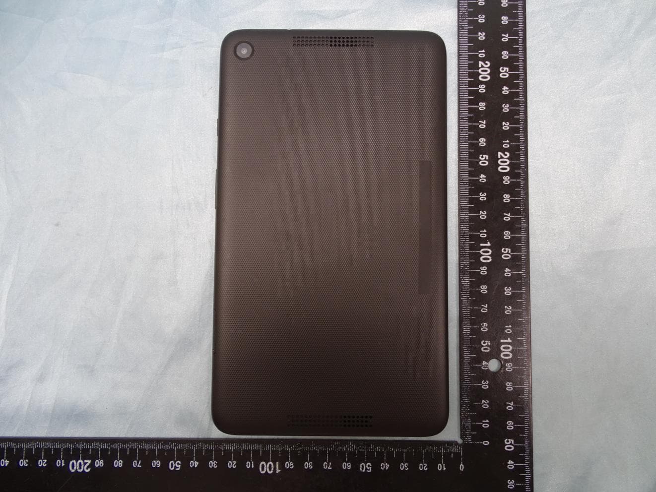
PJO6901
Jun 23, 2020MT-T800
Equipment Class
DTS - Digital Transmission System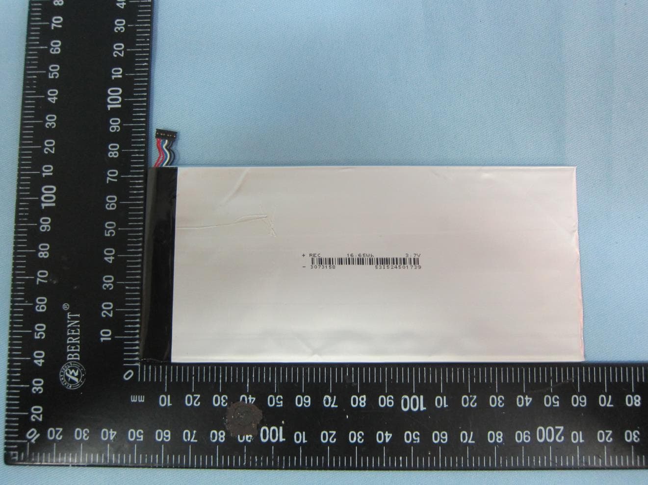
PJONBX208HQCG
Aug 17, 2015tablet
Equipment Class
DXX - Part 15 Low Power Communication Device Transmitter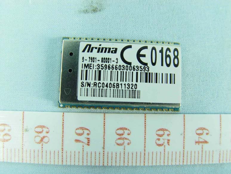
PJO7902
May 04, 2010GPRS 850/1900 module
Equipment Class
PCB - PCS Licensed Transmitter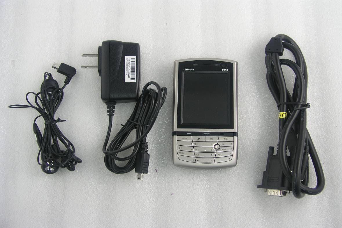
PJO9002
Oct 18, 20073.5G PDA WLAN
Equipment Class
DTS - Digital Transmission System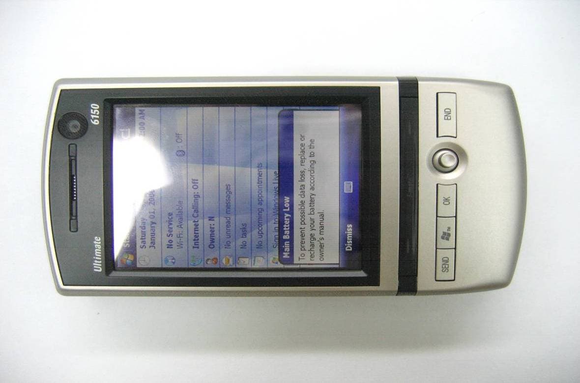
PJO9001
Aug 29, 20073.5G PDA Bluetooth
Equipment Class
DSS - Part 15 Spread Spectrum Transmitter