PJOGSA190PCS Band Cell Phone
Arima Communication Corporation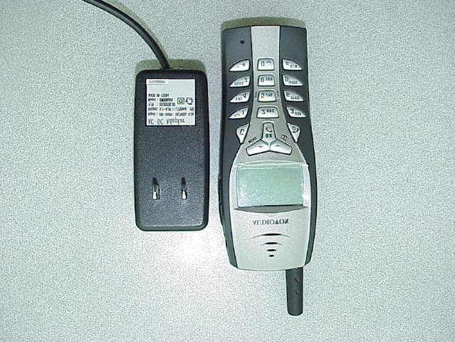
Click to zoom
Application Details
- Equipment Class
- PCE - PCS Licensed Transmitter held to ear
- Date of Grant
- May 10, 2001
- Application Purpose
- Original Equipment
- Date of Application
- Mar 13, 2001
- Equipment Note
- PCS Band Cell Phone
- Frequency Range
- 1850.00000000 - 1910.00000000
- Country
- Taiwan
Documents & Files
Document Text
Text extracted from the exhibit documents filed with the FCC. Open a document above to read the original.
Attestation Statements
Arima Communication Co. Ltd. Addr:16, Lane 658, Ying Tao Road, YingKo, ZIP 239, Taipei County, Taiw an Republic Of China Tel: + 886 2 2670 5577 (Operator) Fax: + 886 2 2670 5511 Contact Person: T a-M ing, Benjamin, Lee T itl e:Deputy Director of Sal es& Product M arketing ___________________________________________________________________________________________ Date: 2001/3/15 Page: 1 of 1D:\Ready_To_Convert\Doc\140432.DOC Communication Change of model name Arima Communication Corp. requests that the equipment tested under the model name • M2001C will be marketed under the model name • M2051C This change is only for internal administration reasons. We assure that the products are electrically and mechanically 100% identical.
Cover Letter(s)
Arima Communication Co. Ltd. Addr:16, Lane 658, Ying Tao Road, YingKo, ZIP 239, Taipei County, Taiw an Republic Of China Tel: + 886 2 2670 5577 (Operator) Fax: + 886 2 2670 5511 Contact Person: T a-M ing, Benjamin, Lee T itl e:Deputy Director of Sal es& Product M arketing ___________________________________________________________________________________________ Date: 2001/3/15 Page: 1 of 1D:\Ready_To_Convert\Doc\140437.DOC Communication CONFIDENTIALITY REQUEST Arima Communication Corp. Requests that the following material be withheld from public inspection following the grant of the Equipment Authorization: M2051c 1900-Block_Diagram M2051c BOM M2051C schematics ECN1900_M2000V9.1_Component_Bottom ECN1900_M2000V9.1_Component_Top ECN1900_M2000V9.1_Schematic These exhibits contain information relating to the circuit function and complexity that could be of benefit to competitors. The material contains trade secrets and confidential information that Arima Communication Corp. does not customarily release to the public and which is otherwise not available to the public.
Cover Letter(s)
Mar 21, 2001 CONFIDENTIALITY REQUEST Federal Communications Commission Authorization and Evaluation Division 7435 Oakland Mills Road Columbia, MD 21046 Re:Arima Communication Corp , application for certification of a Cellular phone for use in the PCS Band. FCC ID:PJOGSA190 [ORIGINALLY FILED AS PJO-M2051C, REQUEST FOR CHANGE TO NEW ID HAS BEEN FILED] Gentlemen: Arima Communication Corp, herein submits an Application for Equipment Authorization to be followed by submission of a fee for $640.00 along with Form 159 for certification of a Cellular Handset under FCC Rules Part 24 as required by the FCC Rules. Arima requests, pursuant to 47CFR 0.459, post grant confidentiality for portions of the material contained in this application such that the identified material will be withheld from public inspection following the grant of this authorization. This material, as indicated by request for confidentiality of the item during the electronic submission process and further identified below, includes: 1. Sche matic diagra ms 2. Block diagrams 3. Parts list Specifically, these exhibits contain information relating to circuit function and complexity that could be of benefit to competitors. The material contains trade secrets and confidential information that Arima does not customarily release to the public and which is otherwise not generally available to the public. Please contact the undersigned by phone at 410-531-3439, by fax at 410-531-0807, by email at [email protected], or by correspondence at the address below if there are any further questions or additional information needed concerning this filing. Rega rds, (signed) Phillip Inglis, TRP/Cetecom b.v.b.a. 14085 Howard Rd. Dayton, MD. 21036
Cover Letter(s)
Mar 21, 2001 Federal Communications Commission Authorization and Evaluation Division 7435 Oakland Mills Road Columbia, MD 21046 Re:Arima Communication Corp , application for certification of a Cellular phone for use in the PCS Band. FCC ID:PJOGSA190 [ORIGINALLY FILED AS PJO-M2051C, REQUEST FOR CHANGE TO NEW ID HAS BEEN FILED] Gentlemen: Arima Communication Corp, herein request that the application filed under FCC ID:PJO- M2051C be changed to FCC ID:PJO-GSA190. This change is requested as a result of a change in marketing plans. A revised label has been uploaded to the pending application. Label location remains unchanged. Please contact the undersigned by phone at 410-531-3439, by fax at 410-531-0807, by email at [email protected], or by correspondence at the address below if there are any further questions or additional information needed concerning this filing. Rega rds, (signed) Phillip Inglis, TRP/Cetecom b.v.b.a. 14085 Howard Rd. Dayton, MD. 21036
Cover Letter(s)
Mar 27, 2001 Federal Communications Commission Authorization and Evaluation Division 7435 Oakland Mills Road Columbia, MD 21046 Re:Arima Communication Corp, application for certification of a Cellular phone for use in the PCS Band. FCC ID:PJOGSA190 [ORIGINALLY FILED AS PJO-M2051C, REQUEST FOR CHANGE TO NEW ID HAS BEEN FILED] Gentlemen: Arima Communication Corp, herein request that the application filed under FCC ID:PJO- M2051C be changed to FCC ID:PJOGSA190. This change is requested as a result of a change in marketing plans. A revised label has been uploaded to the pending application. Label location remains unchanged. Please contact the undersigned by phone at 410-531-3439, by fax at 410-531-0807, by email at [email protected], or by correspondence at the address below if there are any further questions or additional information needed concerning this filing. Regards, (signed) Phillip Inglis, TRP/Cetecom b.v.b.a. 14085 Howard Rd. Dayton, MD. 21036
External Photos
Photographs of the equipment Photograph no.: 1 Photographs of the equipment Photograph no.: 2
ID Label/Location Info
Below is the drawing of the proposed FCC ID label. This Label will be located on the bottom of the phone below the batter y. PJO is the Grantee Code that was assigned FCC ID:PJO-M2051C
ID Label/Location Info
Below is the drawing of the proposed FCC ID label. This Label will be located on the bottom of the phone below the batter y. PJO is the Grantee Code that was assigned FCC ID:PJO-M2051C
ID Label/Location Info
Below is the drawing of the proposed FCC ID label. This Label will be located on the bottom of the phone below the batter y. PJO is the Grantee Code that was assigned FCC ID:PJOGSA190
ID Label/Location Info
Photographs of the equipment FCC ID Label Location FCCID:PJOGSA190
Internal Photos
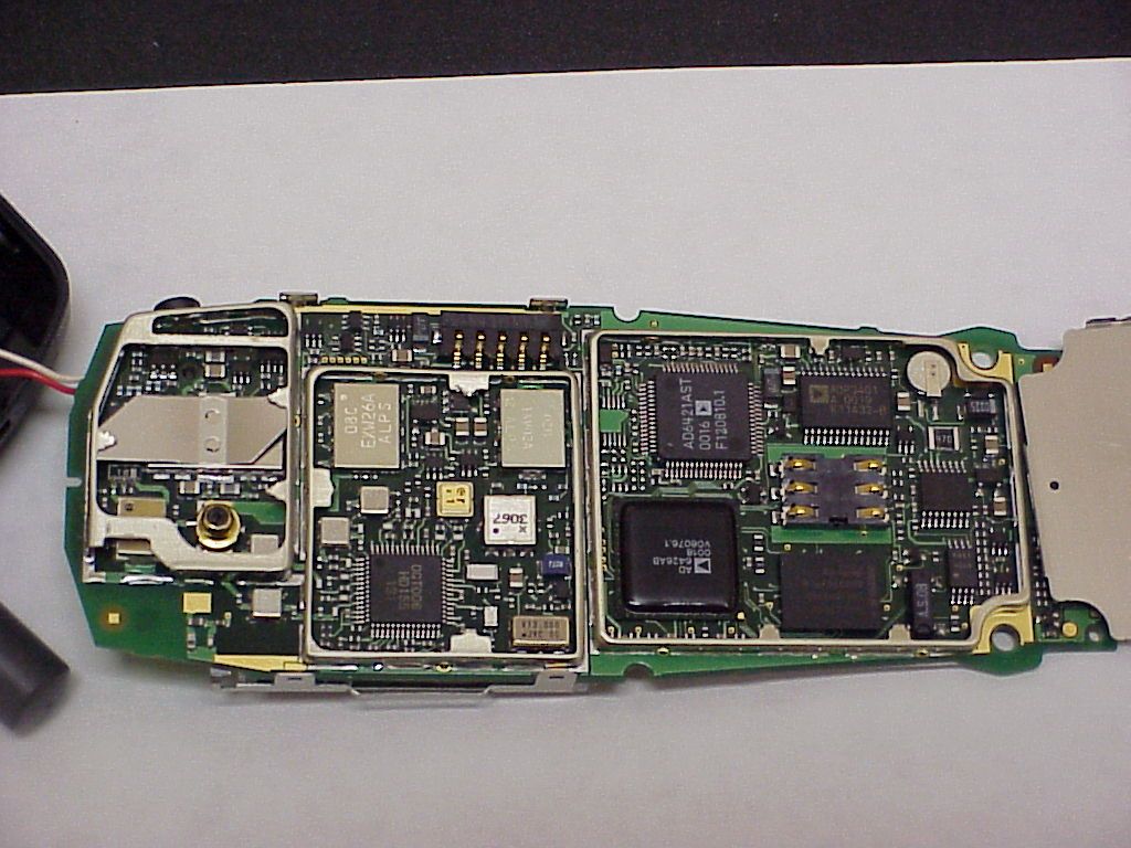
Photographs of the equipment Photograph no.: 3 Photographs of the equipment Photograph no.: 4 Photographs of the equipment Photograph no.: 5 Photographs of the equipment Photogtaph no. 6
Test Report
CETECOM CETECOM Inc . 411 Dixon Landing Road, Milpitas, CA-95035, USA Phone: +1 408 586 6200 Fax: +1 408 586 6299 CETECOM ICT Services GmbH Radio Satellite Communication Untertürkheimer Straße 6-10 . D-66117 Saarbrücken Telefon: +49 (0)681 598-9100 Telefax: -9075 I ssued test report consist of 57 PagesPage 1 (57 ) Test report no.: 110/2001C FCC Part 24 FCC ID : TBD Accredited Testing Laboratory DAR-Registration number: TTI-P-G 166/98-00 CETECOM Inc. Test report no. : 110/2001CIssue date: 2001.02.08Page 2 (57) Table of Contents 1 General information 1.1 Notes 1.2 Testing laboratory 1.3 Details of applicant 1.4 Application details 1.5 Test item 1.6 Test standards 2 Technical test 2.1 Summary of test results 2.2 Test report 1 General information 1.1 Notes The test results of this test report relate exclusively to the test item specified in 1.5. The CETECOM Inc. does not assume responsibility for any conclusions and generalisations drawn from the test results with regard to other specimens or samples of the type of the equipment represented by the test item. The test report may only be reproduced or published in full. Reproduction or publication of extracts from the report requires the prior written approval of the CETECOM Inc. 1.2Testing laboratory CETECOM Inc . 411 Dixon Landing Road, Milpitas, CA-95035, USA Phone: +1 408 586 6200 Fax: +1 408 586 6299 E-mail: [email protected] Internet: www.cetecomusa.com CETECOM ICT Services GmbH Radio Satellite Communication Untertürkheimer Straße 6-10 . D-66117 Saarbrücken Telefon: +49 (0)681 598-9100 Telefax: -9075Internet CETECOM Inc. Test report no. : 110/2001CIssue date: 2001.02.08Page 3 (57) 1.3Details of applicant Name : Arima Communication Corporation Street Add.: 6 th Floor, No. 349, Jen Ho Rd., Sec.2, Ta Shi City : Tao Yuan-335 Country : Taiwan Telephone : +886 3390 9877 Telefax : +886 3380 4609 Contact : Ben Lee e-mail : [email protected] Telephone : +886 3390 9877 1.4Application details Date of receipt of application : 2001-01-20 Date of receipt of test item : 2001-01-25 Date of test : 2001-02-05 & 2001-02-08 1.5Test item Manufacturer:applicant Type of equipment :Cellular Phone Model No. :M20001C Serial number:A10804000002 Additional informations: : Frequency:PCS-1900 Type of modulation:GSM/PCS Number of channels : Antenna:Dipole Power supply:3.6 V Lithium Ion Battery Output power:29.35dBm Peak / ERP : 29.9dBm (Burst); EIRP: 32.0dBm (Burst) EUT Temp. Tolerance:Temperature range : -30°C - +50°C 1.6Test standards: FCC Part 24 CETECOM Inc. Test report no. : 110/2001CIssue date: 2001.02.08Page 4 (57) 2 Technical test 2.1Summary of test results No deviations from the technical specification(s) were ascertained in the course of the tests performed. Technical responsibility for area of testing : 2001-02-08EMCLothar Schmidt DateSectionNameSignature CETECOM Inc. Test report no. : 110/2001CIssue date: 2001.02.08Page 5 (57) 2.2Test report TEST REPORT Test report no.: 110/2001 C CETECOM Inc. Test report no. : 110/2001CIssue date: 2001.02.08Page 6 (57) TEST REPORT REFERENCE LIST OF MEASUREMENTS PARAMETER TO BE MEASURED ParagraphPAGE POWER OUTPUT SUBCLAUSE § 24.232 7 FREQUENCY STABILITY SUBCLAUSE § 24.235 12 EMISSIONS LIMITS §24.238 14 CONDUCTED SPURIOUS EMISSIONS31 OCCUPIED BANDWIDTH §2.989 38 CONDUCTED EMISSIONS § 15.107/207 45 TEST EQUIPMENT AND ANCILLARIES USED FOR TESTS 47 TEST SITE 48 PHOTOGRAPHS OF THE EQUIPMENT 52 CETECOM Inc. Test report no. : 110/2001CIssue date: 2001.02.08Page 7 (57) POWER OUTPUT SUBCLAUSE § 24.232 Summary: This paragraph contains both average , peak output powers and EIRP measurements for the EUT. In all cases, the peak output power is within the required mask (this mask is specified in the JTC standards, TIA PN3389 Vol. 1 Chap 7, and is no FCC requirement). Method of Measurements: The EUT was set up for the max. output power with pseudo random data modulation. The power was measured with R&S Spectrum Analyzer FSEM 30 ( peak and average) This measurements were done at 3 frequencies, 1850.2 MHz, 1880.0 MHz and 1909.8 MHz (bottom, middle and top of operational frequency range) Limits: Power StepNominal Peak Output Power (dBm) Tolerance (dB) 0+30 ± ±± ± 2 Power Measurements: Conducted: F requency (MHz) Power Step Peak Output P ower (dBm) Average Output P ower (dBm) 1850.2029.3520.28 1880.0029.2920.22 1909.8029.1720.10 Measurement uncertainty ± ±± ± 0.5 dB CETECOM Inc. Test report no. : 110/2001CIssue date: 2001.02.08Page 8 (57) EIRP Measurements Description: This is the test for the maximum radiated power from the EUT. Rule Part 24.232(b) specifies that "Mobile/portable stations are limited to 2 watts e.i.r.p. peak power..." and 24.232(c) specifies that "Peak transmit power must be measured over any interval of continuous transmission using instrumentation calibrated in terms of an rms-equivalent voltage." Method of Measurement: 1. In an anechoic antenna test chamber, a half-wave dipole antenna for the frequency band of interest is placed at the reference center of the chamber. An RF Signal source for the frequency band of interest is connected to the dipole with a cable that has been constructed to not interfere with the radiation pattern of the antenna. A known (measured) power (Pin) is applied to the input of the dipole, and the power received (Pr) at the chamber's probe antenna is recorded. 2. A "reference path loss" is established as Pin + 2.1 - Pr. 3. The EUT is substituted for the dipole at the reference center of the chamber. The EUT is put into CW test mode and a scan is performed to obtain the radiation pattern. 4. From the radiation pattern, the co-ordinates where the maximum antenna gain occurs is identified. 5. The EUT is then put into pulse mode at its maximum power level (Power Step 0). 6. "Gated mode" power measurements are performed with the receiving antenna placed at the coordinates determined in Step 3 to determine the output power as defined in FCC Rule 24.232 (b) and (c). The "reference path…
Text truncated - open the document above for the full version.
Test Report
CETECOM CETECOM Inc . 411 Dixon Landing Road, Milpitas, CA-95035, USA Phone: +1 408 586 6200 Fax: +1 408 586 6299 CETECOM ICT Services GmbH Radio Satellite Communication Untertürkheimer Straße 6-10 . D-66117 Saarbrücken Telefon: +49 (0)681 598-9100 Telefax: -9075 I ssued test report consist of 57 PagesPage 1 (57 ) Test report no.: 110/2001C FCC Part 24 FCC ID : TBD Accredited Testing Laboratory DAR-Registration number: TTI-P-G 166/98-00 CETECOM Inc. Test report no. : 110/2001CIssue date: 2001.02.08Page 2 (57) Table of Contents 1 General information 1.1 Notes 1.2 Testing laboratory 1.3 Details of applicant 1.4 Application details 1.5 Test item 1.6 Test standards 2 Technical test 2.1 Summary of test results 2.2 Test report 1 General information 1.1 Notes The test results of this test report relate exclusively to the test item specified in 1.5. The CETECOM Inc. does not assume responsibility for any conclusions and generalisations drawn from the test results with regard to other specimens or samples of the type of the equipment represented by the test item. The test report may only be reproduced or published in full. Reproduction or publication of extracts from the report requires the prior written approval of the CETECOM Inc. 1.2Testing laboratory CETECOM Inc . 411 Dixon Landing Road, Milpitas, CA-95035, USA Phone: +1 408 586 6200 Fax: +1 408 586 6299 E-mail: [email protected] Internet: www.cetecomusa.com CETECOM ICT Services GmbH Radio Satellite Communication Untertürkheimer Straße 6-10 . D-66117 Saarbrücken Telefon: +49 (0)681 598-9100 Telefax: -9075Internet CETECOM Inc. Test report no. : 110/2001CIssue date: 2001.02.08Page 3 (57) 1.3Details of applicant Name : Arima Communication Corporation Street Add.: 6 th Floor, No. 349, Jen Ho Rd., Sec.2, Ta Shi City : Tao Yuan-335 Country : Taiwan Telephone : +886 3390 9877 Telefax : +886 3380 4609 Contact : Ben Lee e-mail : [email protected] Telephone : +886 3390 9877 1.4Application details Date of receipt of application : 2001-01-20 Date of receipt of test item : 2001-01-25 Date of test : 2001-02-05 & 2001-02-08 1.5Test item Manufacturer:applicant Type of equipment :Cellular Phone Model No. :M20001C Serial number:A10804000002 Additional informations: : Frequency:PCS-1900 Type of modulation:GSM/PCS Number of channels : Antenna:Dipole Power supply:3.6 V Lithium Ion Battery Output power:29.35dBm Peak / ERP : 29.9dBm (Burst); EIRP: 32.0dBm (Burst) EUT Temp. Tolerance:Temperature range : -30°C - +50°C 1.6Test standards: FCC Part 24 CETECOM Inc. Test report no. : 110/2001CIssue date: 2001.02.08Page 4 (57) 2 Technical test 2.1Summary of test results No deviations from the technical specification(s) were ascertained in the course of the tests performed. Technical responsibility for area of testing : 2001-02-08EMCLothar Schmidt DateSectionNameSignature CETECOM Inc. Test report no. : 110/2001CIssue date: 2001.02.08Page 5 (57) 2.2Test report TEST REPORT Test report no.: 110/2001 C CETECOM Inc. Test report no. : 110/2001CIssue date: 2001.02.08Page 6 (57) TEST REPORT REFERENCE LIST OF MEASUREMENTS PARAMETER TO BE MEASURED ParagraphPAGE POWER OUTPUT SUBCLAUSE § 24.232 7 FREQUENCY STABILITY SUBCLAUSE § 24.235 12 EMISSIONS LIMITS §24.238 14 CONDUCTED SPURIOUS EMISSIONS31 OCCUPIED BANDWIDTH §2.989 38 CONDUCTED EMISSIONS § 15.107/207 45 TEST EQUIPMENT AND ANCILLARIES USED FOR TESTS 47 TEST SITE 48 PHOTOGRAPHS OF THE EQUIPMENT 52 CETECOM Inc. Test report no. : 110/2001CIssue date: 2001.02.08Page 7 (57) POWER OUTPUT SUBCLAUSE § 24.232 Summary: This paragraph contains both average , peak output powers and EIRP measurements for the EUT. In all cases, the peak output power is within the required mask (this mask is specified in the JTC standards, TIA PN3389 Vol. 1 Chap 7, and is no FCC requirement). Method of Measurements: The EUT was set up for the max. output power with pseudo random data modulation. The power was measured with R&S Spectrum Analyzer FSEM 30 ( peak and average) This measurements were done at 3 frequencies, 1850.2 MHz, 1880.0 MHz and 1909.8 MHz (bottom, middle and top of operational frequency range) Limits: Power StepNominal Peak Output Power (dBm) Tolerance (dB) 0+30 ± ±± ± 2 Power Measurements: Conducted: F requency (MHz) Power Step Peak Output P ower (dBm) Average Output P ower (dBm) 1850.2029.3520.28 1880.0029.2920.22 1909.8029.1720.10 Measurement uncertainty ± ±± ± 0.5 dB CETECOM Inc. Test report no. : 110/2001CIssue date: 2001.02.08Page 8 (57) EIRP Measurements Description: This is the test for the maximum radiated power from the EUT. Rule Part 24.232(b) specifies that "Mobile/portable stations are limited to 2 watts e.i.r.p. peak power..." and 24.232(c) specifies that "Peak transmit power must be measured over any interval of continuous transmission using instrumentation calibrated in terms of an rms-equivalent voltage." Method of Measurement: 1. In an anechoic antenna test chamber, a half-wave dipole antenna for the frequency band of interest is placed at the reference center of the chamber. An RF Signal source for the frequency band of interest is connected to the dipole with a cable that has been constructed to not interfere with the radiation pattern of the antenna. A known (measured) power (Pin) is applied to the input of the dipole, and the power received (Pr) at the chamber's probe antenna is recorded. 2. A "reference path loss" is established as Pin + 2.1 - Pr. 3. The EUT is substituted for the dipole at the reference center of the chamber. The EUT is put into CW test mode and a scan is performed to obtain the radiation pattern. 4. From the radiation pattern, the co-ordinates where the maximum antenna gain occurs is identified. 5. The EUT is then put into pulse mode at its maximum power level (Power Step 0). 6. "Gated mode" power measurements are performed with the receiving antenna placed at the coordinates determined in Step 3 to determine the output power as defined in FCC Rule 24.232 (b) and (c). The "reference path…
Text truncated - open the document above for the full version.
Test Setup Photos
CETECOM CETECOM Inc . 411 Dixon Landing Road, Milpitas, CA-95035, USA Phone: +1 408 586 6200 Fax: +1 408 586 6299 CETECOM ICT Services GmbH Radio Satellite Communication Untertürkheimer Straße 6-10 . D-66117 Saarbrücken Telefon: +49 (0)681 598-9100 Telefax: -9075 I ssued test report consist of 57 PagesPage 1 (57 ) Test report no.: 110/2001C FCC Part 24 FCC ID : TBD Accredited Testing Laboratory DAR-Registration number: TTI-P-G 166/98-00 CETECOM Inc. Test report no. : 110/2001CIssue date: 2001.02.08Page 2 (57) Table of Contents 1 General information 1.1 Notes 1.2 Testing laboratory 1.3 Details of applicant 1.4 Application details 1.5 Test item 1.6 Test standards 2 Technical test 2.1 Summary of test results 2.2 Test report 1 General information 1.1 Notes The test results of this test report relate exclusively to the test item specified in 1.5. The CETECOM Inc. does not assume responsibility for any conclusions and generalisations drawn from the test results with regard to other specimens or samples of the type of the equipment represented by the test item. The test report may only be reproduced or published in full. Reproduction or publication of extracts from the report requires the prior written approval of the CETECOM Inc. 1.2Testing laboratory CETECOM Inc . 411 Dixon Landing Road, Milpitas, CA-95035, USA Phone: +1 408 586 6200 Fax: +1 408 586 6299 E-mail: [email protected] Internet: www.cetecomusa.com CETECOM ICT Services GmbH Radio Satellite Communication Untertürkheimer Straße 6-10 . D-66117 Saarbrücken Telefon: +49 (0)681 598-9100 Telefax: -9075Internet CETECOM Inc. Test report no. : 110/2001CIssue date: 2001.02.08Page 3 (57) 1.3Details of applicant Name : Arima Communication Corporation Street Add.: 6 th Floor, No. 349, Jen Ho Rd., Sec.2, Ta Shi City : Tao Yuan-335 Country : Taiwan Telephone : +886 3390 9877 Telefax : +886 3380 4609 Contact : Ben Lee e-mail : [email protected] Telephone : +886 3390 9877 1.4Application details Date of receipt of application : 2001-01-20 Date of receipt of test item : 2001-01-25 Date of test : 2001-02-05 & 2001-02-08 1.5Test item Manufacturer:applicant Type of equipment :Cellular Phone Model No. :M20001C Serial number:A10804000002 Additional informations: : Frequency:PCS-1900 Type of modulation:GSM/PCS Number of channels : Antenna:Dipole Power supply:3.6 V Lithium Ion Battery Output power:29.35dBm Peak / ERP : 29.9dBm (Burst); EIRP: 32.0dBm (Burst) EUT Temp. Tolerance:Temperature range : -30°C - +50°C 1.6Test standards: FCC Part 24 CETECOM Inc. Test report no. : 110/2001CIssue date: 2001.02.08Page 4 (57) 2 Technical test 2.1Summary of test results No deviations from the technical specification(s) were ascertained in the course of the tests performed. Technical responsibility for area of testing : 2001-02-08EMCLothar Schmidt DateSectionNameSignature CETECOM Inc. Test report no. : 110/2001CIssue date: 2001.02.08Page 5 (57) 2.2Test report TEST REPORT Test report no.: 110/2001 C CETECOM Inc. Test report no. : 110/2001CIssue date: 2001.02.08Page 6 (57) TEST REPORT REFERENCE LIST OF MEASUREMENTS PARAMETER TO BE MEASURED ParagraphPAGE POWER OUTPUT SUBCLAUSE § 24.232 7 FREQUENCY STABILITY SUBCLAUSE § 24.235 12 EMISSIONS LIMITS §24.238 14 CONDUCTED SPURIOUS EMISSIONS31 OCCUPIED BANDWIDTH §2.989 38 CONDUCTED EMISSIONS § 15.107/207 45 TEST EQUIPMENT AND ANCILLARIES USED FOR TESTS 47 TEST SITE 48 PHOTOGRAPHS OF THE EQUIPMENT 52 CETECOM Inc. Test report no. : 110/2001CIssue date: 2001.02.08Page 7 (57) POWER OUTPUT SUBCLAUSE § 24.232 Summary: This paragraph contains both average , peak output powers and EIRP measurements for the EUT. In all cases, the peak output power is within the required mask (this mask is specified in the JTC standards, TIA PN3389 Vol. 1 Chap 7, and is no FCC requirement). Method of Measurements: The EUT was set up for the max. output power with pseudo random data modulation. The power was measured with R&S Spectrum Analyzer FSEM 30 ( peak and average) This measurements were done at 3 frequencies, 1850.2 MHz, 1880.0 MHz and 1909.8 MHz (bottom, middle and top of operational frequency range) Limits: Power StepNominal Peak Output Power (dBm) Tolerance (dB) 0+30 ± ±± ± 2 Power Measurements: Conducted: F requency (MHz) Power Step Peak Output P ower (dBm) Average Output P ower (dBm) 1850.2029.3520.28 1880.0029.2920.22 1909.8029.1720.10 Measurement uncertainty ± ±± ± 0.5 dB CETECOM Inc. Test report no. : 110/2001CIssue date: 2001.02.08Page 8 (57) EIRP Measurements Description: This is the test for the maximum radiated power from the EUT. Rule Part 24.232(b) specifies that "Mobile/portable stations are limited to 2 watts e.i.r.p. peak power..." and 24.232(c) specifies that "Peak transmit power must be measured over any interval of continuous transmission using instrumentation calibrated in terms of an rms-equivalent voltage." Method of Measurement: 1. In an anechoic antenna test chamber, a half-wave dipole antenna for the frequency band of interest is placed at the reference center of the chamber. An RF Signal source for the frequency band of interest is connected to the dipole with a cable that has been constructed to not interfere with the radiation pattern of the antenna. A known (measured) power (Pin) is applied to the input of the dipole, and the power received (Pr) at the chamber's probe antenna is recorded. 2. A "reference path loss" is established as Pin + 2.1 - Pr. 3. The EUT is substituted for the dipole at the reference center of the chamber. The EUT is put into CW test mode and a scan is performed to obtain the radiation pattern. 4. From the radiation pattern, the co-ordinates where the maximum antenna gain occurs is identified. 5. The EUT is then put into pulse mode at its maximum power level (Power Step 0). 6. "Gated mode" power measurements are performed with the receiving antenna placed at the coordinates determined in Step 3 to determine the output power as defined in FCC Rule 24.232 (b) and (c). The "reference path…
Text truncated - open the document above for the full version.
Contact Information
Applicant
Jay Chiang(Senior Engineer)
Technical Contact
TRP/Cetecom bvbaPhillip Inglis
[email protected]410-531 3439
14985 Howard Rd · Dayton, Maryland · United States
Non-Technical Contact
TRP/Cetecom bvbaPhillip Inglis
[email protected]410-531 3439
Technical Specifications
| # | Rule Parts | Frequency Range | Power Output | Emission | Tolerance |
|---|---|---|---|---|---|
| 1 | 24E | 1.85 GHz - 1.91 GHz | 1.585 W | 315KDXW | 0.1000000000 ppm |
Other Applications from Arima Communication Corporation
PJO6901
Jun 23, 2020MT-T800
Equipment Class
DTS - Digital Transmission System
PJONBX208HQCG
Aug 17, 2015tablet
Equipment Class
DXX - Part 15 Low Power Communication Device Transmitter
PJO7902
May 04, 2010GPRS 850/1900 module
Equipment Class
PCB - PCS Licensed Transmitter
PJO9002
Oct 18, 20073.5G PDA WLAN
Equipment Class
DTS - Digital Transmission System
PJO9001
Aug 29, 20073.5G PDA Bluetooth
Equipment Class
DSS - Part 15 Spread Spectrum Transmitter