PKTODUAFD12.5 GHz TD-CDMA Outdoor Unit Transmitter
General Dynamics Broadband, Inc.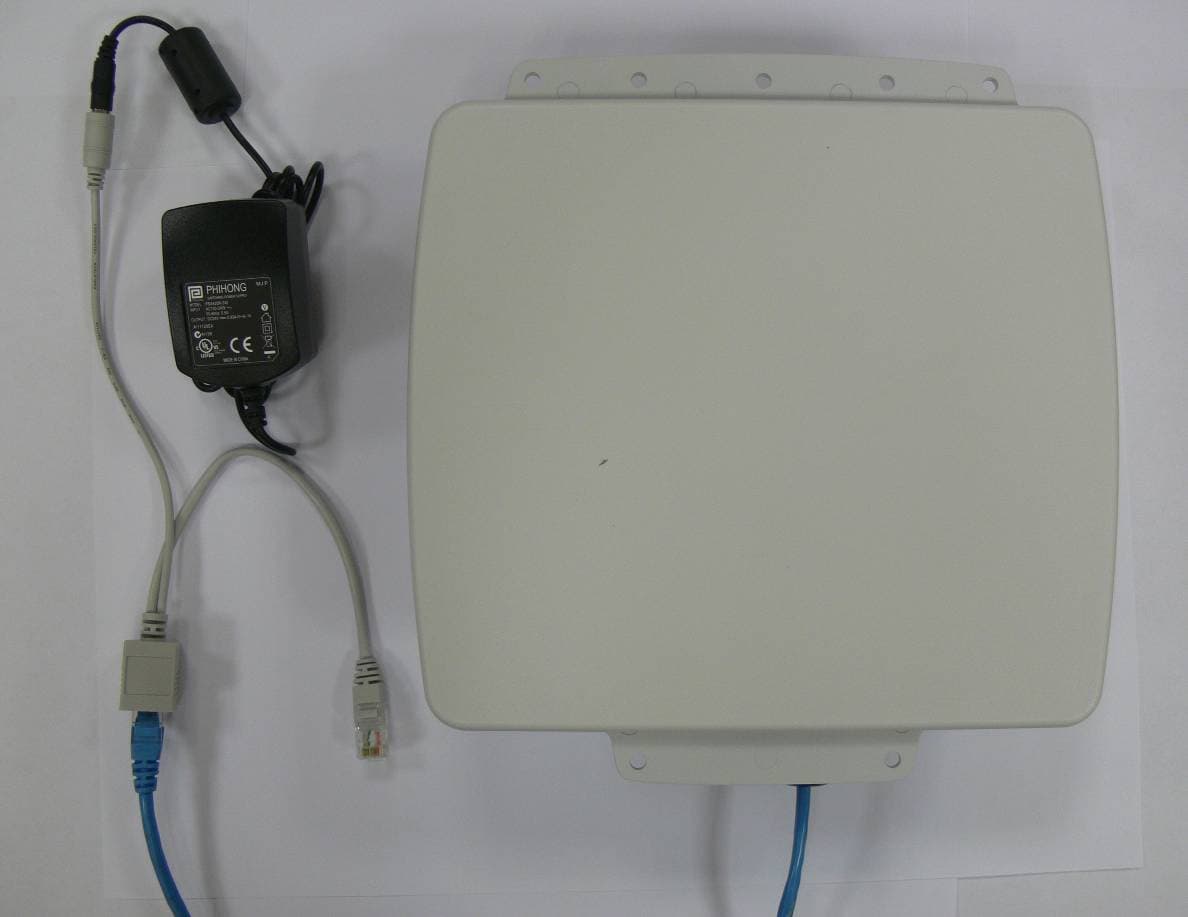
Click to zoom
Application Details
- Equipment Class
- TNB - Licensed Non-Broadcast Station Transmitter
- Date of Grant
- Jan 04, 2011
- Application Purpose
- Original Equipment
- Date of Application
- Jan 04, 2011
- Equipment Note
- 2.5 GHz TD-CDMA Outdoor Unit Transmitter
- Frequency Range
- 2501.40000000 - 2684.60000000
- Country
- United States
Documents & Files
Document Text
Text extracted from the exhibit documents filed with the FCC. Open a document above to read the original.
Users Manual
- 1 - Wireless Broadband Modem Type PEM-Outdoor (ODU) Power over Ethernet (PoE) Quick Start Guide Important Notes: 1. Complete the IPWireless Connection Software installation from the CD before you attach the PEM-ODU modem to the computer’s Ethernet port. The installation software will tell you when you should connect the modem to the Ethernet port. 2. This product is compatible with Windows versions 2000 and XP only. 3. In order for the the registration pr ocess to complete successfully, your Internet browser application must accept ‘cookies’. Browsers accept cookies by default. However, if you have disabled cookies, enable them before continuing (refer to t he Internet browser help on how to enable cookies). Safety Guidelines for the Outdoor Modem Do not attempt to disassemble the Outdoor Modem; doing so may expose you to unsafe conditions. The Outdoor Modem does not contain consumer serv iceable components. Service should be performed by the Service Provider Serv ice Center only. Contact Service Provider Customer Service to find the nearest Service Centre. Position the Outdoor Modem and accessories so that they are protected from falling objects. Do not allow liquids to spill on or into the Wireless Broadband Modem or accessories. Switch your Outdoor modem off when near medi cal equipment, fuel, chemicals, a potentially explosive atmosphere such as a gasoline station, or when in an area in which blasting is in progress. Follow any other rules, regulations, or posted notices that apply to the use of electronic or radio equipment. Before using the Outdoor modem near a pacemaker or similar device, cons ult a physician or the device manufacturer for more information. In an y event, do not use the Outdoor modem within 8" (20 cm) of a pacemaker or similar device. Do not use the Outdoor modem when you need to pay attention to other activities. For example, never use it while supervising or operating machinery. The Outdoor Modem, like any other wireless communications device, cannot guarantee a connection in all circumstances. Do not rely on it for matters where a connection is essential. Information in this document and the products described are subject to change without notice. © 2000-2009 IPWireless, Inc. All rights reserved. Reproduction, alteration, or distribution in any manner what soever without the written per mission of IPWireless, Inc. is strictly forbidden. Microsoft, Windows are registered trademarks of Microsoft Corporation. Other trademarks and trade names may be used in this docum ent to refer to either the entities claiming the marks and names, or their products. IPWireless, Inc. disclaims any proprietary inte rest in trademarks and trade names other than its own. July 2009 Part No. IPW-2041 V1 - 2 - - 7 - Getting Started This Quick Start Guide gives basic installation and c onfiguration instructions. Follow the instructions on the following pages to install the PEM-ODU Modem connection software and driver files, before connecting the modem to the computer and then performing on-line registration. Regulatory Information North America and Canada Be sure to complete each of the following steps outlined below before moving on to the next step. Your Wireless Broadband Modem may cause TV or radio interference (e.g., when using the modem in close proximity to a TV or radio rece iver). The FCC/Industry Canada can require you to stop using the modem if such interference cannot be eliminated. If the modem does cause interference with other radio communications se rvices, which can be determined by turning the equipment off and on, you are encouraged to try to correct the interference by one or more of the following measures: Step 1. Install Connection Software and Ethernet Drivers Please follow the instructions accordi ng to your installed operating system. Windows 2000™ ,Windows XP™ and Windows Vista TM - Reposition the modem’s receiving antenna. You must log in with administrative privileges - Reposition the TV or radio’s receiving antenna. 1. Close any programs that may be running and insert the CD into the CD-ROM drive on your computer. If the CD does not autorun and display a start screen, select Start- >Run and enter d:\Setup.exe where d is your CD-ROM drive letter. - Relocate the modem with respect to the TV or radio receiver. - Move the modem away from the TV or radio receiver. 2. The Installation Setup Wizard will then prom pt you through each step of the installation. (Use the Next> and < Back buttons to navigate the wizard and click Finish on the final screen). - Plug the modem into a different outlet so that the modem and the TV or radio receiver are on different branch circuits. 3. When you reach the Licence Agreement scree n, the installation will not proceed further unless you accept the terms of the License Agreement. If necessary, consult an experienced radio/tele vision technician for addi tional suggestions. You may also find the FCC Interference Handbook , 1986, to be helpful. It is available from the U.S. Government Printing Office, Washington, D.C. 20402, Stock No. 004-000-00450-7, or on the World Wide Web at http:// www.fcc.gov/Bureaus/Comp liance/WWW/tvibook.html . 4. The installation software will then copy the Connection Software and Ethernet driver files onto your computer from the installation CD. 5. When the transfer of files to the PC is complete, you will be asked to connect the Wireless Broadband Modem to the computer. This device complies with Part 15 of the FCC Rules. Operation is subject to the following two conditions: (1) this device may no t cause harmful interference, an d (2) this device must accept any interference received, including interfer ence that may cause undesired operation. Step 2. Switch on the PEM-ODU Modem Caution: Changes or modifications not covered in th is manual must be approved in writing by the Manufacturer. Changes or modifications made wi thout written approval may void the user’s authority to operate this equipment. The …
Text truncated - open the document above for the full version.
External Photos
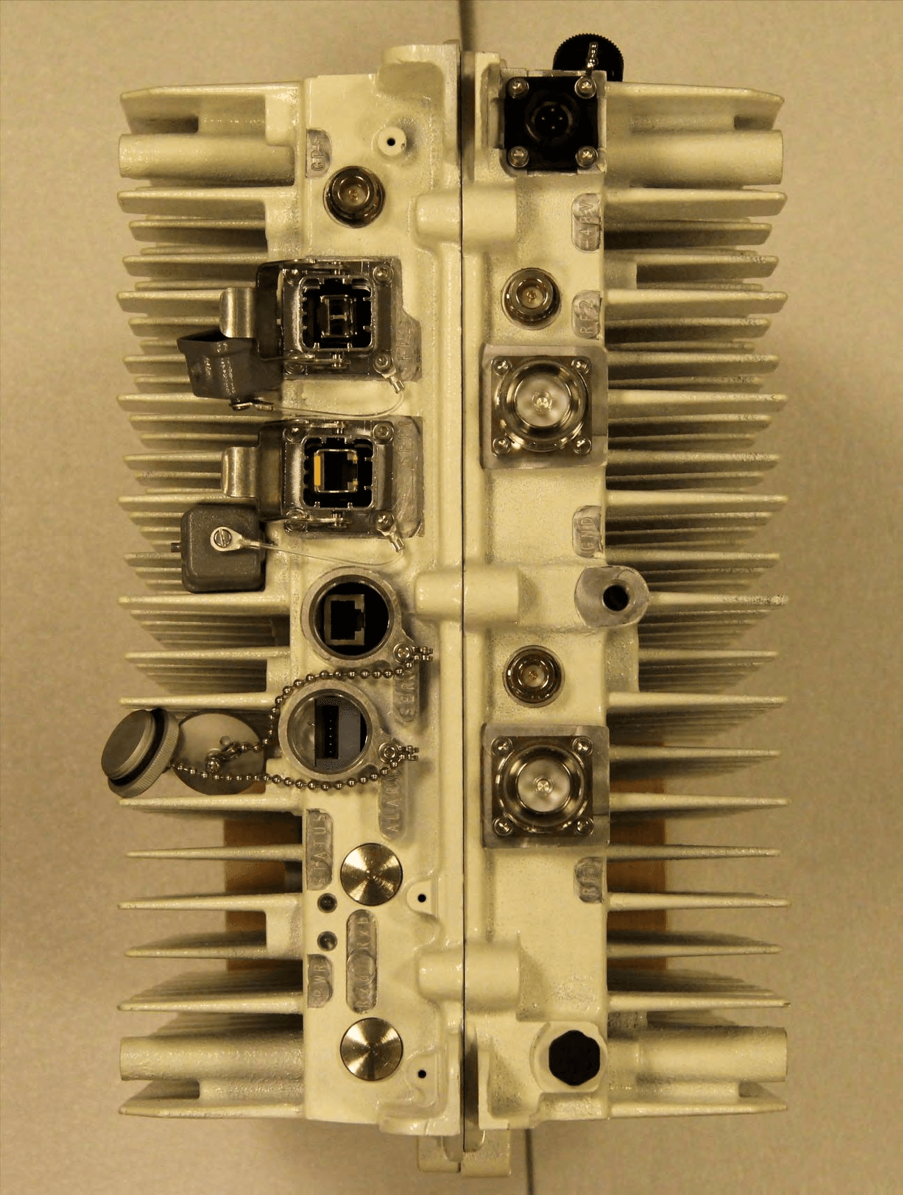
Figure 1: External Front View with Injector & PSU Figure 2: External Rear View Figure 3: External Top View Figure 4: External Left View Figure 5: External Right View Figure 6: External Bottom View
ID Label/Location Info
Figure 1: External Label Position Figure 2: External Label
Internal Photos
Figure 1: Radome Removed Figure 2: Antenna Removed Figure 3: Rear of Antenna Assembly Figure 4: PoE Adapter Board with PEM (no Lids) Figure 5: PoE Adapter Board – rear Figure 6: 2.5GHz PEM FCC ID: PKTPEMAAU1 Figure 7: Chassis Figure 1: PEM Top Shielding Removed Figure 2: PEM Bottom Shielding Removed
Test Report
TEST REPORT FROM RFI GLOBAL SERVICES LTD Test of: TD-CDMA PCI E Mini Module: AAU To: FCC Part 27: 2008 Subpart C Test Report Serial No: RFI/RPT2/RP75117JD01A Supersedes Test Report Serial No: RFI/RPT1/RP75117JD01A This Test Report Is Issued Under The Authority Of Brian Watson, Operations Director: Checked By: Nigel Davison Signature: Date of Issue: 28 August 2009 This report is issued in Adobe Acrobat portable document format (PDF). It is only a valid copy of the report if it is being viewed in PDF format with the following security options not allowed: Changing the document, Selecting text and graphics, Adding or changing notes and form fields. This report may not be reproduced other than in full, except with the prior written approval of RFI Global Services Ltd. The results in this report apply only to the sample(s) tested. TEST REPORT SERIAL NO: RFI/RPT2/RP75117JD01A ISSUE DATE: 28 AUGUST 2009 Page 2 of 66 RFI Global Services Ltd This page has been left intentionally blank. TEST REPORT SERIAL NO: RFI/RPT2/RP75117JD01A ISSUE DATE: 28 AUGUST 2009 RFI Global Services Ltd Page 3 of 66 Table of Contents 1. Customer Information .................................................................................................................. 4 2. Summary of Testing ..................................................................................................................... 5 3. Equipment Under Test (EUT) ....................................................................................................... 7 4. Operation and Monitoring of the EUT during Testing ............................................................... 9 5. Measurements, Examinations and Derived Results ................................................................ 10 6. Measurement Uncertainty .......................................................................................................... 65 Appendix 1. Test Equipment Used ................................................................................................66 TEST REPORT SERIAL NO: RFI/RPT2/RP75117JD01A ISSUE DATE: 28 AUGUST 2009 Page 4 of 66 RFI Global Services Ltd 1. Customer Information Company Name: IPWireless (UK) Ltd Address: Unit 7 Greenways Business Park Bellinger Close Chippenham Wilts SN15 1BN TEST REPORT SERIAL NO: RFI/RPT2/RP75117JD01A ISSUE DATE: 28 AUGUST 2009 RFI Global Services Ltd Page 5 of 66 2. Summary of Testing 2.1. General Information Specification Reference: 47CFR27 Specification Title: Code of Federal Regulations Volume 47 (Telecommunications) 2008: Part 27 Subpart C (Miscellaneous Wireless Communication Services) Site Registration: FCC: 209735 Location of Testing: RFI Global Services Ltd, Wade Road, Basingstoke, Hampshire, RG24 8AH. Test Dates: 03 August 2009 to 11 August 2009 2.2. Summary of Test Results FCC Reference (47CFR) Measurement Port Type Result FCC Part 15.109 Receive/Idle Mode Spurious Emissions Antenna Terminals FCC Part 2.1051 Receive/Idle Mode Conducted Spurious Emissions Main RF Port Antenna Terminals FCC Part 2.1051 Receive/Idle Mode Conducted Spurious Emissions Diversity RF Port Antenna Terminals FCC Part 2.1046, FCC Part 27.50 Transmitter Conducted Carrier Output Power Antenna Terminals FCC Part 27.54 Frequency Stability (Temperature Variation) Antenna Terminals FCC Part 27.54 Frequency Stability (Voltage Variation) Antenna Terminals FCC Part 2.1049 Occupied Bandwidth Antenna Terminals FCC Part 2.1051, FCC Part 27.53 Conducted Emissions Antenna Terminals FCC Part 2.1051, FCC Part 27.53 Radiated Spurious Emissions Enclosure Key to Results = Complied = Did not comply TEST REPORT SERIAL NO: RFI/RPT2/RP75117JD01A ISSUE DATE: 28 AUGUST 2009 Page 6 of 66 RFI Global Services Ltd 2.3. Methods and Procedures Reference: ANSI/TIA-603-C-2004 Title: Land Mobile Communications Equipment, Measurements and performance Standards Reference: ANSI C63.4 (2003) Title: American National Standard Methods of Measurement of Electromagnetic Emissions from Low Voltage Electrical and Electronic Equipment in the Range of 9 kHz to 40 GHz. 2.4. Deviations from the Test Specification Testing at voltage extremes was carried out at V nom and V nom ±9% at the request of the Customer and not Vnom and Vnom ±15% as required by the Standard. This is because the EUT complies with the PCI Express Standard which specifies the ±9% tolerance. A breakout point for the power supply was provided by the Customer on adapter board (Serial No. EEMS 022630 0004) in order to vary the supply to the EUT as this is normally provided from the PCI Express interface on the standard adapter board (Serial No. AAFK85100G240). TEST REPORT SERIAL NO: RFI/RPT2/RP75117JD01A ISSUE DATE: 28 AUGUST 2009 RFI Global Services Ltd Page 7 of 66 3. Equipment Under Test (EUT) 3.1. Identification of Equipment Under Test (EUT) Description: TD-CDMA PCI-E Mini Module Brand Name: IPWireless Model Name or Number: AAU Serial Number: AAUA930000D37 IMEI Number: 357163020001207 Hardware Version Number: Version 1 Software Version Number: None Stated FCC ID Number: PKTPEMAAU1 3.2. Description of EUT The equipment under test was a PCI-E mini module. 3.3. Modifications Incorporated in the EUT No modifications were applied to the EUT during testing. 3.4. Additional Information Related to Testing Power Supply Requirement: 3.3V DC ± 9% Equipment Category: Module Type of Unit: PCI Express mini module Chip Rate: 3.84 Mcps Declared Channel Bandwidth: 5.5 MHz Duty Cycle: 80% Highest generated frequency: 3.6 GHz Antenna Gain: +9 dBi (stated) Transmit Frequency Range: 2496 MHz to 2690 MHz Channel ID Channel Number Channel Frequency (MHz) Bottom 12494 2498.8 Middle 12965 2593.0 Transmit Channels Tested: Top 13436 2687.2 Receive Frequency Range: 2496 MHz to 2690 MHz Channel ID Channel Number Channel Frequency (MHz) Bottom 12494 2498.8 Middle 12965 2593.0 Receive Channels Tested: Top 13436 2687.2 TEST REPORT SERIAL NO: RFI/RPT2/RP75117JD01A ISSUE DATE: 28 AUGUST 2009 Page 8 of 66 RFI Global Serv…
Text truncated - open the document above for the full version.
Test Report
TEST REPORT FROM RFI GLOBAL SERVICES LTD Test of: TD-CDMA PCI-E Mini Module, Model: AAU To: FCC Part 27: 2008 Subpart C Test Report Serial No: RFI/RPT2/RP75541JD01A Supersedes Test Report Serial No: RFI/RPT1/RP75541JD01A This Test Report Is Issued Under The Authority Of Brian Watson, Operations Director: Checked By: Nigel Davison Signature: Date of Issue: 28 August 2009 This report is issued in Adobe Acrobat portable document format (PDF). It is only a valid copy of the report if it is being viewed in PDF format with the following security options not allowed: Changing the document, Selecting text and graphics, Adding or changing notes and form fields. This report may not be reproduced other than in full, except with the prior written approval of RFI Global Services Ltd. The results in this report apply only to the sample(s) tested. TEST REPORT SERIAL NO: RFI/RPT2/RP75541JD01A ISSUE DATE: 28 AUGUST 2009 Page 2 of 66 RFI Global Services Ltd This page has been left intentionally blank. TEST REPORT SERIAL NO: RFI/RPT2/RP75541JD01A ISSUE DATE: 28 AUGUST 2009 RFI Global Services Ltd Page 3 of 66 Table of Contents 1. Customer Information .................................................................................................................. 4 2. Summary of Testing ..................................................................................................................... 5 3. Equipment Under Test (EUT) ....................................................................................................... 7 4. Operation and Monitoring of the EUT during Testing ............................................................... 9 5. Measurements, Examinations and Derived Results ................................................................ 10 6. Measurement Uncertainty .......................................................................................................... 65 Appendix 1. Test Equipment Used ................................................................................................66 TEST REPORT SERIAL NO: RFI/RPT2/RP75541JD01A ISSUE DATE: 28 AUGUST 2009 Page 4 of 66 RFI Global Services Ltd 1. Customer Information Company Name: IPWireless (UK) Ltd Address: Unit 7 Greenways Business Park Bellinger Close Chippenham Wilts SN15 1BN TEST REPORT SERIAL NO: RFI/RPT2/RP75541JD01A ISSUE DATE: 28 AUGUST 2009 RFI Global Services Ltd Page 5 of 66 2. Summary of Testing 2.1. General Information Specification Reference: 47CFR27 Specification Title: Code of Federal Regulations Volume 47 (Telecommunications) 2008: Part 27 Subpart C (Miscellaneous Wireless Communication Services) Site Registration: FCC: 209735 Location of Testing: RFI Global Services Ltd, Wade Road, Basingstoke, Hampshire, RG24 8AH. Test Dates: 03 August 2009 to 11 August 2009 2.2. Summary of Test Results FCC Reference (47CFR) Measurement Port Type Result FCC Part 15.109 Receive/Idle Mode Spurious Emissions Antenna Terminals FCC Part 2.1051 Receive/Idle Mode Conducted Spurious Emissions Main RF Port Antenna Terminals FCC Part 2.1051 Receive/Idle Mode Conducted Spurious Emissions Diversity RF Port Antenna Terminals FCC Part 2.1046, FCC Part 27.50 Transmitter Conducted Carrier Output Power Antenna Terminals FCC Part 27.54 Frequency Stability (Temperature Variation) Antenna Terminals FCC Part 27.54 Frequency Stability (Voltage Variation) Antenna Terminals FCC Part 2.1049 Occupied Bandwidth Antenna Terminals FCC Part 2.1051, FCC Part 27.53 Conducted Emissions Antenna Terminals FCC Part 2.1051, FCC Part 27.53 Radiated Spurious Emissions Enclosure Key to Results = Complied = Did not comply TEST REPORT SERIAL NO: RFI/RPT2/RP75541JD01A ISSUE DATE: 28 AUGUST 2009 Page 6 of 66 RFI Global Services Ltd 2.3. Methods and Procedures Reference: ANSI/TIA-603-C-2004 Title: Land Mobile Communications Equipment, Measurements and performance Standards Reference: ANSI C63.4 (2003) Title: American National Standard Methods of Measurement of Electromagnetic Emissions from Low Voltage Electrical and Electronic Equipment in the Range of 9 kHz to 40 GHz. 2.4. Deviations from the Test Specification Testing at voltage extremes was carried out at V nom and V nom ±9% at the request of the customer and not Vnom and Vnom ±15% as required by the Standard. This is because the EUT complies with the PCI Express Standard which specifies the ±9% tolerance. A breakout point for the power supply was provided by the customer on adapter board (Serial No. EEMS 022630 0004) in order to vary the supply to the EUT as this is normally provided from the PCI Express interface on the standard adapter board (Serial No. AAFK85100G240). TEST REPORT SERIAL NO: RFI/RPT2/RP75541JD01A ISSUE DATE: 28 AUGUST 2009 RFI Global Services Ltd Page 7 of 66 3. Equipment Under Test (EUT) 3.1. Identification of Equipment Under Test (EUT) Description: TD-CDMA PCI-E Mini Module Brand Name: IPWireless Model Name or Number: AAU Serial Number: AAUA930000D37 IMEI Number: 357163020001207 Hardware Version Number: Version 1 Software Version Number: None Stated FCC ID Number: PKTPEMAAU1 3.2. Description of EUT The equipment under test was a PCI-E mini-module. 3.3. Modifications Incorporated in the EUT No modifications were applied to the EUT during testing. 3.4. Additional Information Related to Testing Power Supply Requirement: 3.3 V DC ± 9% Equipment Category: Module Type of Unit: PCI Express mini module Chip Rate: 7.68 Mcps Declared Channel Bandwidth: 11 MHz Duty Cycle: 80% Highest generated frequency: 3.6 GHz Antenna Gain: +9 dBi (stated) Transmit Frequency Range: 2496 MHz to 2690 MHz Channel ID Channel Number Channel Frequency (MHz) Bottom 12507 2501.4 Middle 12965 2593.0 Transmit Channels Tested: Top 13420 2684.6 Receive Frequency Range: 2496 MHz to 2690 MHz Channel ID Channel Number Channel Frequency (MHz) Bottom 12507 2501.4 Middle 12965 2593.0 Receive Channels Tested: Top 13420 2684.6 TEST REPORT SERIAL NO: RFI/RPT2/RP75541JD01A ISSUE DATE: 28 AUGUST 2009 Page 8 of 66 RFI Glob…
Text truncated - open the document above for the full version.
Test Report
Reviewed by: FCC ID: PKTODUAFD1 FCC Pt. 27 QPSK, 16-QAM, 64-QAM MEASUREMENT REPORT (CERTIFICATION) Quality Manager Test Report S/N: Test Dates: EUT Type: 0Y1011101835.PKT Dec. 1-9, 2010 Outdoor Directional User Equipment Page 1 of 48 © 2010 PCTEST Engineering Laboratory, Inc. REV 1.7AWSC 12/10/09 Applicant Name: Date of Testing: IP Wireless Dec. 1-9, 2010 Unit 7 Greenways Business Park Test Site/Location: Bellinger Close, Chippenham PCTEST Lab., Columbia, MD, USA Wiltshire SN15 1BN Test Report Serial No.: 0Y1011101835.PKT FCC ID: PKTODUAFD1 APPLICANT: IP WIRELESS Application Type: Certification FCC Classification: Licensed Non-Broadcast Station Transmitter (TNB) FCC Rule Part(s): §2; §27 EUT Type: Outdoor Directional User Equipment Model(s): AFD Tx Frequency Range: 2496-2690 MHz Max. RF Output Power: 7.798 W EIRP (2498.8 MHz at 3.84Mcps 16-QAM) (38.92 dBm) 7.551 W EIRP (2593 MHz at 3.84Mcps QPSK) (38.78 dBm) 5.623 W EIRP (2687.2 MHz at 3.84Mcps 16-QAM) (37.5 dBm) 6.714 W EIRP (2501.4 MHz at 7.68Mcps QPSK) (38.27 dBm) 9.354 W EIRP (2593 MHz at 7.68Mcps 16-QAM) (39.71 dBm) 8.035 W EIRP (2684.6 MHz at 7.68Mcps 16-QAM) (39.05 dBm) Test Device Serial No.: identical prototype [S/N: N/A] This equipment has been shown to be capable of compliance with the applicable technical standards as indicated in the measurement report and was tested in accordance with the measurement procedures specified in §2.947. Test results reported herein relate only to the item(s) tested. I attest to the accuracy of data. All measurements reported herein were performed by me or were made under my supervision and are correct to the best of my knowledge and belief. I assume full responsibility for the completeness of these measurements and vouch for the qualifications of all persons taking them. Grant Conditions: Power output listed is EIRP for Part 27. PCTEST certifies that no party to this application has been subject to a denial of Federal benefits that includes FCC benefits pursuant to Section 5301 of the Anti-Drug Abuse Act of 1988, 21 U.S.C. 862. PCTEST ENGINEERING LABORATORY, INC. 6660-B Dobbin Road, Columbia, MD 21045 USA Tel. 410.290.6652 / Fax 410.290.6554 http://www.pctestlab.com MEASUREMENT REPORT FCC Part 27 Reviewed by: FCC ID: PKTODUAFD1 FCC Pt. 27 QPSK, 16-QAM, 64-QAM MEASUREMENT REPORT (CERTIFICATION) Quality Manager Test Report S/N: Test Dates: EUT Type: 0Y1011101835.PKT Dec. 1-9, 2010 Outdoor Directional User Equipment Page 2 of 48 © 2010 PCTEST Engineering Laboratory, Inc. REV 1.7AWSC 12/10/09 TABLE OF CONTENTS FCC PART 27 MEASUREMENT REPORT..................................................................................3 1.0 INTRODUCTION....................................................................................................................4 1.1 SCOPE..................................................................................................................................................................4 1.2 TESTING FACILITY............................................................................................................................................4 2.0 PRODUCT INFORMATION.....................................................................................................5 2.1 EQUIPMENT DESCRIPTION...........................................................................................................................5 2.2 EMI SUPPRESSION DEVICE(S)/MODIFICATIONS....................................................................................5 2.3 LABELING REQUIREMENTS...........................................................................................................................5 3.0 DESCRIPTION OF TESTS......................................................................................................6 3.1 MEASUREMENT PROCEDURE......................................................................................................................6 3.2 2496-2690 MHZ BAND.......................................................................................................................................6 3.3 RADIATED POWER AND RADIATED SPURIOUS EMISSIONS...............................................................6 4.0 TEST EQUIPMENT CALIBRATION DATA...............................................................................7 5.0 SAMPLE CALCULATIONS......................................................................................................8 6.0 TEST RESULTS.....................................................................................................................9 6.1 SUMMARY...........................................................................................................................................................9 6.2 EQUIVALENT ISOTROPIC RADIATED POWER OUTPUT DATA..........................................................10 6.3 TD-CDMA RADIATED MEASUREMENTS FOR CHANNEL EDGE.........................................................12 6.4 TD-CDMA RADIATED SPURIOUS MEASUREMENTS.............................................................................30 7.0 CONCLUSION.....................................................................................................................48 Reviewed by: FCC ID: PKTODUAFD1 FCC Pt. 27 QPSK, 16-QAM, 64-QAM MEASUREMENT REPORT (CERTIFICATION) Quality Manager Test Report S/N: Test Dates: EUT Type: 0Y1011101835.PKT Dec. 1-9, 2010 Outdoor Directional User Equipment Page 3 of 48 © 2010 PCTEST Engineering Laboratory, Inc. REV 1.7AWSC 12/10/09 MEASUREMENT REPORT FCC Part 27 §2.1033 General Information APPLICANT: IP Wireless APPLICANT ADDRESS: Unit 7 Greenways Business Park Bellinger Close, Chippenham, Wiltshire SN15 1BN TEST SITE: PCTEST ENGINEERING LABORATORY, INC. TEST SITE ADDRESS: 6660-B Dobbin Road, Columbia, MD 21045 USA FCC RULE PART(S): §2; §27 BASE MODEL: AFD FCC ID: PKTODUAFD1 FCC CLASSIFICATION: Licensed Non-Broadcast Station Transmitter (TNB) MODULATIONS: QPSK, 16-QAM, 64-…
Text truncated - open the document above for the full version.
Test Setup Photos
IP Wireless FCC ID: PKTODUAFD1 Model: AFD Test Set-Up Photos EUT Type: Outdoor Directional User Equipment Page 1 of 1 © 2010 PCTEST Engineering Laboratory Inc. TEST SETUP PHOTOGRAPHS IP Wireless FCC ID: PKTODUAFD1 Model: AFD Test Set-Up Photos EUT Type: Outdoor Directional User Equipment Page 2 of 2 © 2010 PCTEST Engineering Laboratory Inc.
Contact Information
Applicant
Joseph Cheung
Technical Contact
PCTEST Engineering Laboratory, Inc.Randy Ortanez
[email protected]410-290-6652
6660-B Dobbin Road · Columbia, Maryland · United States
Test Firm
PCTEST Engineering Laboratory, Inc.Randy Ortanez
Technical Specifications
| # | Rule Parts | Frequency Range | Power Output | Emission | Tolerance |
|---|---|---|---|---|---|
| 4 | 27 | 2.50 GHz - 2.68 GHz | 9.35 W | 8M40D7W | 1 ppm |
Other Applications from General Dynamics Broadband, Inc.
PKTNODEBAZY
Oct 21, 2015Band 12 LTE Base Station
Equipment Class
TNB - Licensed Non-Broadcast Station Transmitter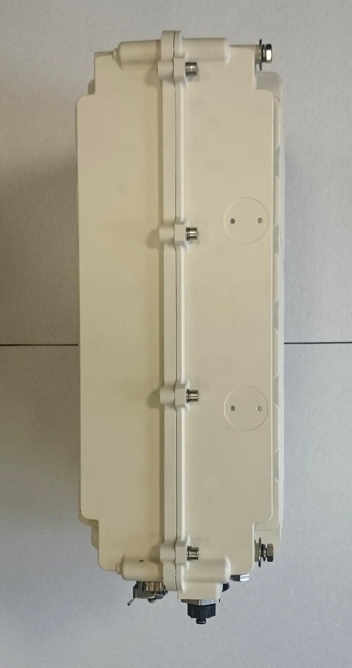
PKTNODEBBBK
Mar 23, 2015Band 14 LTE Base Station
Equipment Class
TNB - Licensed Non-Broadcast Station Transmitter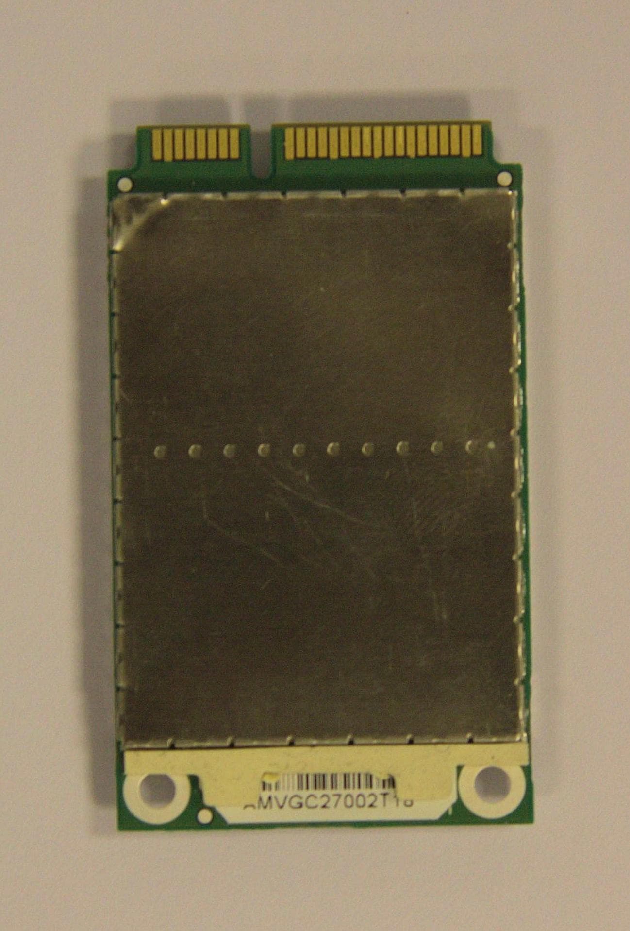
PKTPEMAMW1
Apr 03, 2014Broadband PCI Express Mini Module
Equipment Class
TNB - Licensed Non-Broadcast Station Transmitter
PKTUSBSTKARM
Dec 02, 2012LTE Band 12 USB Stick Modem
Equipment Class
TNB - Licensed Non-Broadcast Station Transmitter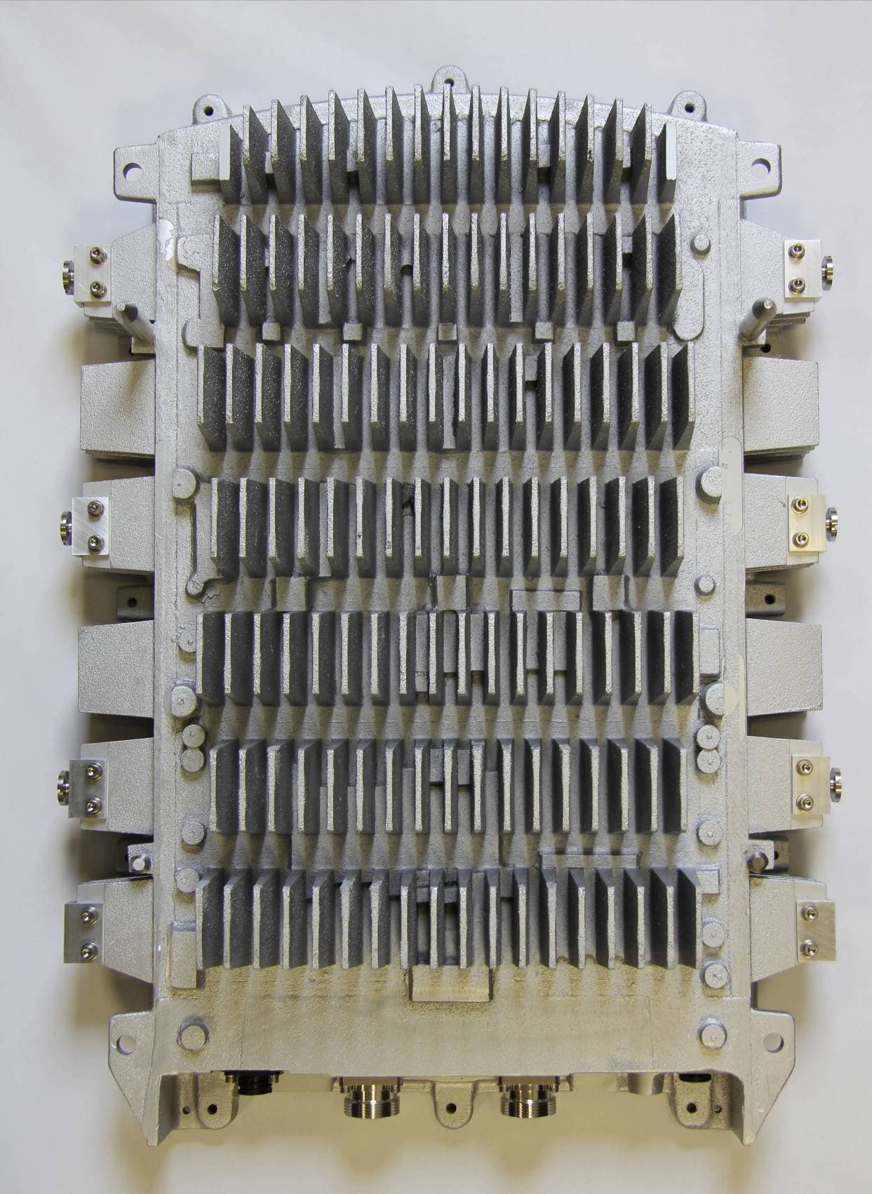
PKTNODEBAQQ
Oct 03, 20123GPP Band 12 LTE Base Station
Equipment Class
TNB - Licensed Non-Broadcast Station Transmitter