PKTP1BAP1Broadband Modem, Model AP
General Dynamics Broadband, Inc.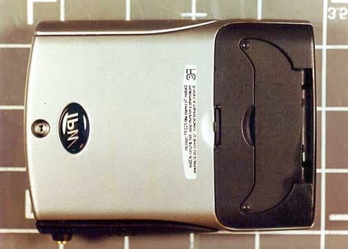
Click to zoom
Application Details
- Equipment Class
- TNB - Licensed Non-Broadcast Station Transmitter
- Date of Grant
- Jan 30, 2002
- Application Purpose
- Original Equipment
- Date of Application
- Jan 30, 2002
- Equipment Note
- Broadband Modem, Model AP
- Frequency Range
- 2500.00000000 - 2686.00000000
- Country
- United States
Documents & Files
Document Text
Text extracted from the exhibit documents filed with the FCC. Open a document above to read the original.
Users Manual
IPWireless Broadband Mode m User Guide 1 IPWireless Broadband Modem 1B User Guide Version 1.0 June 29, 2001 IPWireless Broadband Mode m User Guide 2 Information in this document and the products described are subject to change without notice. © 2000-2001 IPWireless, Inc. All rights reserved. Reproduction, alteration, or distribution in any manner whatsoever without the written permission of IPWireless Inc., is strictly forbidden. Trademarks used in this text: the IPWireless logo, icon, and IPWireless Broadband Modem are trademarks of IPWireless, Inc.; Microsoft, Windows, and Windows NT are registered trademarks of Microsoft Corporation. Other trademarks and trade names may be used in this document to refer to either the entities claiming the marks and names or their products. IPWireless, Inc., disclaims any proprietary interest in trademarks and trade names other than its own. December 2001Part No. IPW-0029 IPWireless Broadband Mode m User Guide 3 Table of Contents Introduction ........................................................................................................................................5 Technical Support.............................................................................................................................................5 Chapter 1 – Safety and Care Instructions .............................................................6 Safety Guidelines for Power Connection.........................................................................................................6 Safety Guidelines for the IPWireless Broadband Modem................................................................................6 Exposure to Radio Frequency Signals..............................................................................................................7 Care and Cleaning Guidelines..........................................................................................................................8 Chapter 2 - Getting Started .................................................................................................9 Required Equipment.........................................................................................................................................9 Package Contents..............................................................................................................................................9 Computer Interface Cable.................................................................................................................................9 AC Power Adapter...........................................................................................................................................9 Installation CD..................................................................................................................................................9 Other Informational Material...........................................................................................................................9 Key Areas on Your IPWireless Broadband Modem......................................................................................10 Chapter 3 – Installation and Registration ...........................................................12 Support the IPWireless Broadband Modem Using the Built-in Stand...........................................................12 Connect the AC Power Adapter.....................................................................................................................13 Find the Best Radio Signal.............................................................................................................................13 Install the IPWireless PC Software................................................................................................................15 Cable Connection between the Modem and the Computer............................................................................19 USB Cable Connection...................................................................................................................................20 RS-232 Serial Cable Connection....................................................................................................................20 Perform Registration.......................................................................................................................................22 Adobe Acrobat Reader Installation................................................................................................................24 Window s Operati ng S yste m Patc hes..............................................................................................................24 Windows Internet Configuration Setting........................................................................................................24 Chapter 3 – Connect to the Internet .........................................................................26 Establishing the Connection to the Internet....................................................................................................28 IPWireless Broadband Mode m User Guide 4 Appendix A – Troubleshooting Tips .........................................................................30 Troubleshooting Tips......................................................................................................................................30 T HE P OWER BUTTON IS ON BUT THE DISPLAY DOES NOT ILLUMINATE ...............................................30 N O S IGNAL R ING INDICATORS ARE ILLUMINATED ON THE IPW IRELESS B ROADBAND M ODEM DISPLAY .........................................................................................................................................................30 O NLY ONE OR TWO SIGNAL STRENGTH RINGS ARE ILLUMINATED .......................................................31 T HE IPW IRELESS B ROADBAND M ODEM DISCONNECTS UNEXPECTEDLY ............…
Text truncated - open the document above for the full version.
Cover Letter(s)
1250 Bayhill Drive, Suite 113 San Bruno CA 94066 U.S.A. Tel: +44 (0) 1249 705 400 Fax: +44 (0) 1249 705 401 IPWireless UK Limited Registered Office: 4 Lansdowne Court, Bumpers Way, Chippenham SN14 6RZ Registered in England No. 4218312 14 th December 2001 Federal Communicatio ns Commission 7435 Oakland Mills Road Columbia MD 21046 Dear Sir/Madam RE: Confidentiality Request This letter is to comply with Sectio n 0.457(d)(2)(i) pertaining to confidential material. IPWireless Inc. would like the following documents regarding this submission for FCC ID: { type your ID number} to be kept co nfidential. 1. All Schematics. 2. All pages of file: UE1BRAD.DOC. The above material co ntains trade secrets or technical data, which would customarily be guarded from competitors. We do not want these documents to be accessible to the general public. Yo urs Sinc ere ly, Lamech Mujegu Technical Director
ID Label/Location Info
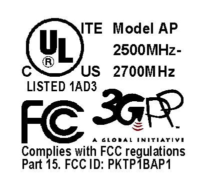
FCC ID: PKTP1BAP1 FCC ID: PKTP1BAP1
Parts List/Tune Up Info
This device is set at the factory, there is no tune-up procedure.
RF Exposure Info
1250 Bayhill Drive, Suite 113 San Bruno CA 94066 U.S.A. Tel: +44 (0) 1249 705 400 Fax: +44 (0) 1249 705 401 IPWireless UK Limited Registered Office: 4 Lansdowne Court, Bumpers Way, Chippenham SN14 6RZ Registered in England No. 4218312 14 th December 2001 Federal Communicatio ns Commission 7435 Oakland Mills Road Columbia MD 21046 Dear Sir/Madam RE: Maximum Permissible Exposure (MPE) for the IPWireless Broadband Modem Model No: AP The FCC identification number for this device is PKTP1BAP. Background The IPWireless Inc. broadband wireless modem Model No: AP is intended for connection to a perso nal computer, this can either be a desktop or laptop computer. Under rule 2.1091 section (d) subsection (4) the operating conditions of the device make classification as either portable or mobile difficult. To provide information to ensure the device is used in a safe manner, the minimum separatio n distance from the radiating structure of the device to the user or any other person has been calculated based o n the MPE limits for the general populatio n/unco ntrolled exposure category. The calculations belo w take into account the worst case normal operation of the device i.e. the user is using the f ull data bandwidth of the device. The RF interface operates using a time division duplex implementation whereby the modem transmits using 4 o ut of a total of 15 timeslots in a radio frame. This provides good justification for using source based averaging of the transmitter power as defined in rule 2.1091 section (d) subsection (2). Applicable Limits to RF Exposure The RF exposure limits for radio transmitters are established in 47CFR1.1310. These limits are established for different frequency ranges and the type of enviro nment the device is expected to be used in. For the IPWireless Inc. broadband wireless modem Model No. AP, the applicable power density limit is given in Table 1 part (b) as: 1 mW/cm 2 (general populatio n, unco ntrolled exposure) Model AP Device Parameters used in MPE Calculation The Model AP has a maximum conducted output power to the antenna of +24dBm, the integral antenna gain is 3 dBi, providing a maximum EIRP of +27dBm. This emission is spread over 1 MHz of channel bandwidth, providing a maximum power level of +24dBm in a 6MHz MMDS channel. This unit is being qualified under the low power respo nse station rules contained in both 47CFR21.908 (d) and 47CFR74.936 (f), which defines the maximum transmitter power limit of –6dBW EIRP in a 6MHz channel. This device operates in a 12 MHz channel and as such, the maximum EIRP allowed is –6dBW + 3dB = -3dBW EIRP. The maximum EIRP of the modem using the integral antenna is as follows: EIRP =+24dBm + 3dB (ant. gain) =+27dBm =-3dBW Therefore the EIRP complies with the –3 dBW limit allowed for a 12 MHz bandwidth emission for a low po wer response statio n. Distance to Power Density Limit Calculation For the purpose of calculating the MPE distance from the Model AP antenna, the –3 dBW (+27 dBm) EIRP value is used. The formula used to calculate the distance to the 1mW/cm2 limit is defined in FCC Bulletin 65. S = PG Equatio n (1) 4 R 2 Equatio n (1) is re-arranged to calculated distance R. R = PG Equatio n (2) 4 S Where:S= Power Density Limit of 1mW/cm2 P= Transmitter Power G= Numerical Antenna Gain The table below sho ws the calculatio n of the distance from the antenna to the 1mW/cm2 limit for the general populatio n/unco ntrolled exposure limit. MPE distance calculation for PKTP1BAP Integral Antenna gain3dBi line loss0dB Effective antenna gain (ratio)1.99 Model AP PA conducted output power24dBm 27dBmModel AP maximum EIRP 501mW Model AP maximum EIRP-3dBW 21.908 (d) EIRP limit in 12 MHz bandwidth-3dBW MPE limit from 1.1310, MMDS band 1 mW/cm 2 (general population, uncontrolled exposure) minimum distance = sqrt ((EIRP/(exposure limit*4*pi)) Minimum distance to meet MPE limit = 6.32cm (without source-based averaging)2.49inches Source-based duty cycle adjustment Total timeslots in frame15 Timeslots used for uplink transmit4 Percent of uplink time device is transmitting100% Average attenuation of signal (power control)0dB Minimum distance to meet MPE limit = 3.26cm (with source-based averaging) 1.28inches Conclusion The table above shows the device meets the 1mW/cm 2 exposure limit at a distance 1.28 inches from the integral antenna during worst case normal operation. In accordance with rules 1.1307 table 1 and 2.1091 section (d) subsectio n (4) the minimum separation distance of 1 inch will be identified on the label placed on the unit. Additionally, the user manual provides instructions to the user to ensure operation of the device in a safe manner. Yo urs Sinc ere ly, Lamech Mujegu Technical Director
Test Report
Page 1 of 56 Report No.: FC01-086 IPWIRELESS, INC. TEST REPORT FOR THE BROADBAND MODEM, MODEL AP FCC PART 21 SUBPART K & FCC PART 15 SUBPART B SECTIONS 15.107 & 15.109 CLASS B COMPLIANCE DATE OF ISSUE: JANUARY 11, 2002 PREPARED FOR: IPWireless, Inc. 1001 Bayhill Drive, Second Floor San Bruno, CA 94066 PREPARED BY: Joyce Walker CKC Laboratories, Inc. 5473A Clouds Rest Mariposa, CA 95338 P.O. No.: UK1175/2001 W.O. No.: 78019 Date of test: November 19 - December 9, 2001 Report No.: FC01-086 This report contains a total of 56 pages and may be reproduced in full only. Partial reproduction may only be done with the written consent of CKC Laboratories, Inc. Page 2 of 56 Report No.: FC01-086 TABLE OF CONTENTS Administrative Information ............................................................................................. 3 Summary of Results......................................................................................................... 4 Modifications Required for Compliance ......................................................................... 4 Approvals......................................................................................................................... 4 Equipment Under Test (EUT) Description...................................................................... 5 Equipment Under Test..................................................................................................... 5 Peripheral Devices ........................................................................................................... 5 Temperature and Humidity During Testing .................................................................... 6 2.1033(c)(3) User’s Manual ............................................................................................ 6 2.1033(c)(4) Type of Emissions ...................................................................................... 6 2.1033(c)(5) Frequency Range ........................................................................................ 6 2.1033(c)(6) Operating Power ......................................................................................... 6 2.1033(c)(7) Maximum Power Rating............................................................................. 7 2.1033(c)(8) DC Voltages ............................................................................................... 7 2.1033(c)(9) Tune-Up Procedure .................................................................................... 7 2.1033(c)(10) Schematics and Circuitry Description ...................................................... 7 2.1033(c)(11) Label and Placement................................................................................. 7 2.1033(c)(12) Submittal Photos....................................................................................... 8 2.1033(c)(13) Modulation Information ........................................................................... 8 2.1033(c)(14)/2.1046/21.904(e) RF Power Output & 2.1033(c)(14)/2.1049(i)/21.908(d) Occupied Bandwidth................................................ 9 FCC Channel Requirements ................................................................................ 10 Canada Channel Requirements............................................................................ 11 Occupied Bandwidth - Low................................................................................. 12 Occupied Bandwidth - Middle ............................................................................ 13 Occupied Bandwidth - High ................................................................................ 14 Out Of Band Spurious - Low............................................................................... 15 Out Of Band Spurious - Middle .......................................................................... 16 Out Of Band Spurious - High .............................................................................. 17 2.1033(c)(14)/2.1047(b) - Modulation Characteristics - Audio Frequency Response .... 18 2.1033(c)(14)/2.1047(b) - Modulation Characteristics - Modulation Limiting Response..... 18 2.1033(c)(14)/2.1051/21.908(d) - Spurious Emissions at Antenna Terminal ................. 19 2.1033(c)(14)/2.1053/21.908(d) - Field Strength of Spurious Radiation ........................ 27 2.1033(c)(14)/2.1055/21.101 - Frequency Stability ........................................................ 37 15.107 – AC Conducted Emissions - Receiver ............................................................... 40 15.109 – Radiated Emissions - Receiver ......................................................................... 47 Page 3 of 56 Report No.: FC01-086 CKC Laboratories, Inc. has received Certificates of Accreditation from the following agencies: A2LA (USA); DATech (Germany); BSMI (Taiwan); Nemko (Norway); and GOST (Russia). CKC Laboratories, Inc has received test site Registration Acceptance from the following agencies: FCC (USA); VCCI (Japan); and Industry Canada. CKC Laboratories, Inc. has received Letters of Acceptance through an MRA for the following agencies: ACA/NATA (Australia); SABS (South Africa); SWEDAC (Sweden); Radio Communications Agency (RA); HOKLAS (Hong Kong); Bakom (Swiss); BIPT (Belgium); Denmark Telestyrelsen; RvA (Netherlands); SEE (Luxembourg) SITTEL (Bolivia); and UKAS (UK). ADMINISTRATIVE INFORMATION DATE OF TEST: November 19 - December 9, 2001 DATE OF RECEIPT: November 19, 2001 PURPOSE OF TEST: To demonstrate the compliance of the Broadband Modem, Model AP with the requirements for FCC Part 21 Subpart K and FCC Part 15 Subpart B Sections 15.107 and 15.109 Class B devices. TEST METHOD: ANSI C63.4 (1992) and FCC Part 21 MANUFACTURER: IPWireless, Inc. 1001 Bayhill Drive, Second Floor San Bruno, CA 94066 REPRESENTATIVE: Peter Warburg TEST LOCATION: CKC Laboratories, Inc. 480 Los Viboras Road Hollister, CA 95023 5473A Clouds Rest Mariposa, CA 95338 Page 4 of 56 Report…
Text truncated - open the document above for the full version.
Test Setup Photos
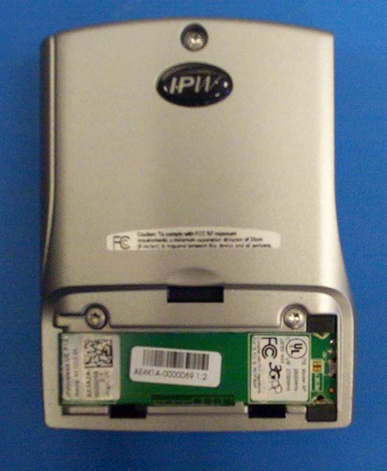
RF Output and Occupied Bandwidth Test Setup Spurious Emissions Test Setup Field Strength Test Setup – Front View Field Strength Test Setup – Back View Frequency Stability Test Setup Mains Conducted Emissions Test Setup - Front View Mains Conducted Emissions Test Setup - Side View Field Strength Test Setup – Front view Field Strength Test Setup – Back View
Contact Information
Applicant
Joseph Cheung
Technical Contact
CKC Laboratories, Inc.Joyce Walker
[email protected]800-500-4362
5473A Clouds Rest · Mariposa, California · United States
Non-Technical Contact
CKC Laboratories, Inc.Joyce Walker
[email protected]800-500-4362
Test Firm
CKC Laboratories, Inc.Steve Behm
Technical Specifications
| # | Rule Parts | Frequency Range | Power Output | Emission | Tolerance |
|---|---|---|---|---|---|
| 2 | 74 | 2.50 GHz - 2.69 GHz | 240.00 mW | 12M0G7D | 4000 Hz |
Other Applications from General Dynamics Broadband, Inc.
PKTNODEBAZY
Oct 21, 2015Band 12 LTE Base Station
Equipment Class
TNB - Licensed Non-Broadcast Station Transmitter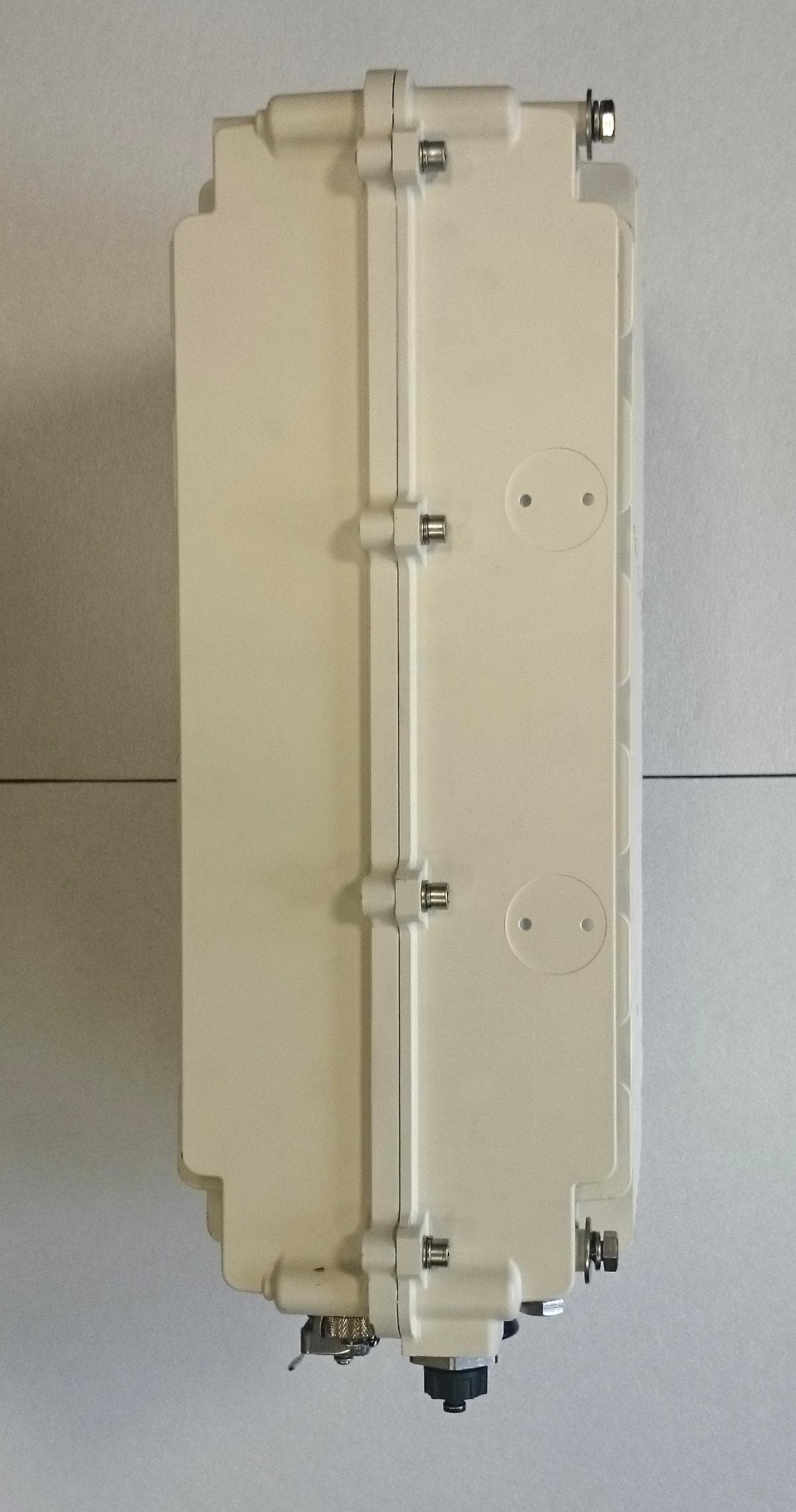
PKTNODEBBBK
Mar 23, 2015Band 14 LTE Base Station
Equipment Class
TNB - Licensed Non-Broadcast Station Transmitter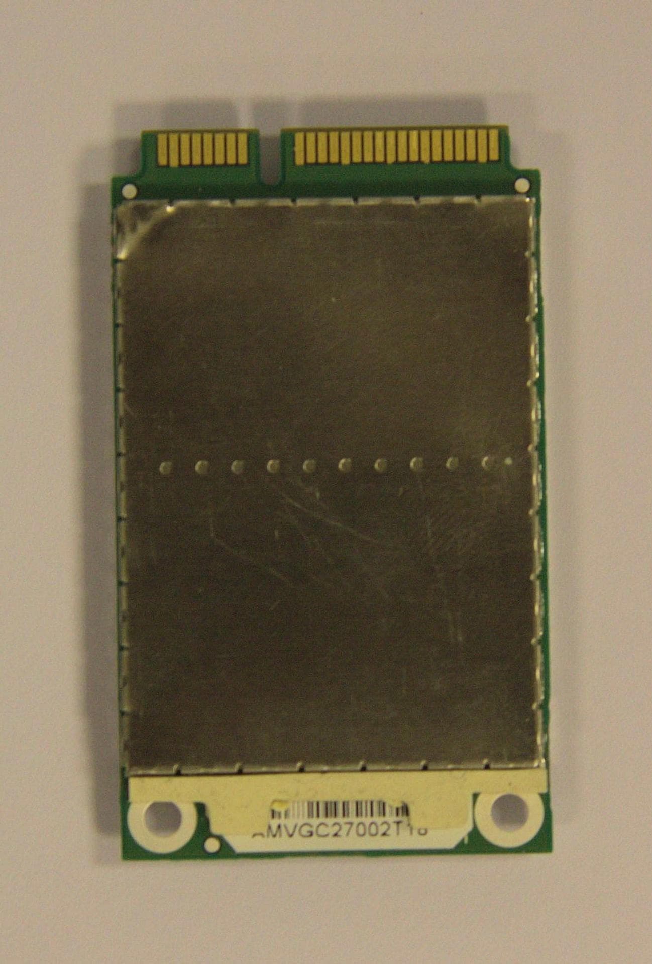
PKTPEMAMW1
Apr 03, 2014Broadband PCI Express Mini Module
Equipment Class
TNB - Licensed Non-Broadcast Station Transmitter
PKTUSBSTKARM
Dec 02, 2012LTE Band 12 USB Stick Modem
Equipment Class
TNB - Licensed Non-Broadcast Station Transmitter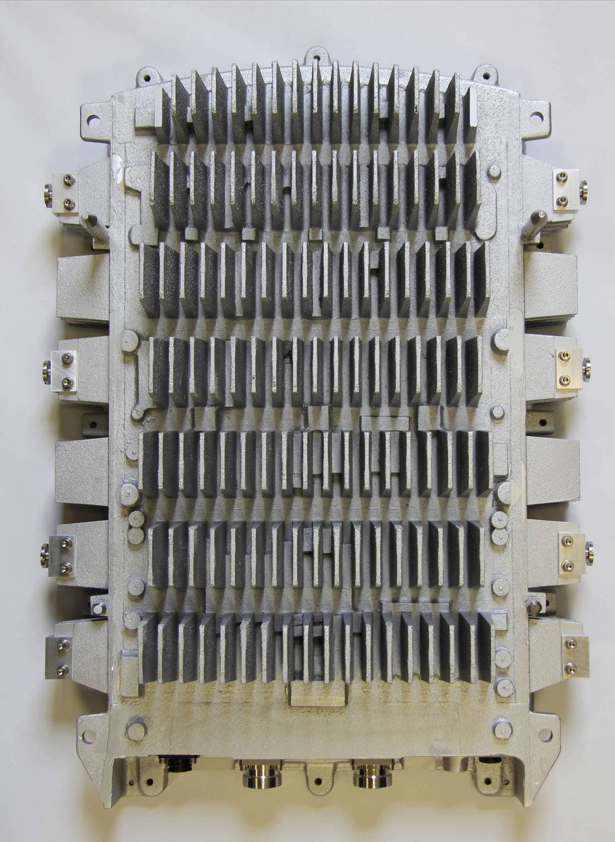
PKTNODEBAQQ
Oct 03, 20123GPP Band 12 LTE Base Station
Equipment Class
TNB - Licensed Non-Broadcast Station Transmitter