PKTPCMCIAFDWireless Broadband Modem
General Dynamics Broadband, Inc.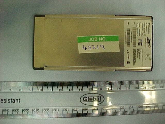
Click to zoom
Application Details
- Equipment Class
- TNB - Licensed Non-Broadcast Station Transmitter
- Date of Grant
- Aug 18, 2004
- Application Purpose
- Original Equipment
- Date of Application
- Aug 18, 2004
- Equipment Note
- Wireless Broadband Modem
- Frequency Range
- 2506.00000000 - 2680.00000000
- Country
- United States
Documents & Files
Document Text
Text extracted from the exhibit documents filed with the FCC. Open a document above to read the original.
Users Manual
Wireless Broadband Modem PCMCIA User Guide Version 0.2 W i r e l e s s B r o a d b a n d M o d e m U s e r G u i d e 2 Information in this document and the products described are subject to change without notice. Reproduction, alteration, or distribution in any manner whatsoever without the written permission of IPWireless Inc., is strictly forbidden. Trademarks used in this text: the IPWireless logo, icon, and Wireless Broadband Modem are trademarks of IPWireless, Inc.; Microsoft, Windows, and Windows NT are registered trademarks of Microsoft Corporation. Other trademarks and trade names may be used in this document to refer to either the entities claiming the marks and names or their products. IPWireless, Inc., disclaims any proprietary interest in trademarks and trade names other than its own. © 2000-2003 IPW ireless, Inc. All rights reserved. September 2003 Part No. IPW-0392 W i r e l e s s B r o a d b a n d M o d e m U s e r G u i d e 3 Table of Contents Introduction 5 Technical Support 5 Chapter 1 – Safety and Care Instructions 6 Safety Guidelines for Power Connection 6 Safety Guidelines for the Wireless Broadband Modem 6 Exposure to Radio Frequency Signals 7 Care and Cleaning Guidelines 7 Chapter 2 - Getting Started 9 Key Areas on Your Wireless Broadband Modem 9 Required Equipment 11 Package Contents 13 User Guide 13 Installation CD 13 Other Informational Material 13 Chapter 3 – Installation and Registration 14 How To Install the computer Client Software 14 How To Find the Best Radio Signal 16 How To Connect the Modem to the Computer 17 How To Perform Registration 18 Windows Operating System Patches 19 Windows Internet Configuration Setting 20 Chapter 4 – Connect to the Internet 21 Establishing the Connection to the Internet 23 W i r e l e s s B r o a d b a n d M o d e m U s e r G u i d e 4 Appendix A – Troubleshooting Tips 25 Troubleshooting Tips 25 Appendix C – Frequently Asked Questions 30 Appendix D – Modem Display Warnings 33 Power-On Self Test Failure 35 Software Upgrade Warning 35 Appendix E – [Technical Specifications] 36 Appendix H – Error Messages 38 Microsoft Remote Access Service (RAS) Error Codes 41 Wireless Broadband Modem Extended Errors 45 Regulatory Information 51 North America and Canada 51 Europe 52 Statements of Conformity 52 W i r e l e s s B r o a d b a n d M o d e m U s e r G u i d e 5 Introduction Congratulations on your selection of the Wireless Broadband Modem. Your Wireless Broadband Modem is designed to give you exceptional performance combined with easy installation and operation. Please read all safety and care instructions in Chapter 1 before installing your Wireless Broadband Modem for the first time. The Wireless Broadband Modem is a portable, wireless, cellular device that provides high-speed access to the Internet and offers high-bandwidth data downloads, uploads, and web browsing when connected to networks authorized for use with the Wireless Broadband Modem The design of the Wireless Broadband Modem is based on the standards of the latest third generation cellular communication technology, commonly known as 3G technology. The Wireless Broadband Modem doesn’t require an outdoor antenna, telephone jack, or additional home or office wiring. What's more, the Wireless Broadband Modem connects to the Internet through radio access -- you will never encounter dial-up busy signals or need to install an extra line to access the Internet and use the telephone at the same time. The speed at which your Wireless Broadband Modem will perform is dependent upon the radio signal quality available and the service level that you select. Information on how to determine and boost the signal quality is located in Chapter 3. Of course, your Wireless Broadband Modem can only connect to systems authorized for use with Wireless Broadband equipment. Service is not available in all areas; consult your Internet Service Provider (ISP) for details. Technical Support This User Guide provides you with step-by-step instructions on how to install and use your Wireless Broadband Modem. However, if you need further assistance, please contact your Service Provider for Technical Support. W i r e l e s s B r o a d b a n d M o d e m U s e r G u i d e 6 Chapter 1 – Safety and Care Instructions Before using your Wireless Broadband Modem for the first time, please read and follow all warnings, safety, care, cleaning and operating instructions on the Wireless Broadband Modem label and in this guide. These guidelines will help protect your Wireless Broadband Modem from potential damage and ensure your personal safety. Safety Guidelines for Power Connection Danger - Do not place or use the Wireless Broadband Modem near any body of water. Accidental immersion can result in electric shock. Safety Guidelines for the Wireless Broadband Modem Do not attempt to disassemble the Wireless Broadband Modem; doing so may expose you to unsafe conditions. The Wireless Broadband Modem does not contain consumer serviceable components. Service should be performed by the Service Provider Service Center only. Contact Service Provider Customer Service to find the nearest Service Center. Position the Wireless Broadband Modem so that it is protected from falling objects. Do not allow liquids to spill on or into the Wireless Broadband Modem. Do not expose the Wireless Broadband Modem to extreme hot (over 131° F/+55°C) or cold (under 14° F/-10°C) temperatures. Do not leave the Wireless Broadband Modem in a motor vehicle parked in direct sunlight for more than fifteen minutes. Do not expose the Wireless Broadband Modem to open flames. Do not alter the antenna or substitute any other antenna. Doing so may be unsafe. Switch your Wireless Broadband Modem off when near medical equipment, fuel, chemicals, a potentially explosive atmosphere such as a gasoline station, or when in an area in which blasting is in progress. Also, switch it off when on W i r e l e s s B r o a d b a n d M o d e m U s e r G u i d e 7 an aircraft…
Text truncated - open the document above for the full version.
External Photos
External Photographs Front Rear
ID Label/Location Info
PDFMAILER.COM Print and send PDF files as Emails with any application, ad-sponsored and free of charge www.pdfmailer.com FCC ID: PKTPCMCIAFD Complies with FCC Regulations Part 15. LISTED ACCESSORY 1AD3
Internal Photos
Internal Photographs Back Cover Removed Front Cover Removed Integral Antenna Internal Back View with Antenna Removed Internal Front View with Antenna Removed Internal Front View with Capacitor Removed Antenna PCB Back View Screens Removed PCB Front View Screens Removed
Parts List/Tune Up Info
This device is set at the factory, there is no tune-up procedure.
RF Exposure Info
RFI Global Services Ltd, Ewhurst Park, Ramsdell, Basingstoke, Hampshire, RG26 5RQ, ENGLAND. Tel: +44 (0) 1256 851193 Fax: +44 (0) 1256 851192 Registered in England, No. 211 7901. Registered Office: Pavilion A, Ashwood Park, Ashwood Way Basingstoke, Hampshire RG23 8BG TEST REPORT FROM RFI GLOBAL SERVICES LTD Test of: IPWireless. 2600 MHz PCMCIA Modem. (Body Measurements Only) To: OET Bulletin 65 Supplement C: (2001-01) Measurements were performed on the DASY4 System Test Report Serial No: RFI/SARE2/RP45219JD07A Supersedes Test Report Serial No: RFI/SARE1/RP45219JD07A This Test Report Is Issued Under The Authority Of Richard Jacklin, Operations Director: Checked By: Joe Lomako Tested By: Richelieu Quoi Release Version No: PDF001 Issue Date: 19 August 2004 Test Dates: 21 July 2004 to 28 July 2004 It should be noted that the standard, OET Bulletin 65 Supplement C: (2001-01) is not listed on RFI’s current UKAS schedule and is therefore “not UKAS accredited”. This report is issued in Adobe Acrobat portable document format (PDF). It is only a valid copy of the report if it is being viewed in PDF format with the following security options not allowed: Changing the document, Selecting text and graphics, Adding or changing notes and form fields. Furthermore, the date of creation must match the issue date stated above. This report may be copied in full. The results in this report apply only to the sample(s) tested. RFI GLOBAL SERVICES LTD. TEST REPORT S.No. RFI/SARE2/RP45219JD07A Page 2 of 62 Issue Date: 19 August 2004 Test Of: IPWireless. 2600 MHz PCMCIA Modem. To: OET Bulletin 65 Supplement C: (2001-01) This page has been left intentionally blank. RFI GLOBAL SERVICES LTD. TEST REPORT S.No. RFI/SARE2/RP45219JD07A Page 3 of 62 Issue Date: 19 August 2004 Test Of: IPWireless. 2600 MHz PCMCIA Modem. To: OET Bulletin 65 Supplement C: (2001-01) Table of Contents 1. Client Information ............................................................................................................. 4 2. Equipment Under Test (EUT) ........................................................................................... 5 3. Test Specification, Methods And Procedures................................................................ 9 4. Deviations From The Test Specification....................................................................... 10 5. Operation Of The EUT During Testing .......................................................................... 11 6. Summary Of Test Results .............................................................................................. 12 7. SAR Measurement System ............................................................................................ 23 8. SAR Safety Limits ...........................................................................................................24 9. Details of SAR Evaluation .............................................................................................. 25 10. Evaluation Procedures ................................................................................................. 26 11. System Validation ......................................................................................................... 27 12. Simulated Tissues ........................................................................................................ 28 13. Tissue Parameters ........................................................................................................ 29 14. DASY4 Systems Specifications................................................................................... 30 15. Validation results - 2450 MHz MSL Body .................................................................... 31 16. Validation results - 2450 MHz MSL Body .................................................................... 32 17. Validation results - 2450 MHz MSL Body .................................................................... 33 18. Validation results - 2450 MHz MSL Body .................................................................... 34 19. Measurement Uncertainty ............................................................................................ 35 Appendix 1. Test Equipment Used.................................................................................... 37 Appendix 2. SAR Distribution Scans ................................................................................ 38 Appendix 3. Test Configuration Photographs ................................................................. 41 Appendix 4. Calibration Data ............................................................................................. 43 Appendix 5 Photographs of EUT ....................................................................................... 45 Test Report Serial No: RFI/SARE2/RP45219JD07A Supersedes Test Report Serial No: RFI/SARE1/RP45219JD07A RFI GLOBAL SERVICES LTD. TEST REPORT S.No. RFI/SARE2/RP45219JD07A Page 4 of 62 Issue Date: 19 August 2004 Test Of: IPWireless. 2600 MHz PCMCIA Modem. To: OET Bulletin 65 Supplement C: (2001-01) 1. Client Information 1.1. Client Details Company Name: IPWireless UK Ltd. Address: 3-6 Charlton Business Park Crudwell Road Malmesbury Wiltshire SN16 9RU Contact Name: Mr P Warburg 1.2. Test Laboratory Company Name: Radio Frequency Investigation Ltd. Address: Ewhurst Park Ramsdell Basingstoke Hampshire RG26 5RQ. Contact Name: Mr J Lomako RFI GLOBAL SERVICES LTD. TEST REPORT S.No. RFI/SARE2/RP45219JD07A Page 5 of 62 Issue Date: 19 August 2004 Test Of: IPWireless. 2600 MHz PCMCIA Modem. To: OET Bulletin 65 Supplement C: (2001-01) 2. Equipment Under Test (EUT) The following information (with the exception of the Date of Receipt) has been supplied by the client: 2.1. Identification Of Equipment Under Test (EUT) Brand Name IPWireless Broadband Modem Model Name or Number FD Serial Number: FD5D34100F213 FCC ID Number PKTPCMCIAFD IMEI Number 351155000010070 Battery Serial Number Not Applicabl…
Text truncated - open the document above for the full version.
RF Exposure Info
RFI GLOBAL SERVICES LTD. TEST REPORT S.No. RFI/SARE2/RP45219JD07A Page 38 of 62 Issue Date: 19 August 2004 Test Of: IPWireless. 2600 MHz PCMCIA Modem. To: OET Bulletin 65 Supplement C: (2001-01) Appendix 2. SAR Distribution Scans This appendix contains SAR Distribution Scans. Plot Number Title GPH/45219/001 Flat Section 2600 MHz 12 MHz Channel 0 Degrees to Phantom PCMCIA Modem in Top Slot ACer Host GPH/45219/002 Flat Section 2600 MHz 12MHz Channel 0 Degrees to Phantom PCMCIA Modem in Bottom Slot ACer Host GPH/45219/003 Flat Section 2600 MHz 12 MHz Channel 90 Degrees to Phantom PCMCIA Modem in Bottom Slot ACer Host GPH/45219/004 Flat Section 2600 MHz 12 MHz Channel 90 Degrees to Phantom PCMCIA Modem in Bottom Slot ACer Host Worst Case Low GPH/45219/005 Flat Section2600 MHz 12 MHz Channel 90 Degrees to Phantom PCMCIA Modem in Bottom Slot ACer Host Worst Case High GPH/45219/006 Flat Section 2600 MHz 6 MHz Channel 0 Degrees to Phantom PCMCIA Modem in Top Slot ACer Host GPH/45219/007 Flat Section 2600 MHz 6 MHz Channel 0 Degrees to Phantom PCMCIA Modem in Bottom Slot ACer Host GPH/45219/008 Flat Section 2600 MHz 6 MHz Channel 90 Degrees to Phantom PCMCIA Modem in Bottom Slot ACer Host GPH/45219/009 Flat Section 2600 MHz 6 MHz Channel 90 Degrees to Phantom PCMCIA Modem in Bottom Slot ACer Host Worst Case Low GPH/45219/010 Flat Section 2600 MHz 6 MHz Channel 90 Degrees to Phantom PCMCIA Modem in Bottom Slot ACer Host Worst Case High GPH/45219/011 Flat Section 2600 MHz 12 MHz Channel 0 Degrees to Phantom PCMCIA Modem in Top Slot UMAX Host GPH/45219/012 Flat Section 2600 MHz 12 MHz Channel 0 Degrees to Phantom PCMCIA Modem in Bottom Slot UMAX Host GPH/45219/013 Flat Section 2600 MHz 12 MHz Channel 90 Degrees to Phantom PCMCIA Modem in Bottom Slot UMAX Host GPH/45219/014 Flat Section 2600 MHz 12 MHz Channel 90 Degrees to Phantom PCMCIA Modem in Bottom Slot UMAX Host Worst Case Low GPH/45219/015 Flat Section 2600 MHz 12 MHz Channel 90 Degrees to Phantom PCMCIA Modem in Bottom Slot UMAX Host Worst Case High GPH/45219/016 Flat Section 2600 MHz 6 MHz Channel 0 Degrees to Phantom PCMCIA Modem in Top Slot UMAX Host GPH/45219/017 Flat Section 2600 MHz 6 MHz Channel 0 Degrees to Phantom PCMCIA Modem in Bottom Slot UMAX Host GPH/45219/018 Flat Section 2600 MHz 6 MHz Channel 90 Degrees to Phantom PCMCIA Modem in Bottom Slot UMAX Host RFI GLOBAL SERVICES LTD. TEST REPORT S.No. RFI/SARE2/RP45219JD07A Page 39 of 62 Issue Date: 19 August 2004 Test Of: IPWireless. 2600 MHz PCMCIA Modem. To: OET Bulletin 65 Supplement C: (2001-01) SAR Distribution Scans (Continued) Plot Number Title GPH/45219/019 Flat Section 2600 MHz 6 MHz Channel 90 Degrees to Phantom PCMCIA Modem in Bottom Slot UMAX Host Worst Case Low GPH/45219/020 Flat Section 2600 MHz 6 MHz Channel 90 Degrees to Phantom PCMCIA Modem in Bottom Slot UMAX Host Worst Case High GPH/45219/021 Flat Section 2600 MHz 12 MHz Channel 0 Degrees to Phantom PCMCIA Modem in Slot Single Slot Only SONY Host GPH/45219/022 Flat Section 2600 MHz 12 MHz Channel 90 Degrees to Phantom PCMCIA Modem in Slot Single Slot Only SONY Host GPH/45219/023 Flat Section 2600 MHz 12 MHz Channel 90 Degrees to Phantom PCMCIA Modem in Slot Single Slot Only SONY Host Worst Case Low GPH/45219/024 Flat Section 2600 MHz 12 MHz Channel 90 Degrees to Phantom PCMCIA Modem in Slot Single Slot Only SONY Host Worst Case High GPH/45219/025 Flat Section 2600 MHz 6 MHz Channel 0 Degrees to Phantom PCMCIA Modem in Slot Single Slot Only SONY Host GPH/45219/026 Flat Section 2600 MHz 6 MHz Channel 90 Degrees to Phantom PCMCIA Modem in Slot Single Slot Only SONY Host GPH/45219/027 Flat Section 2600 MHz 6 MHz Channel 90 Degrees to Phantom PCMCIA Modem in Slot Single Slot Only SONY Host Worst Case Low GPH/45219/028 Flat Section 2600 MHz 6 MHz Channel 90 Degrees to Phantom PCMCIA Modem in Slot Single Slot Only SONY Host Worst Case High GPH/45219/029 Validation 001 GPH/45219/030 Validation 002 GPH/45219/031 Validation 003 GPH/45219/032 Validation 004 RFI GLOBAL SERVICES LTD. TEST REPORT S.No. RFI/SARE2/RP45219JD07A Page 40 of 62 Issue Date: 19 August 2004 Test Of: IPWireless. 2600 MHz PCMCIA Modem. To: OET Bulletin 65 Supplement C: (2001-01) This page has been left intentionally blank. Page 1 of 5 ...\45219_JD07_Flat_Section_2600MHz_12MHz Channel_ 0 Degrees to Phantom_PCMCIA_Modem21/07/2004 Date: 21/07/04 45219/07/001 Test Laboratory: RADIO FREQUENCY INVESTIGATION LTD. 45219_JD07_Flat_Section_2600MHz_12MHz Channel_ 0 Degrees to Phantom_PCMCIA_Modem_in_Top_Slot_ACer Host DUT: IP Wireless UK Ltd.; Type: 12MHz Channel PCMCIA Modem; Serial: FD5D34100F213 0 dB = 0.244mW/g Page 2 of 5 ...\45219_JD07_Flat_Section_2600MHz_12MHz Channel_ 0 Degrees to Phantom_PCMCIA_Mode 21/07/2004 Page 3 of 5 ...\45219_JD07_Flat_Section_2600MHz_12MHz Channel_ 0 Degrees to Phantom_PCMCIA_Mode 21/07/2004 Page 4 of 5 ...\45219_JD07_Flat_Section_2600MHz_12MHz Channel_ 0 Degrees to Phantom_PCMCIA_Mode 21/07/2004 Communication System: TDCDMA - 12MHz Channel; Frequency: 2596 MHz;Duty Cycle: 1:3 Medium: 2450MHz MSL Medium parameters used (interpolated): f = 2596 MHz; σ = 2.22 mho/m; ε r = Page 5 of 5 ...\45219_JD07_Flat_Section_2600MHz_12MHz Channel_ 0 Degrees to Phantom_PCMCIA_Mode 21/07/2004 53.1; ρ = 1000 kg/m 3 Phantom section: Flat Section DASY4 Configuration: - Probe: ET3DV6 - SN1529; ConvF(4.05, 4.05, 4.05); Calibrated: 09/06/2003 - Sensor-Surface: 4mm (Mechanical Surface Detection) - Electronics: DAE3 Sn394; Calibrated: 14/05/2004 - Phantom: SAM 12b; Type: SAM 4.0; Serial: TP:1197 - Measurement SW: DASY4, V4.2 Build 44; Postprocessing SW: SEMCAD, V1.8 Build 112 0 Degrees to Phantom, PCMCIA Modem in Top Slot/Area Scan (81x121x1): Measurement grid: dx=15mm, dy=15mm Reference Value = 7.36 V/m; Power Drift = -0.1 dB Maximum value of SAR (interpolated) = 0.305 mW/g 0 Degrees to Phantom, PCMCIA Modem in Top Slot/Zoom Scan (7x7x7)/Cube 0: Measurement grid: dx=5mm, dy=5mm, dz=5mm Reference Value = 7.36 V/m; Power Drift = -0.1 dB Maximum value of SAR …
Text truncated - open the document above for the full version.
RF Exposure Info
Page 1 of 3 ...\45219_JD07_Flat_Section_2600MHz_6MHz Channel_ 0 Degrees to Phantom_PCMCIA_Modem23/07/2004 Date: 23/07/04 45219/07/016 Test Laboratory: RADIO FREQUENCY INVESTIGATION LTD. 45219_JD07_Flat_Section_2600MHz_6MHz Channel_ 0 Degrees to Phantom_PCMCIA_Modem_in_Top_Slot_UMAX Host DUT: IP Wireless UK Ltd.; Type: 6MHz Channel PCMCIA Modem; Serial: FD5D34100F213 0 dB = 0.113mW/g Page 2 of 3 ...\45219_JD07_Flat_Section_2600MHz_6MHz Channel_ 0 Degrees to Phantom_PCMCIA_Mode 23/07/2004 Page 3 of 3 ...\45219_JD07_Flat_Section_2600MHz_6MHz Channel_ 0 Degrees to Phantom_PCMCIA_Mode 23/07/2004 Communication System: TDCDMA - 6MHz Channel; Frequency: 2596 MHz;Duty Cycle: 1:3 Medium: 2450MHz MSL Medium parameters used (interpolated): f = 2596 MHz; σ = 2.19 mho/m; ε r = 53.5; ρ = 1000 kg/m 3 Phantom section: Flat Section DASY4 Configuration: - Probe: ET3DV6 - SN1529; ConvF(4.05, 4.05, 4.05); Calibrated: 09/06/2003 - Sensor-Surface: 4mm (Mechanical Surface Detection) - Electronics: DAE3 Sn394; Calibrated: 14/05/2004 - Phantom: SAM 12b; Type: SAM 4.0; Serial: TP:1197 - Measurement SW: DASY4, V4.2 Build 44; Postprocessing SW: SEMCAD, V1.8 Build 112 0 Degrees to Phantom, PCMCIA Modem in Top Slot/Area Scan (81x121x1): Measurement grid: dx=15mm, dy=15mm Reference Value = 2.68 V/m; Power Drift = 0.1 dB Maximum value of SAR (interpolated) = 0.114 mW/g 0 Degrees to Phantom, PCMCIA Modem in Top Slot/Zoom Scan (7x7x7)/Cube 0: Measurement grid: dx=5mm, dy=5mm, dz=5mm Reference Value = 2.68 V/m; Power Drift = 0.1 dB Maximum value of SAR (measured) = 0.113 mW/g Peak SAR (extrapolated) = 0.238 W/kg SAR(1 g) = 0.108 mW/g; SAR(10 g) = 0.063 mW/g Page 1 of 3 ...\45219_JD07_Flat_Section_2600MHz_6MHz Channel_ 0 Degrees to Phantom_PCMCIA_Modem23/07/2004 Date: 23/07/04 45219/07/017 Test Laboratory: RADIO FREQUENCY INVESTIGATION LTD. 45219_JD07_Flat_Section_2600MHz_6MHz Channel_ 0 Degrees to Phantom_PCMCIA_Modem_in_Bottom_Slot_UMAX Host DUT: IP Wireless UK Ltd.; Type: 6MHz Channel PCMCIA Modem; Serial: FD5D34100F213 0 dB = 0.194mW/g Page 2 of 3 ...\45219_JD07_Flat_Section_2600MHz_6MHz Channel_ 0 Degrees to Phantom_PCMCIA_Mode 23/07/2004 Page 3 of 3 ...\45219_JD07_Flat_Section_2600MHz_6MHz Channel_ 0 Degrees to Phantom_PCMCIA_Mode 23/07/2004 Communication System: TDCDMA - 6MHz Channel; Frequency: 2596 MHz;Duty Cycle: 1:3 Medium: 2450MHz MSL Medium parameters used (interpolated): f = 2596 MHz; σ = 2.19 mho/m; ε r = 53.5; ρ = 1000 kg/m 3 Phantom section: Flat Section DASY4 Configuration: - Probe: ET3DV6 - SN1529; ConvF(4.05, 4.05, 4.05); Calibrated: 09/06/2003 - Sensor-Surface: 4mm (Mechanical Surface Detection) - Electronics: DAE3 Sn394; Calibrated: 14/05/2004 - Phantom: SAM 12b; Type: SAM 4.0; Serial: TP:1197 - Measurement SW: DASY4, V4.2 Build 44; Postprocessing SW: SEMCAD, V1.8 Build 112 0 Degrees to Phantom, PCMCIA Modem in Bottom Slot/Area Scan (81x121x1): Measurement grid: dx=15mm, dy=15mm Reference Value = 4.82 V/m; Power Drift = -7e-006 dB Maximum value of SAR (interpolated) = 0.200 mW/g 0 Degrees to Phantom, PCMCIA Modem in Bottom Slot/Zoom Scan (7x7x7)/Cube 0: Measurement grid: dx=5mm, dy=5mm, dz=5mm Reference Value = 4.82 V/m; Power Drift = -7e-006 dB Maximum value of SAR (measured) = 0.194 mW/g Peak SAR (extrapolated) = 0.379 W/kg SAR(1 g) = 0.184 mW/g; SAR(10 g) = 0.105 mW/g Page 1 of 3 ...\45219_JD07_Flat_Section_2600MHz_6MHz Channel_ 90 Degrees to Phantom_PCMCIA_Modem23/07/2004 Date: 23/07/04 45219/07/018 Test Laboratory: RADIO FREQUENCY INVESTIGATION LTD. 45219_JD07_Flat_Section_2600MHz_6MHz Channel_ 90 Degrees to Phantom_PCMCIA_Modem_in_Bottom_Slot_UMAX Host DUT: IP Wireless UK Ltd.; Type: 6MHz Channel PCMCIA Modem; Serial: FD5D34100F213 0 dB = 0.255mW/g Page 2 of 3 ...\45219_JD07_Flat_Section_2600MHz_6MHz Channel_ 90 Degrees to Phantom_PCMCIA_Mode 23/07/2004 Page 3 of 3 ...\45219_JD07_Flat_Section_2600MHz_6MHz Channel_ 90 Degrees to Phantom_PCMCIA_Mode 23/07/2004 Communication System: TDCDMA - 6MHz Channel; Frequency: 2596 MHz;Duty Cycle: 1:3 Medium: 2450MHz MSL Medium parameters used (interpolated): f = 2596 MHz; σ = 2.19 mho/m; ε r = 53.5; ρ = 1000 kg/m 3 Phantom section: Flat Section DASY4 Configuration: - Probe: ET3DV6 - SN1529; ConvF(4.05, 4.05, 4.05); Calibrated: 09/06/2003 - Sensor-Surface: 4mm (Mechanical Surface Detection) - Electronics: DAE3 Sn394; Calibrated: 14/05/2004 - Phantom: SAM 12b; Type: SAM 4.0; Serial: TP:1197 - Measurement SW: DASY4, V4.2 Build 44; Postprocessing SW: SEMCAD, V1.8 Build 112 90 Degrees to Phantom, PCMCIA Modem in Bottom Slot/Area Scan (61x51x1): Measurement grid: dx=15mm, dy=15mm Reference Value = 9.52 V/m; Power Drift = -0.2 dB Maximum value of SAR (interpolated) = 0.262 mW/g 90 Degrees to Phantom, PCMCIA Modem in Bottom Slot/Zoom Scan (7x7x7)/Cube 0: Measurement grid: dx=5mm, dy=5mm, dz=5mm Reference Value = 9.52 V/m; Power Drift = -0.2 dB Maximum value of SAR (measured) = 0.255 mW/g Peak SAR (extrapolated) = 0.557 W/kg SAR(1 g) = 0.246 mW/g; SAR(10 g) = 0.136 mW/g Page 1 of 3 ...\45219_JD07_Flat_Section_2600MHz_6MHz Channel_ 90 Degrees to Phantom_PCMCIA_Modem23/07/2004 Date: 23/07/04 45219/07/019 Test Laboratory: RADIO FREQUENCY INVESTIGATION LTD. 45219_JD07_Flat_Section_2600MHz_6MHz Channel_ 90 Degrees to Phantom_PCMCIA_Modem_in_Bottom_Slot_UMAX Host_Worst_Case_Low DUT: IP Wireless UK Ltd.; Type: 6MHz Channel PCMCIA Modem; Serial: FD5D34100F213 0 dB = 0.210mW/g Page 2 of 3 ...\45219_JD07_Flat_Section_2600MHz_6MHz Channel_ 90 Degrees to Phantom_PCMCIA_Mode 23/07/2004 Page 3 of 3 ...\45219_JD07_Flat_Section_2600MHz_6MHz Channel_ 90 Degrees to Phantom_PCMCIA_Mode 23/07/2004 Communication System: TDCDMA - 6MHz Channel; Frequency: 2503 MHz;Duty Cycle: 1:3 Medium: 2450MHz MSL Medium parameters used (interpolated): f = 2503 MHz; σ = 2.06 mho/m; ε r = 53.9; ρ = 1000 kg/m 3 Phantom section: Flat Section DASY4 Configuration: - Probe: ET3DV6 - SN1529; ConvF(4.05, 4.05, 4.05); Calibrated: 09/06/2003 - Sensor-Surface: 4mm (Mechanical Surface Detection) - Electronics: DAE3 S…
Text truncated - open the document above for the full version.
RF Exposure Info
RFI GLOBAL SERVICES LTD. TEST REPORT S.No. RFI/SARE2/RP45219JD07A Page 41 of 62 Issue Date: 19 August 2004 Test Of: IPWireless. 2600 MHz PCMCIA Modem. To: OET Bulletin 65 Supplement C: (2001-01) Appendix 3. Test Configuration Photographs This appendix contains photographs showing the test configuration for the measurement of Specific Absorption Rate (SAR) RFI GLOBAL SERVICES LTD. TEST REPORT S.No. RFI/SARE2/RP45219JD07A Page 42 of 62 Issue Date: 19 August 2004 Test Of: IPWireless. 2600 MHz PCMCIA Modem. To: OET Bulletin 65 Supplement C: (2001-01) Test Configuration Photographs (Continued) RFI GLOBAL SERVICES LTD. TEST REPORT S.No. RFI/SARE2/RP45219JD07A Page 43 of 62 Issue Date: 19 August 2004 Test Of: IPWireless. 2600 MHz PCMCIA Modem. To: OET Bulletin 65 Supplement C: (2001-01) Appendix 4. Calibration Data This appendix contains the calibration data and certificates. RFI GLOBAL SERVICES LTD. TEST REPORT S.No. RFI/SARE2/RP45219JD07A Page 44 of 62 Issue Date: 19 August 2004 Test Of: IPWireless. 2600 MHz PCMCIA Modem. To: OET Bulletin 65 Supplement C: (2001-01) This page has been left intentionally blank RFI GLOBAL SERVICES LTD. TEST REPORT S.No. RFI/SARE2/RP45219JD07A Page 45 of 62 Issue Date: 19 August 2004 Test Of: IPWireless. 2600 MHz PCMCIA Modem. To: OET Bulletin 65 Supplement C: (2001-01) Appendix 5 Photographs of EUT This appendix contains the following photographs: Photo Reference Number Title PHT/45219/001 2450 MHz MSL Fluid Level PHT/45219/002 ACer Host Laptop with PCMCIA Modem in Bottom Slot, 0 Degrees to Phantom PHT/45219/003 ACer Host Laptop with PCMIA Modem in Top Slot, 0 Degrees to Phantom PHT/45219/004 ACer Host Laptop with PCMCIA Modem, 90 Degrees to Phantom PHT/45219/005 Close-up View of ACer Host Laptop with PCMCIA Modem in Top Slot, 0 Degrees to Phantom PHT/45219/006 Close-up View of ACer Host Laptop with PCMCIA Modem in Top Slot, 0 Degrees to Phantom PHT/45219/007 Close-up View of PCMCIA Modem PHT/45219/008 Close-up View of Sony Host Laptop with PCMCIA Modem, 0 Degrees to Phantom PHT/45219/009 Close-up View of UMAX Host Laptop with PCMCIA Modem in Top Slot, 0 Degrees to Phantom PHT/45219/010 Close-up View of UMAX Host Laptop with PCMCIA Modem in Top Slot, 0 Degrees to Phantom PHT/45219/011 PCMCIA Modem View 1 PHT/45219/012 PCMCIA Modem View 2 PHT/45219/013 Sony Host Laptop with PCMCIA Modem, 0 Degrees to Phantom PHT/45219/014 Sony Host Laptop with PCMCIA Modem, 90 Degrees to Phantom PHT/45219/015 UMAX Host Laptop with PCMCIA Modem in Bottom Slot, 0 Degrees to Phantom PHT/45219/016 UMAX Host Laptop with PCMCIA Modem in Top Slot, 0 Degrees to Phantom PHT/45219/017 UMAX Host Laptop with PCMCIA Modem, 90 Degrees to Phantom RFI GLOBAL SERVICES LTD. TEST REPORT S.No. RFI/SARE2/RP45219JD07A Page 46 of 62 Issue Date: 19 August 2004 Test Of: IPWireless. 2600 MHz PCMCIA Modem. To: OET Bulletin 65 Supplement C: (2001-01) PHT/45219/001 2450 MHz MSL Fluid Level RFI GLOBAL SERVICES LTD. TEST REPORT S.No. RFI/SARE2/RP45219JD07A Page 47 of 62 Issue Date: 19 August 2004 Test Of: IPWireless. 2600 MHz PCMCIA Modem. To: OET Bulletin 65 Supplement C: (2001-01) PHT/45219/002 ACer Host Laptop with PCMCIA Modem in Bottom Slot, 0 Degrees to Phantom RFI GLOBAL SERVICES LTD. TEST REPORT S.No. RFI/SARE2/RP45219JD07A Page 48 of 62 Issue Date: 19 August 2004 Test Of: IPWireless. 2600 MHz PCMCIA Modem. To: OET Bulletin 65 Supplement C: (2001-01) PHT/45219/003 ACer Host Laptop with PCMIA Modem in Top Slot, 0 Degrees to Phantom RFI GLOBAL SERVICES LTD. TEST REPORT S.No. RFI/SARE2/RP45219JD07A Page 49 of 62 Issue Date: 19 August 2004 Test Of: IPWireless. 2600 MHz PCMCIA Modem. To: OET Bulletin 65 Supplement C: (2001-01) PHT/45219/004 ACer Host Laptop with PCMCIA Modem, 90 Degrees to Phantom RFI GLOBAL SERVICES LTD. TEST REPORT S.No. RFI/SARE2/RP45219JD07A Page 50 of 62 Issue Date: 19 August 2004 Test Of: IPWireless. 2600 MHz PCMCIA Modem. To: OET Bulletin 65 Supplement C: (2001-01) PHT/45219/005 Close-up View of ACer Host Laptop with PCMCIA Modem in Top Slot, 0 Degrees to Phantom RFI GLOBAL SERVICES LTD. TEST REPORT S.No. RFI/SARE2/RP45219JD07A Page 51 of 62 Issue Date: 19 August 2004 Test Of: IPWireless. 2600 MHz PCMCIA Modem. To: OET Bulletin 65 Supplement C: (2001-01) PHT/45219/006 Close-up View of ACer Host Laptop with PCMCIA Modem in Top Slot, 0 Degrees to Phantom RFI GLOBAL SERVICES LTD. TEST REPORT S.No. RFI/SARE2/RP45219JD07A Page 52 of 62 Issue Date: 19 August 2004 Test Of: IPWireless. 2600 MHz PCMCIA Modem. To: OET Bulletin 65 Supplement C: (2001-01) PHT/45219/007 Close-up View of PCMCIA Modem RFI GLOBAL SERVICES LTD. TEST REPORT S.No. RFI/SARE2/RP45219JD07A Page 53 of 62 Issue Date: 19 August 2004 Test Of: IPWireless. 2600 MHz PCMCIA Modem. To: OET Bulletin 65 Supplement C: (2001-01) PHT/45219/008 Close-up View of SONY Host Laptop with PCMCIA Modem, 0 Degrees to Phantom RFI GLOBAL SERVICES LTD. TEST REPORT S.No. RFI/SARE2/RP45219JD07A Page 54 of 62 Issue Date: 19 August 2004 Test Of: IPWireless. 2600 MHz PCMCIA Modem. To: OET Bulletin 65 Supplement C: (2001-01) PHT/45219/009 Close-up View of UMAX Host Laptop with PCMCIA Modem in Top Slot, 0 Degrees to Phantom RFI GLOBAL SERVICES LTD. TEST REPORT S.No. RFI/SARE2/RP45219JD07A Page 55 of 62 Issue Date: 19 August 2004 Test Of: IPWireless. 2600 MHz PCMCIA Modem. To: OET Bulletin 65 Supplement C: (2001-01) PHT/45219/010 Close-up View of UMAX Host Laptop with PCMCIA Modem in Top Slot, 0 Degr…
Text truncated - open the document above for the full version.
Contact Information
Applicant
Joseph Cheung
Technical Contact
IPWireless (UK) LtdPeter Warburg
[email protected]+44 1666 828 700
Units 3-6 Charlton Business Park · Malmesbury, Wiltshire · United Kingdom
Test Firm
RFI Global Services Ltd.Allan Hume
Technical Specifications
| # | Rule Parts | Frequency Range | Power Output | Emission | Tolerance |
|---|---|---|---|---|---|
| 4 | 74 | 2.51 GHz - 2.68 GHz | 230.00 mW | 8M36G7D | 0.01 ppm |
Other Applications from General Dynamics Broadband, Inc.
PKTNODEBAZY
Oct 21, 2015Band 12 LTE Base Station
Equipment Class
TNB - Licensed Non-Broadcast Station Transmitter
PKTNODEBBBK
Mar 23, 2015Band 14 LTE Base Station
Equipment Class
TNB - Licensed Non-Broadcast Station Transmitter
PKTPEMAMW1
Apr 03, 2014Broadband PCI Express Mini Module
Equipment Class
TNB - Licensed Non-Broadcast Station Transmitter
PKTUSBSTKARM
Dec 02, 2012LTE Band 12 USB Stick Modem
Equipment Class
TNB - Licensed Non-Broadcast Station Transmitter
PKTNODEBAQQ
Oct 03, 20123GPP Band 12 LTE Base Station
Equipment Class
TNB - Licensed Non-Broadcast Station Transmitter