PKTUSBSTKADTUSB Modem
General Dynamics Broadband, Inc.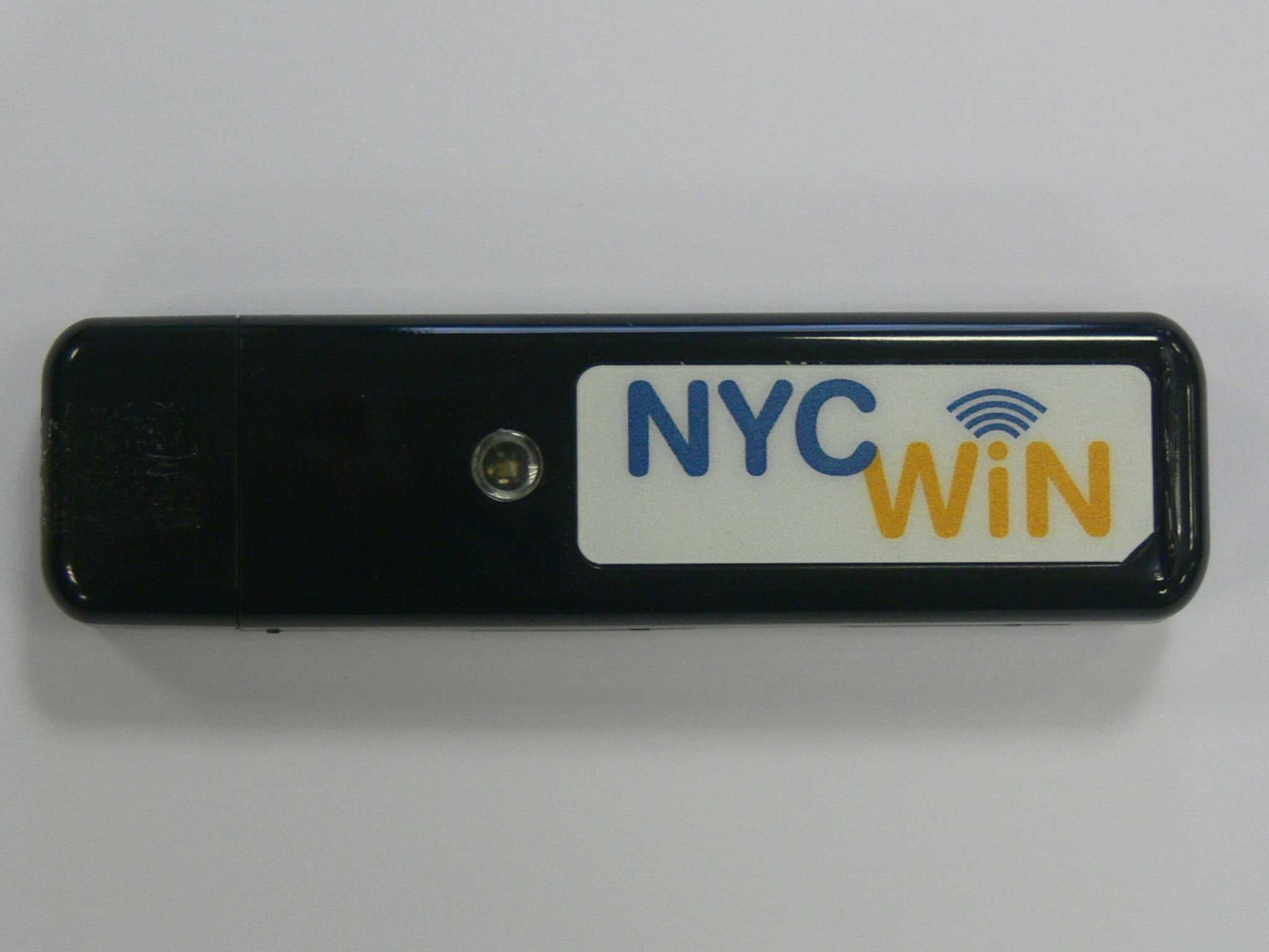
Click to zoom
Application Details
- Equipment Class
- TNB - Licensed Non-Broadcast Station Transmitter
- Date of Grant
- Jan 21, 2010
- Application Purpose
- Original Equipment
- Date of Application
- Jan 07, 2010
- Equipment Note
- USB Modem
- Frequency Range
- 2496.00000000 - 2690.00000000
- Country
- United States
Documents & Files
Document Text
Text extracted from the exhibit documents filed with the FCC. Open a document above to read the original.
Users Manual
Wireless Broadband Modem USB-Stick-Modem Quick Start Guide Important Notes: Run the installation CD-ROM provided before connecting the USB Stick Modem to the computer. The installation software will instruct the user when to insert the USB-Modem into the computer If you wish to disconnect the USB Stick Modem from the computer card it is important to first make it safe for removal. Do this by clicking on the icon in the toolbar on the lower right of the screen and selecting STOP. Caution: This USB modem is approved for use in normal size laptop computers only (typically with 12 inch or larger display screens). To comply with FCC RF exposure requirements, this modem should not be used in configurations that cannot maintain a distance of at least 5mm (approximately 0.2 inch) from users and bystanders. Antennas (internal) Status Indicator SIM Card Tray (beneath USB Connector - if fitted) USB Connector (Cap removed) - 2 - Getting Started This Quick Start Guide gives basic installation and configuration instructions. Follow the instructions on the following pages to install the USB Stick Modem client software and driver files, before connecting the modem to the computer and then perform on-line registration. Refer to the User Guide on the installation CD-ROM for the complete installation, upgrade and configuration procedures. Be sure to complete each of the following steps outlined below before moving on to the next step. SIM Card (if required) You have been supplied with a username and password to be used when connecting to the TDD network. The SIM may not always be required when authenticating TDD networks, check with your service provider. The SIM card is inserted directly into the modem below the USB connector, there is no SIM tray. Before removing the SIM card from the Modem, it is good practice and recommended that a safe hardware removal procedure is always followed for the Modem device. Disconnect and close the Client Software application. To remove the USB Stick Modem first locate the “Safely Remove Hardware” Icon shown above from the notification area usually to the right of the task bar. Using the mouse, left click on the icon. A “Safely remove ...” notification will be displayed similar to the one below. Click on the IPWireless Network Adapter to safely power off the adapter. Note: If the adapter is in use i.e. connected to a network or the Client Software is open and displaying status, you will see a notification informing you that it is not possible to remove the adapter. Ensure that the Client Software is disconnected and closed before a safe removal. To connect to the TDD network you must first enter your username and password details in the Client Software using the Change User Details button near the bottom of the Application. When connected the Client Software will minimize to the notification bar next to the clock. The application can be restored by double clicking on this icon shown below. - 3 - Step 1. Install Client Software and USB Stick Modem Drivers Follow the instructions according to your installed operating system. Windows 2000™ You must log in with administrative privileges 1. Close any programs that may be running and insert the CD into the CD-ROM drive on your computer. If the CD does not autorun and display a start screen, select Start->Run and enter d:\Setup.exe where d is your CD-ROM drive letter. 2. The Installation Setup Wizard will then prompt you through each step of the installation. (Use the Next> and <Back buttons to navigate the wizard and click Finish on the final screen). 3. When you reach the Licence Agreement screen, the installation will not proceed further unless you accept the terms of the License Agreement. 4. The installation software will then copy the Client Software and USB Stick Modem driver files onto your computer from the installation CD. 5. When the transfer of files to the computer is complete, you will be asked to to plug the USB Stick Modem + provided USB cable into your computer. Windows Vista™, Windows XP™ You must log in with administrative privileges 1. Close any programs that may be running and insert the CD into the CD-ROM drive on your computer. If the CD does not autorun and display a start screen, select Start->Run and enter d:\Setup.exe where d is your CD-ROM drive letter. 2. The Installation Setup Wizard will then prompt you through each step of the installation. (Use the Next> and <Back buttons to navigate the wizard and click Finish on the final screen). 3. When you reach the Licence Agreement screen, the installation will not proceed further unless you accept the terms of the License Agreement. 4. The installation software will then copy the Client Software and USB Stick Modem driver files onto your computer from the installation CD. 5. When the transfer of files to the computer is complete, you will be asked to plug the USB Stick Modem into your computer. - 4 - Step 2. Insert the USB Stick Modem and Obtain the Best Radio Signal Fit the SIM or USIM card, where one has been provided, into the SIM slot in the USB Stick Modem, observing the correct orientation and with the gold contacts on the SIM/USIM face down. Connnect the USB Stick Modem into a USB port on your computer either directly or using the cable supplied. The modem will draw power from the computer that it needs in order to operate. The red power on indicator will glow steady after a few seconds to indicate that it is ready for operation. To obtain the best signal strength position the USB Stick Modem near a window. If connection fails with low signal strength try relocating the USB Stick Modem. When the computer detects that the USB Stick Modem has been connected,, the computer will attempt to use the USB Stick Modem driver files that were loaded during step 1. The USB Stick Modem will automatically attempt to find a base station. During this process the green connection indicator will flash on and off, when connection is established the indicator will beco…
Text truncated - open the document above for the full version.
Users Manual
Wireless Broadband Modem USB-Stick December 2009 Part No. IPW-2114_issue1 Antennae (internal) Status Indicator USB Connector (under removable cap) Important Notes: Run the installation CD-ROM provided before connecting the USB Stick Modem to the computer. The installation software will instruct when to connect the USB Stick Modem to the computer. If you wish to disconnect the USB Stick Modem from the computer it is important to first make it safe for removal. Do this by clicking on the icon in the toolbar on the lower right of the screen and selecting STOP. Caution: This USB modem is approved for use in normal size laptop computers only (typically with 12 inch or larger display screens). To comply with FCC RF exposure requirements, this modem should not be used in configurations that cannot maintain at least 5 mm (approximately 0.2 inch) from users and bystanders. The user is advised to refer to the instruction manual for further clarification and explanation on how to maintain RF exposure compliance.
Cover Letter(s)
RFI Global Services Ltd Pavilion A, Ashwood Park, Ashwood Way, Basingstoke, Hampshire, RG23 8BG Tel: +44 (0) 1256 312000 Fax: +44 (0) 1256 312001 Email: [email protected] Website: www.rfi-global.com Registered in England and Wales Company number: 2117901 Confirmation of equipment Set Up for SAR Testing - PKTUSBSTKADT The EUT was tested in the following operating mode(s): • TDCDMA Data allocated mode using test harness Software with 6 Uplink and 9 Downlink and duty cycle of 40%. • Commercial test equipment is not available to support TD-CDMA user devices. The USB Stick modem is compliant at the physical layer but not 100% compliant in the MAC layer due to additional enhancements to optimise the use of shared channels. Therefore to support the required testing, a support application known as “test harness” was used to configure the device into representative operating configurations. This is an open ended configuration that does not require the device to communicate with a network or simulator. This software allows the device to be controlled over the USB interface and the software allows access and control over the internal operation of the modem. The test harness software does not setup up a loopback and is completely stand-alone in operation; the software uses pre-configured test scripts to configure the device under test into the required test configurations. • All modulation types (QPSK, 16QAM and 64QAM) were evaluated on both Low and High chip rate. • All orientations (Horizontal-Down, Horizontal-Up, Vertical-Front, Vertical-Back and Top or Tip) were evaluated in the low, middle and high channels for Low chip rate (CH: 12494, CH: 12965 & CH 13436) and High chip rate (CH: 12507, CH: 12965 & CH: 13420). The ‘top or tip’ of the dongle was evaluated as the antenna is located at the upper section of the dongle. • All measurements were performed at 5mm separation from the ‘SAM’ phantom flat section. • Below are the configuration covered as per KDB 47498 D02 SAR Procedures for Dongle Xmtr v02. Appendix 4 shows the EUT setup in these configurations. RFI Global Services Ltd
RF Exposure Info
TEST REPORT FROM RFI GLOBAL SERVICES LTD Test of: ADT USB Dongle To: OET Bulletin 65 Supplement C: (2001-01) Test Report Serial No: RFI/SAR2/RP76288JD01A Supersedes Test Report Serial No: RFI/SAR1/RP76288JD01A This Test Report Is Issued Under The Authority Of Scott D’Adamo, Group Service Manager Global Approvals: Checked By: Scott D'Adamo Report Copy No: PDF01 Issue Date: 19 January 2010 Test Dates: 03 December 2009 to 15 January 2010 This report is issued in Adobe Acrobat portable document format (PDF). It is only a valid copy of the report if it is being viewed in PDF format with the following security options not allowed: Changing the document, Selecting text and graphics, Adding or changing notes and form fields. This report may be copied in full. The results in this report apply only to the sample(s) tested. RFI GLOBAL SERVICES LTD Test Report Serial No: RFI/SAR2/RP76288JD01A Page: 2 of 169 Issue Date: 19 January 2010 Test of: ADT USB Dongle To: OET Bulletin 65 Supplement C: (2001-01) This page has been left intentionally blank. RFI GLOBAL SERVICES LTD Test Report Serial No: RFI/SAR2/RP76288JD01A Page: 3 of 169 Issue Date: 19 January 2010 Test of: ADT USB Dongle To: OET Bulletin 65 Supplement C: (2001-01) Table of Contents 1. Customer Information ...................................................................................................... 4 2. Equipment Under Test (EUT) ........................................................................................... 5 3. Test Specification, Methods and Procedures ................................................................ 8 4. Deviations from the Test Specification .......................................................................... 9 5. Operation and Configuration of the EUT during Testing ............................................ 10 6. Summary of Test Results............................................................................................... 12 7. Measurements, Examinations and Derived Results.................................................... 13 8. Measurement Uncertainty.............................................................................................. 22 Appendix 1. Test Equipment Used.................................................................................... 24 Appendix 2. Measurement Methods ................................................................................. 27 Appendix 3. SAR Distribution Scans ................................................................................ 29 Appendix 4. Photographs ................................................................................................ 137 Appendix 5. Validation of System ................................................................................... 156 Appendix 6. Simulated Tissues....................................................................................... 166 Appendix 7. DASY4 System Details ................................................................................ 167 RFI GLOBAL SERVICES LTD Test Report Serial No: RFI/SAR2/RP76288JD01A Page: 4 of 169 Issue Date: 19 January 2010 Test of: ADT USB Dongle To: OET Bulletin 65 Supplement C: (2001-01) 1. Customer Information Company Name: IP Wireless (UK) Ltd. Address: Unit 7 Greenways Business Park Bellinger Close Chippenham Wiltshire SN15 1BN RFI GLOBAL SERVICES LTD Test Report Serial No: RFI/SAR2/RP76288JD01A Page: 5 of 169 Issue Date: 19 January 2010 Test of: ADT USB Dongle To: OET Bulletin 65 Supplement C: (2001-01) 2. Equipment Under Test (EUT) The following information (with the exception of the date of receipt) has been supplied by the customer: 2.1. Identification of Equipment Under Test (EUT) Description: USB Dongle Brand Name: IP Wireless (UK) Ltd. Model Name or Number: ADT Serial Number: ADWA928000816 (PCB Serial Number) IMEI Number: Not Applicable Hardware Version Number: Version 1 Software Version Number: 5.6.3 Hardware Revision of GSM Module: Not Applicable Software Revision of GSM Module: Not Applicable FCC ID Number: PKTUSBSTKADT Country of Manufacture: None Stated Date of Receipt: 03 November 2009 2.2. Description of EUT The Equipment Under Test is a USB Dongle Stick Modem with TDCDMA 2.5GHz band support. 2.3. Modifications Incorporated in the EUT There were no modifications incorporated in the EUT. 2.4. Accessories The following accessories were supplied with the EUT during testing: Description: USB Cable Brand Name: None Stated on cable Model Name or Number: None Stated on cable Serial Number: Not Applicable Cable Length and Type: ~132.5mm USB Cable Country of Manufacture: None Sated Connected to Port USB Port on Laptop to USB Connection on Dongle RFI GLOBAL SERVICES LTD Test Report Serial No: RFI/SAR2/RP76288JD01A Page: 6 of 169 Issue Date: 19 January 2010 Test of: ADT USB Dongle To: OET Bulletin 65 Supplement C: (2001-01) Support Equipment The following support equipment was used to exercise the EUT during testing: Description: Laptop PC with Horizontal USB port Brand Name: Toshiba Model Name or Number: PSAAPE-00H00KEN Serial Number: 67 0709710 Cable Length and Type: Not Applicable Connected to Port: USB Description: Laptop PC with Vertical USB port Brand Name: Dell Model Name or Number: Latitude D620 Serial Number: None Stated Cable Length and Type: Not Applicable Connected to Port: USB RFI GLOBAL SERVICES LTD Test Report Serial No: RFI/SAR2/RP76288JD01A Page: 7 of 169 Issue Date: 19 January 2010 Test of: ADT USB Dongle To: OET Bulletin 65 Supplement C: (2001-01) 2.5. Additional Information Related to Testing Equipment Category 2.5 GHz TDCDMA Type of Unit Portable Transceiver Intended Operating Environment: Within the TDCDMA Emergency Services Coverage Low Chip Rate: 2.5GHz TDCDMA 24 dBm Transmitter Maximum Output Power Characteristics: High Chip Rate: 2.5GHz TDCDMA 24 dBm Low Chip Rate: 2.5GHz TDCDMA (2498 to 2688 ) MHz Transmitter Frequency Range: High Chip Rate: 2.5GHz TDCDMA (2501 to 2685 ) MHz Channel Number…
Text truncated - open the document above for the full version.
RF Exposure Info
RFI GLOBAL SERVICES LTD Test Report Serial No: RFI/SAR2/RP76288JD01A Page: 82 of 169 Issue Date: 19 January 2010 Test of: ADT USB Dongle To: OET Bulletin 65 Supplement C: (2001-01) Date 07/11/2009 SCN/76288JD01/049 - Vertical-Front of EUT Facing Phantom TD-CDMA 7.68 Mcps 64QAM CH12507 6 Time Slots DUT: IPWireless; Type: ADT; Serial: ADWA928000816 0 dB = 1.07mW/g Communication System: TDCDMA - 7.68 Mcps / 10MHz Channel; Frequency: 2501.4 MHz;Duty Cycle: 1:2.5 Medium: 2450 MHz MSL Medium parameters used (interpolated): f = 2501.4 MHz; σ = 1.94 mho/m; ε r = 50.6; ρ = 1000 kg/m 3 Phantom section: Flat Section DASY4 Configuration: - Probe: EX3DV3 - SN3508; ConvF(8.06, 8.06, 8.06); Calibrated: 26/06/2009 - Sensor-Surface: 4mm (Mechanical Surface Detection) - Electronics: DAE3 Sn450; Calibrated: 30/04/2009 - Phantom: SAM 12a; Type: SAM 4.0; Serial: TP:1193 - Measurement SW: DASY4, V4.7 Build 55; Postprocessing SW: SEMCAD, V1.8 Build 176 Vertical Front of EUT Facing Phantom - Low/Area Scan (71x111x1): Measurement grid: dx=15mm, dy=15mm Maximum value of SAR (interpolated) = 1.01 mW/g Vertical Front of EUT Facing Phantom - Low/Zoom Scan (7x7x7) (7x7x7)/Cube 0: Measurement grid: dx=5mm, dy=5mm, dz=5mm Reference Value = 8.51 V/m; Power Drift = 0.036 dB Peak SAR (extrapolated) = 1.95 W/kg SAR(1 g) = 0.954 mW/g; SAR(10 g) = 0.440 mW/g Maximum value of SAR (measured) = 1.07 mW/g RFI GLOBAL SERVICES LTD Test Report Serial No: RFI/SAR2/RP76288JD01A Page: 83 of 169 Issue Date: 19 January 2010 Test of: ADT USB Dongle To: OET Bulletin 65 Supplement C: (2001-01) Date 08/11/2009 SCN/76288JD01/050 - Vertical-Front of EUT Facing Phantom TD-CDMA 7.68 Mcps 64QAM CH12965 6 Time Slots DUT: IPWireless; Type: ADT; Serial: ADWA928000816 0 dB = 1.02mW/g Communication System: TDCDMA - 7.68 Mcps / 10MHz Channel; Frequency: 2593 MHz;Duty Cycle: 1:2.5 Medium: 2450 MHz MSL Medium parameters used (interpolated): f = 2593 MHz; σ = 2.07 mho/m; ε r = 50.5; ρ = 1000 kg/m 3 Phantom section: Flat Section DASY4 Configuration: - Probe: EX3DV3 - SN3508add; ConvF(7.73, 7.73, 7.73); Calibrated: 16/01/2009 - Sensor-Surface: 4mm (Mechanical Surface Detection) - Electronics: DAE3 Sn450; Calibrated: 30/04/2009 - Phantom: SAM 12a; Type: SAM 4.0; Serial: TP:1193 - Measurement SW: DASY4, V4.7 Build 55; Postprocessing SW: SEMCAD, V1.8 Build 176 Vertical Front of EUT Facing Phantom - Middle/Area Scan (71x111x1): Measurement grid: dx=15mm, dy=15mm Maximum value of SAR (interpolated) = 0.930 mW/g Vertical Front of EUT Facing Phantom - Middle/Zoom Scan (7x7x7) (7x7x7)/Cube 0: Measurement grid: dx=5mm, dy=5mm, dz=5mm Reference Value = 20.7 V/m; Power Drift = -0.041 dB Peak SAR (extrapolated) = 1.79 W/kg SAR(1 g) = 0.900 mW/g; SAR(10 g) = 0.418 mW/g Maximum value of SAR (measured) = 1.02 mW/g RFI GLOBAL SERVICES LTD Test Report Serial No: RFI/SAR2/RP76288JD01A Page: 84 of 169 Issue Date: 19 January 2010 Test of: ADT USB Dongle To: OET Bulletin 65 Supplement C: (2001-01) Date 08/11/2009 SCN/76288JD01/051 - Vertical-Front of EUT Facing Phantom TD-CDMA 7.68 Mcps 64QAM CH13420 6 Time Slots DUT: IPWireless; Type: ADT; Serial: ADWA928000816 0 dB = 0.516mW/g Communication System: TDCDMA - 7.68 Mcps / 10MHz Channel; Frequency: 2684.6 MHz;Duty Cycle: 1:2.5 Medium: 2450 MHz MSL Medium parameters used (interpolated): f = 2684.6 MHz; σ = 2.19 mho/m; ε r = 50.2; ρ = 1000 kg/m 3 Phantom section: Flat Section DASY4 Configuration: - Probe: EX3DV3 - SN3508add; ConvF(7.73, 7.73, 7.73); Calibrated: 16/01/2009 - Sensor-Surface: 4mm (Mechanical Surface Detection) - Electronics: DAE3 Sn450; Calibrated: 30/04/2009 - Phantom: SAM 12a; Type: SAM 4.0; Serial: TP:1193 - Measurement SW: DASY4, V4.7 Build 55; Postprocessing SW: SEMCAD, V1.8 Build 176 Vertical Front of EUT Facing Phantom - High/Area Scan (71x111x1): Measurement grid: dx=15mm, dy=15mm Maximum value of SAR (interpolated) = 0.483 mW/g Vertical Front of EUT Facing Phantom - High/Zoom Scan (7x7x7) (7x7x7)/Cube 0: Measurement grid: dx=5mm, dy=5mm, dz=5mm Reference Value = 15.4 V/m; Power Drift = 0.013 dB Peak SAR (extrapolated) = 0.928 W/kg SAR(1 g) = 0.462 mW/g; SAR(10 g) = 0.214 mW/g Maximum value of SAR (measured) = 0.516 mW/g RFI GLOBAL SERVICES LTD Test Report Serial No: RFI/SAR2/RP76288JD01A Page: 85 of 169 Issue Date: 19 January 2010 Test of: ADT USB Dongle To: OET Bulletin 65 Supplement C: (2001-01) Date 08/11/2009 SCN/76288JD01/052 - Vertical-Back of EUT Facing Phantom TD-CDMA 7.68 Mcps 64QAM CH12507 6 Time Slots DUT: IPWireless; Type: ADT; Serial: ADWA928000816 0 dB = 0.492mW/g Communication System: TDCDMA - 7.68 Mcps / 10MHz Channel; Frequency: 2501.4 MHz;Duty Cycle: 1:2.5 Medium: 2450 MHz MSL Medium parameters used (interpolated): f = 2501.4 MHz; σ = 1.95 mho/m; ε r = 50.8; ρ = 1000 kg/m 3 Phantom section: Flat Section DASY4 Configuration: - Probe: EX3DV3 - SN3508; ConvF(8.06, 8.06, 8.06); Calibrated: 26/06/2009 - Sensor-Surface: 4mm (Mechanical Surface Detection) - Electronics: DAE3 Sn450; Calibrated: 30/04/2009 - Phantom: SAM 12a; Type: SAM 4.0; Serial: TP:1193 - Measurement SW: DASY4, V4.7 Build 55; Postprocessing SW: SEMCAD, V1.8 Build 176 Vertical Back of EUT Facing Phantom - Low/Area Scan (71x111x1): Measurement grid: dx=15mm, dy=15mm Maximum value of SAR (interpolated) = 0.495 mW/g Vertical Back of EUT Facing Phantom - Low/Zoom Scan (7x7x7) (7x7x7)/Cube 0: Measurement grid: dx=5mm, dy=5mm, dz=5mm Reference Value = 12.5 V/m; Power Drift = 0.049 dB Peak SAR (extrapolated) = 0.859 W/kg SAR(1 g) = 0.435 mW/g; SAR(10 g) = 0.218 mW/g Maximum value of SAR (measured) = 0.492 mW/g RFI GLOBAL SERVICES LTD Test Report Serial No: RFI/SAR2/RP76288JD01A Page: 86 of 169 Issue Date: 19 January 2010 Test of: ADT USB Dongle To: OET Bulletin 65 Supplement C: (2001-01) Date 08/11/2009 SCN/76288JD01/053 - Vertical-Back of EUT Facing Phantom TD-CDMA 7.68 Mcps 64QAM CH12965 6 Time Slots DUT: IPWireless; Type: ADT; Serial: ADWA928000816 0 dB = 0.422mW/g Communication System: TDCDMA - 7.68 Mcps / 10MHz Channel; Frequency: 2…
Text truncated - open the document above for the full version.
Test Report
TEST REPORT FROM RFI GLOBAL SERVICES LTD Test of: IPWireless 2.5GHz USB Stick Modem. Model: ADT To: FCC Part 27: 2008 Subpart C Test Report Serial No: RFI/RPT3/RP75679JD04A Supersedes Test Report Serial No: RFI/RPT2/RP75679JD01A This Test Report Is Issued Under The Authority Of Brian Watson, Operations Director: Checked By: Tony Henriques Signature: Date of Issue: 15 December 2009 This report is issued in Adobe Acrobat portable document format (PDF). It is only a valid copy of the report if it is being viewed in PDF format with the following security options not allowed: Changing the document, Selecting text and graphics, Adding or changing notes and form fields. This report may not be reproduced other than in full, except with the prior written approval of RFI Global Services Ltd. The results in this report apply only to the sample(s) tested. TEST REPORT SERIAL NO: RFI/RPT3/RP75679JD04A ISSUE DATE: 15 DECEMBER 2009 Page 2 of 84 RFI Global Services Ltd This page has been left intentionally blank. TEST REPORT SERIAL NO: RFI/RPT3/RP75679JD04A ISSUE DATE: 15 DECEMBER 2009 RFI Global Services Ltd Page 3 of 84 Table of Contents 1. Customer Information .................................................................................................................. 4 2. Summary of Testing ..................................................................................................................... 5 3. Equipment Under Test (EUT) ....................................................................................................... 7 4. Operation and Monitoring of the EUT during Testing ............................................................... 9 5. Measurements, Examinations and Derived Results ................................................................ 10 6. Measurement Uncertainty .......................................................................................................... 83 Appendix 1. Test Equipment Used ................................................................................................84 TEST REPORT SERIAL NO: RFI/RPT3/RP75679JD04A ISSUE DATE: 15 DECEMBER 2009 Page 4 of 84 RFI Global Services Ltd 1. Customer Information Company Name: IPWireless (UK) Ltd Address: Unit 7 Greenways Business Park Bellinger Close Chippenham Wilts SN15 1BN TEST REPORT SERIAL NO: RFI/RPT3/RP75679JD04A ISSUE DATE: 15 DECEMBER 2009 RFI Global Services Ltd Page 5 of 84 2. Summary of Testing 2.1. General Information Specification Reference: 47CFR27 Specification Title: Code of Federal Regulations Volume 47 (Telecommunications) 2008: Part 27 Subpart C (Miscellaneous Wireless Communication Services) Site Registration: FCC: 209735 Location of Testing: RFI Global Services Ltd, Wade Road, Basingstoke, Hampshire, RG24 8AH. Test Dates: 07 September 2009 to 15 September 2009 2.2. Summary of Test Results – High & Low Chip Rates FCC Reference (47CFR) Measurement Port Type Result Part 15.107 Receive/Idle Mode AC Conducted Spurious Emissions AC Mains Part 15.109 Receive/Idle Mode Radiated Spurious Emissions Enclosure Part 15.207 Transmitter AC Conducted Spurious emissions AC Mains Part 27.50(h)(2) Transmitter Equivalent Isotropic Radiated Power (EIRP) Antenna Part 27.54 Transmitter Frequency Stability (Temperature & Voltage Variation) Antenna* Part 2.1049 Transmitter Occupied Bandwidth Antenna* Parts 2.1051, 27.53 Transmitter Radiated Spurious Emissions - Channel Edge Antenna Parts 2.1051, 27.53 Transmitter Radiated Spurious Emissions Antenna Parts 2.1051, 27.53 Transmitter Radiated Spurious Emissions at Band Edges Antenna Part 2.1046 Transmitter Conducted Average Output Power Antenna* N/A Key to Results = Complied = Did not comply *A temporary direct antenna connection to the EUT was made available in order to perform these measurements. TEST REPORT SERIAL NO: RFI/RPT3/RP75679JD04A ISSUE DATE: 15 DECEMBER 2009 Page 6 of 84 RFI Global Services Ltd 2.3. Methods and Procedures Reference: ANSI/TIA-603-C-2004 Title: Land Mobile Communications Equipment, Measurements and performance Standards Reference: ANSI C63.4 (2003) Title: American National Standard Methods of Measurement of Electromagnetic Emissions from Low Voltage Electrical and Electronic Equipment in the Range of 9 kHz to 40 GHz. 2.4. Deviations from the Test Specification Testing at voltage extremes was carried out at V nom and V nom ±5% at the request of the customer and not Vnom ±15% as required by the standard. This is because the EUT complies with the USB Standard which specifies the ±5% tolerance. TEST REPORT SERIAL NO: RFI/RPT3/RP75679JD04A ISSUE DATE: 15 DECEMBER 2009 RFI Global Services Ltd Page 7 of 84 3. Equipment Under Test (EUT) 3.1. Identification of Equipment Under Test (EUT) Brand Name: IPWireless Model Name or Number: ADT Serial Number: ADWA928000816 (PCB Serial Number) Hardware Version Number: Version 1 Software Version Number: 5.6.3 FCC ID Number: PKTUSBSTKADT 3.2. Description of EUT The equipment under test was a USB Stick Modem. 3.3. Modifications Incorporated in the EUT No modifications were applied to the EUT during testing. TEST REPORT SERIAL NO: RFI/RPT3/RP75679JD04A ISSUE DATE: 15 DECEMBER 2009 Page 8 of 84 RFI Global Services Ltd 3.4. Additional Information Related to Testing Power Supply Requirement: 5.0 V DC ±5% Equipment Category: USB Modem Type of Unit: Transceiver Modulation Type: QPSK, 16QAM and 64QAM Duty Cycle: 80% Antenna Type: Integral Power Supply Requirement: 5 V DC HIGH CHIP RATE Chip Rate: 7.68 Mcps Declared Channel Bandwidth: 11 MHz Transmit / Receive Frequency Range: 2496 MHz to 2690 MHz Channel ID Channel Number Channel Frequency (MHz) Bottom 12507 2501.4 Middle 12965 2593.0 Transmit / Receive Channels Tested: Top 13420 2684.6 LOW CHIP RATE Chip Rate: 3.84 Mcps Declared Channel Bandwidth: 5.5 MHz Transmit / Receive Frequency Range: 2496 MHz to 2690 MHz Channel ID Channel Number Channel Frequency (MHz) Bottom 12494 2498.8 Middle 12965 2593.0 Transmit / Receive Channels Tested: Top 13436 …
Text truncated - open the document above for the full version.
Contact Information
Applicant
Joseph Cheung
Technical Contact
IPWireless, Inc.Peter Warburg
[email protected]44 1249 800100
7 Greenways Business Park · Chippenham · United Kingdom
Test Firm
UL VS LtdDarren Rust
Technical Specifications
| # | Rule Parts | Frequency Range | Power Output | Emission | Tolerance |
|---|---|---|---|---|---|
| 4 | 27 | 2.50 GHz - 2.69 GHz | 130.00 mW | 4M40D7W | 0.22 ppm |
Other Applications from General Dynamics Broadband, Inc.
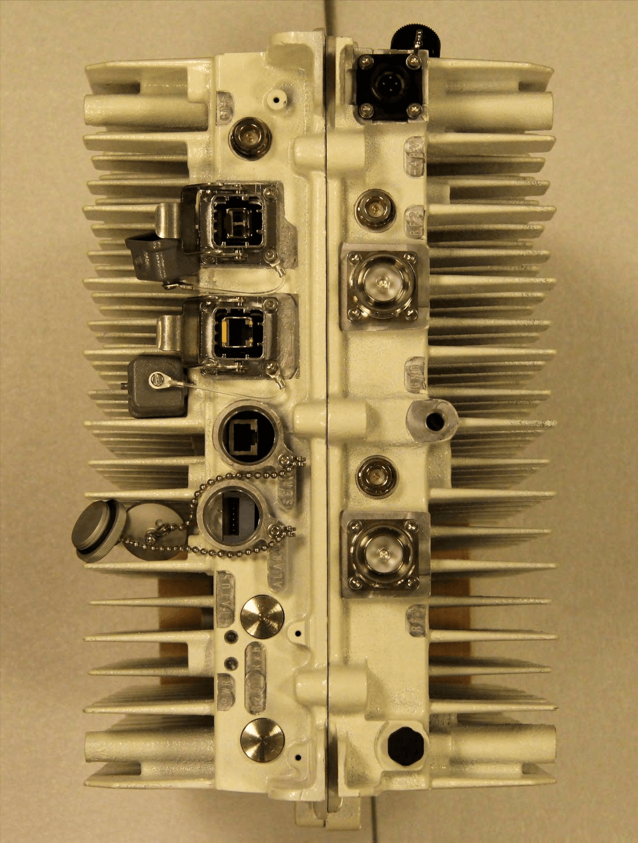
PKTNODEBAZY
Oct 21, 2015Band 12 LTE Base Station
Equipment Class
TNB - Licensed Non-Broadcast Station Transmitter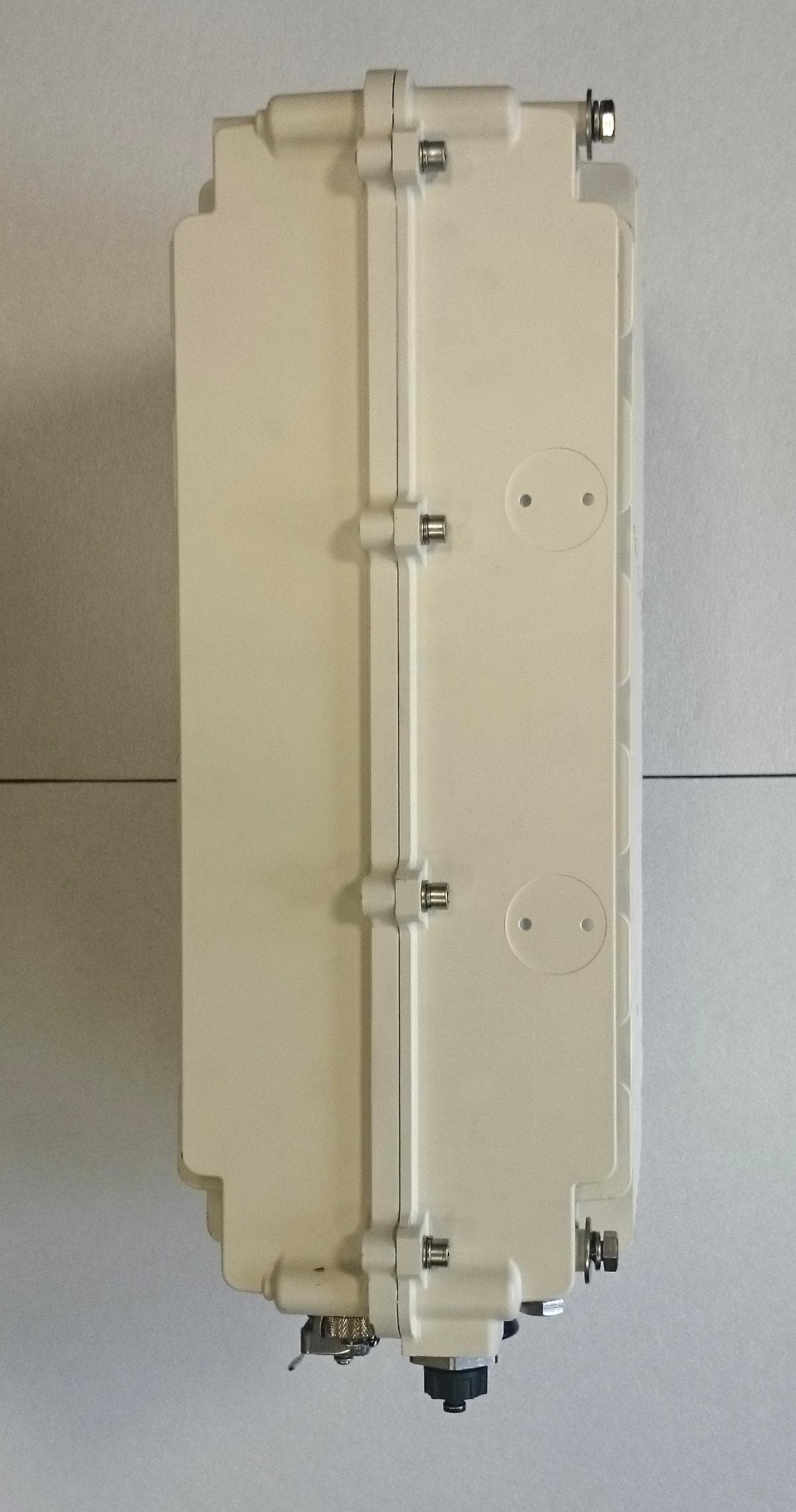
PKTNODEBBBK
Mar 23, 2015Band 14 LTE Base Station
Equipment Class
TNB - Licensed Non-Broadcast Station Transmitter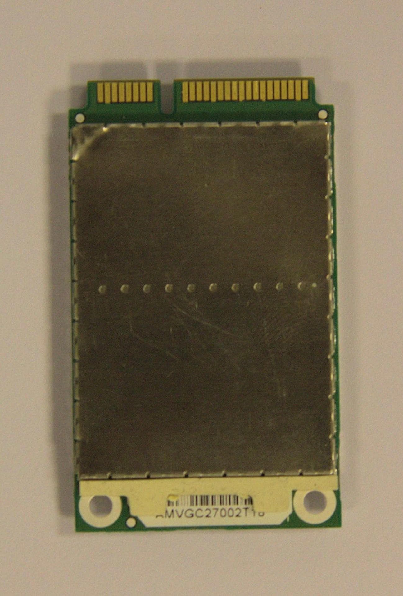
PKTPEMAMW1
Apr 03, 2014Broadband PCI Express Mini Module
Equipment Class
TNB - Licensed Non-Broadcast Station Transmitter
PKTUSBSTKARM
Dec 02, 2012LTE Band 12 USB Stick Modem
Equipment Class
TNB - Licensed Non-Broadcast Station Transmitter
PKTNODEBAQQ
Oct 03, 20123GPP Band 12 LTE Base Station
Equipment Class
TNB - Licensed Non-Broadcast Station Transmitter