PKTUSBSTKAGJ700 MHz TD-CDMA USB STick Modem
General Dynamics Broadband, Inc.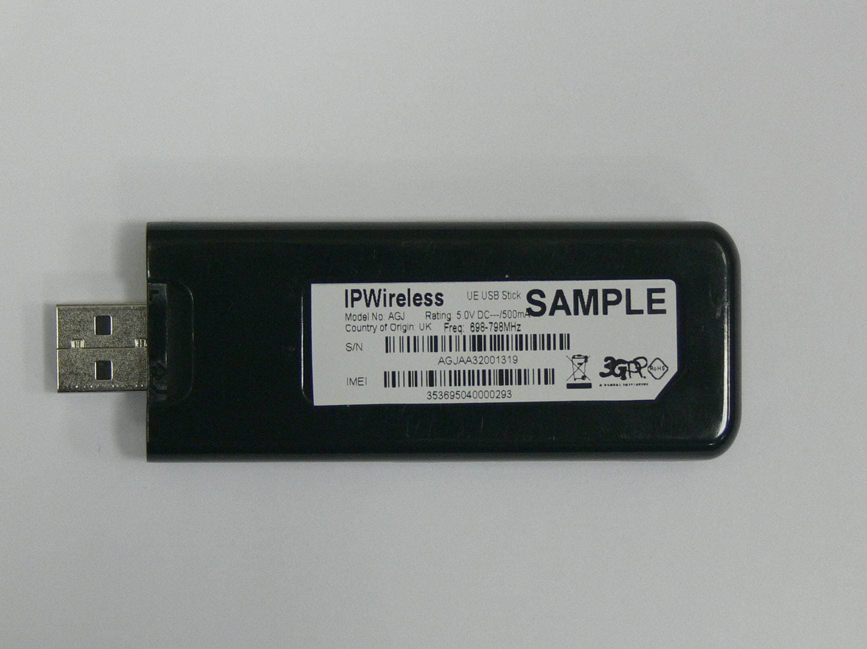
Click to zoom
Application Details
- Equipment Class
- JBP - Part 15 Class B Computing Device Peripheral
- Date of Grant
- Dec 16, 2010
- Application Purpose
- Original Equipment
- Date of Application
- Dec 15, 2010
- Equipment Note
- 700 MHz TD-CDMA USB STick Modem
- Country
- United States
Documents & Files
Document Text
Text extracted from the exhibit documents filed with the FCC. Open a document above to read the original.
Users Manual
Wireless Broadband Modem USB-Stick-Modem Quick Start Guide Important Notes: Read through the entire Quick Start Guide prior to beginning installation, paying particular attention to Safety and Care instructions. Run the installation software provided before connecting the USB Stick Modem to the computer. The installation software will instruct the user when to insert the USB-Modem into the computer. If you wish to disconnect the USB Stick Modem from the computer it is important to first make it safe for removal. Do this by clicking on the icon in the toolbar on the lower right of the screen and selecting STOP. Caution: This USB modem is approved for use in normal size laptop computers only (typically with 12 inch or larger display screens). To comply with FCC RF exposure requirements, this modem should not be used in configurations that cannot maintain a distance of at least 5mm (approximately 0.2 inch) from users and bystanders. Antennae (internal) Status Indicator SIM Card Tray (beneath USB Connector - if fitted) USB Connector (Cap removed) - 2 - Getting Started This Quick Start Guide gives basic installation and configuration instructions. Follow the instructions on the following pages to install the USB Stick Modem client software and driver files, before connecting the modem to the computer and then perform on-line registration, if applicable. Refer to the User Guide for the complete installation, upgrade and configuration procedures. Be sure to complete each of the following steps outlined below before moving on to the next step. SIM Card (if required) You have been supplied with a username and password to be used when connecting to the TDD network. The SIM may not always be required when authenticating TDD networks, check with your service provider. The SIM card is inserted directly into the modem below the USB connector, there is no SIM tray. Before removing the SIM card from the Modem, it is good practice and recommended that a safe hardware removal procedure is always followed for the Modem device. Disconnect and close the Client Software application. To remove the USB Stick Modem, first locate the “Safely Remove Hardware” icon, shown above, from the notification area usually to the right of the task bar. Using the mouse, left click on the icon. A “Safely remove ...” notification will be displayed similar to the one below. Click on the IPWireless Network Adapter to safely power off the adapter. Note: If the modem is in use i.e. connected to a network or the Client Software is open and displaying status, you will see a notification informing you that it is not possible to remove the adapter. Ensure that the Client Software is disconnected and closed before a safe removal. To connect to the TDD network you must first enter your username and password details in the Client Software using the Change User Details button near the bottom of the Application. When connected the Client Software will minimize to the notification bar next to the clock. The application can be restored by double clicking on this icon shown below. - 3 - Step 1. Install Client Software and USB Stick Modem Drivers Follow the instructions according to your installed operating system. Where no CD is provided for installation, your service provider shall provide the client installation software and necessary drivers. Windows 2000™ You must log in with administrative privileges 1. Where a CD is provided for the installation, close any programs that may be running and insert the CD into the CD-ROM drive on your computer. If the CD does not autorun and display a start screen, select Start->Run and enter d:\Setup.exe where d is your CD-ROM drive letter. 2. The Installation Setup Wizard will then prompt you through each step of the installation. (Use the Next> and <Back buttons to navigate the wizard and click Finish on the final screen). 3. When you reach the License Agreement screen, the installation will not proceed further unless you accept the terms of the License Agreement. 4. The installation software will then copy the Client Software and USB Stick Modem driver files onto your computer from the installation CD. 5. When the transfer of files to the computer is complete, you will be asked to plug the USB Stick Modem into your computer. Windows Vista™, Windows XP™ You must log in with administrative privileges 1. Close any programs that may be running and insert the CD into the CD-ROM drive on your computer. If the CD does not autorun and display a start screen, select Start->Run and enter d:\Setup.exe where d is your CD-ROM drive letter. 2. The Installation Setup Wizard will then prompt you through each step of the installation. (Use the Next> and <Back buttons to navigate the wizard and click Finish on the final screen). 3. When you reach the License Agreement screen, the installation will not proceed further unless you accept the terms of the License Agreement. 4. The installation software will then copy the Client Software and USB Stick Modem driver files onto your computer from the installation CD. 5. When the transfer of files to the computer is complete, you will be asked to plug the USB Stick Modem into your computer. Note: Where no CD is provided for installation, your service provider shall provide the client installation software and necessary drivers. - 4 - Step 2. Insert the USB Stick Modem and Obtain the Best Radio Signal Fit the SIM or USIM card, if one has been provided, into the SIM slot in the USB Stick Modem, observing the correct orientation and with the gold contacts on the SIM/USIM face down. Connnect the USB Stick Modem into a USB port on your computer either directly or using the cable supplied. The Modem will draw the power it needs to operate from the computer. The red power on indicator will glow steady after a few seconds to indicate that it is ready for operation. To obtain the best signal strength position the USB Stick Modem near a window. If connection fails with low signal strength …
Text truncated - open the document above for the full version.
Users Manual
Addendum Exposure to Radio Frequency Signals The following information includes important safety guidelines regarding exposure to radio frequency (RF) signals and the use of electronic devices. Your modem is a low power radio transmitter and receiver. When it is ON, it receives and also sends out RF signals. The USB Stick Modem has been evaluated against the Specific Absorption Rate (SAR) limits defined by the FCC for devices of this type. The highest reported SAR values for the USB Stick modems comply with the 1.6W/kg averaged over 1g limit. The highest SAR value measured for modems with FCC ID: PKTUSBSTKADT is 1.50W/kg averaged over 1g, the highest SAR value measured for modems with FCC ID: PKTUSBSTKAGJ is 0.97W/kg averaged over 1g. This USB modem is approved for use in normal size laptop computers only (typically with 12 inch or larger display screens). To comply with FCC RF exposure requirements, this modem should not be used in configurations that cannot maintain a distance of at least 5mm (approximately 0.2 inch) from users and bystanders. In configurations where the 5mm cannot be maintained consult your service provider for advice. Examples where this may occur are certain small laptops and tablet computers or configurations where the USB connectors on the host computer are unable to provide or ensure the necessary separation between the modem and its users or bystanders to satisfy the RF exposure compliance requirements. If you use the modem in accordance with these guidelines, the level of RF exposure will fall within the guidelines and the standards previously identified. October 2010 Part No. IPW-2461_issue1
ID Label/Location Info
FCC ID: PKTUSBSTKAGJ
Test Report
Reviewed by: FCC ID: PKTUSBSTKAGJ FCC Pt. 15B MEASUREMENT REPORT (CERTIFICATION) Quality Manager Test Report S/N: Test Dates: EUT Type: 0Y1008301447.PKT October 8, 2010 700MHz USB Stick Modem Page 1 of 18 © 2010 PCTEST Engineering Laboratory, Inc. REV 5.9CT 06/25/10 Applicant Name: Date of Testing: IP Wireless October 8, 2010 Unit 7 Greenways Business Park Test Site/Location: Bellinger Close, Chippenham PCTEST Lab, Columbia, MD, USA Wiltshire SN15 1BN Test Report Serial No.: 0Y1008301447.PKT FCC ID: PKTUSBSTKAGJ APPLICANT: IP Wireless Application Type: Certification EUT Type: 700MHz USB Stick Modem Model(s): AGJ FCC Rule Part(s): FCC Part 15 Subpart B FCC Classification: FCC Class B Digital Device (JBP) Test Procedure: ANSI C63.4-2003 The device bearing the FCC Identifier specified above has been shown to comply with the applicable technical standards as indicated in the measurement report and has been tested in accordance with the measurement procedures specified in ANSI C63.4-2003 (See Test Report). The results shown herein are also deemed satisfactory evidence of compliance with Industry Canada Interference-Causing Equipment Standard ICES-003. These measurements were performed with no deviation from the standards. Test results reported herein relate only to the item(s) tested. I authorize and attest to the accuracy of data. All measurements reported herein were performed by me or were made under my supervision and are correct to the best of my knowledge and belief. I assume full responsibility for the completeness of these measurements and vouch for the qualifications of all persons taking them. NVLAP accreditation does not constitute any product endorsement by NVLAP or any agency of the United States Government. This report must not be used by the customer to claim product certification, approval, or endorsement by NVLAP, NIST, or any agency of the Federal Government. PCTEST certifies that no party to this application has been denied the FCC benefits pursuant to Section 5301 of the Anti-Drug Abuse Act of 1988, 21 U.S.C. 862. PCTEST ENGINEERING LABORATORY, INC. 6660-B Dobbin Road, Columbia, MD 21045 USA Tel. 410.290.6652 / Fax 410.290.6554 http://www.pctestlab.com MEASUREMENT REPORT FCC Part 15B Reviewed by: FCC ID: PKTUSBSTKAGJ FCC Pt. 15B MEASUREMENT REPORT (CERTIFICATION) Quality Manager Test Report S/N: Test Dates: EUT Type: 0Y1008301447.PKT October 8, 2010 700MHz USB Stick Modem Page 2 of 18 © 2010 PCTEST Engineering Laboratory, Inc. REV 5.9CT 06/25/10 TABLE OF CONTENTS FCC Class B MEASUREMENT REPORT.....................................................................................3 1.0 INTRODUCTION ..............................................................................................................................4 1.1 SCOPE .................................................................................................................................................. 4 1.2 PCTEST TEST LOCATION ................................................................................................................... 4 2.0 PRODUCT INFORMATION..............................................................................................................5 2.1 EQUIPMENT DESCRIPTION ................................................................................................................ 5 2.2 OPERATION MODE.............................................................................................................................. 5 2.3 EMI SUPPRESSION DEVICE(S)/MODIFICATIONS ............................................................................. 5 2.4 LABELING REQUIREMENTS ............................................................................................................... 5 3.0 DESCRIPTION OF TEST.................................................................................................................6 3.1 EVALUATION PROCEDURE................................................................................................................ 6 3.2 CONDUCTED EMISSIONS ................................................................................................................... 6 3.3 RADIATED EMISSIONS........................................................................................................................ 7 4.0 SAMPLE CALCULATIONS ..............................................................................................................8 4.1 CONDUCTED EMISSION MEASUREMENT SAMPLE CALCULATION ............................................... 8 4.2 RADIATED EMISSION MEASUREMENT SAMPLE CALCULATION.................................................... 8 5.0 TEST EQUIPMENT CALIBRATION DATA ......................................................................................9 6.0 ENVIRONMENTAL CONDITIONS .................................................................................................10 7.0 TEST DATA ....................................................................................................................................11 7.1 SUMMARY .......................................................................................................................................... 11 7.2 TEST SUPPORT EQUIPMENT ........................................................................................................... 11 7.3 RADIATED MEASUREMENT DATA ................................................................................................... 12 7.4 LINE CONDUCTED MEASUREMENT DATA ..................................................................................... 13 8.0 CONCLUSION................................................................................................................................15 9.0 TEST SETUP PHOTOGRAPHS ....................................................................................................16 Reviewed by: FCC ID: PKTUSBSTKAGJ FCC Pt. 15B MEASUREMENT REPORT (CERTIFICATION) Quality…
Text truncated - open the document above for the full version.
Test Setup Photos
Reviewed by: FCC ID: PKTUSBSTKAGJ FCC Pt. 15B MEASUREMENT REPORT (CERTIFICATION) Quality Manager Test Report S/N: Test Dates: EUT Type: 0Y1008301447.PKT October 8, 2010 700MHz USB Stick Modem Page 16 of 18 © 2010 PCTEST Engineering Laboratory, Inc. REV 5.9CT 06/25/10 9.0 TEST SETUP PHOTOGRAPHS Reviewed by: FCC ID: PKTUSBSTKAGJ FCC Pt. 15B MEASUREMENT REPORT (CERTIFICATION) Quality Manager Test Report S/N: Test Dates: EUT Type: 0Y1008301447.PKT October 8, 2010 700MHz USB Stick Modem Page 17 of 18 © 2010 PCTEST Engineering Laboratory, Inc. REV 5.9CT 06/25/10 Reviewed by: FCC ID: PKTUSBSTKAGJ FCC Pt. 15B MEASUREMENT REPORT (CERTIFICATION) Quality Manager Test Report S/N: Test Dates: EUT Type: 0Y1008301447.PKT October 8, 2010 700MHz USB Stick Modem Page 18 of 18 © 2010 PCTEST Engineering Laboratory, Inc. REV 5.9CT 06/25/10
Contact Information
Applicant
Joseph Cheung
Technical Contact
PCTEST Engineering Laboratory, Inc.Randy Ortanez
[email protected]410-290-6652
6660-B Dobbin Road · Columbia, Maryland · United States
Test Firm
PCTEST Engineering Laboratory, Inc.Randy Ortanez
Technical Specifications
| # | Rule Parts | Frequency Range | Power Output |
|---|---|---|---|
| 1 | 15B | - | - |
Other Applications from General Dynamics Broadband, Inc.
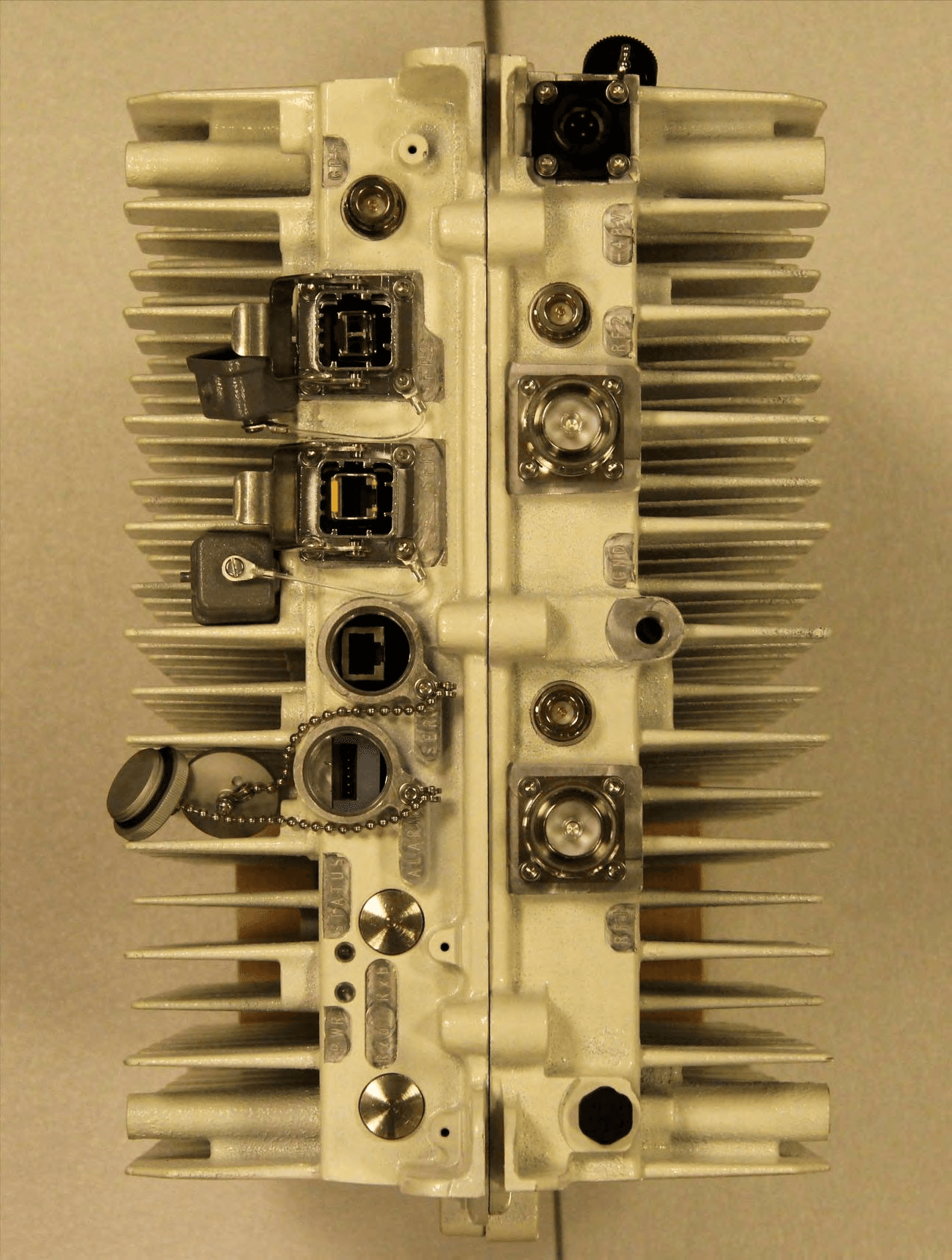
PKTNODEBAZY
Oct 21, 2015Band 12 LTE Base Station
Equipment Class
TNB - Licensed Non-Broadcast Station Transmitter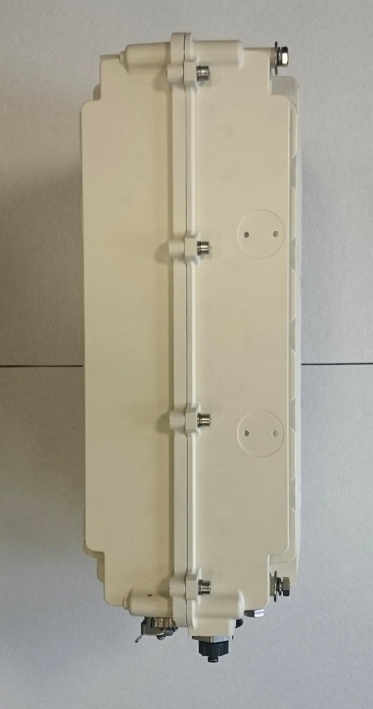
PKTNODEBBBK
Mar 23, 2015Band 14 LTE Base Station
Equipment Class
TNB - Licensed Non-Broadcast Station Transmitter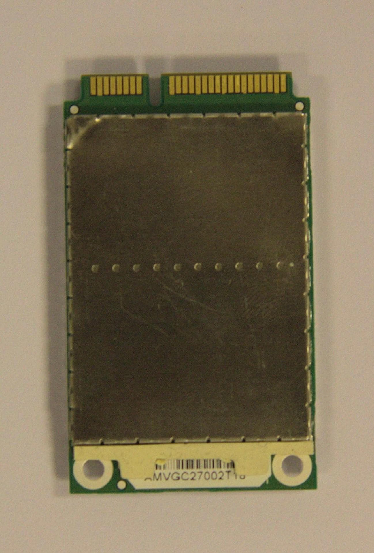
PKTPEMAMW1
Apr 03, 2014Broadband PCI Express Mini Module
Equipment Class
TNB - Licensed Non-Broadcast Station Transmitter
PKTUSBSTKARM
Dec 02, 2012LTE Band 12 USB Stick Modem
Equipment Class
TNB - Licensed Non-Broadcast Station Transmitter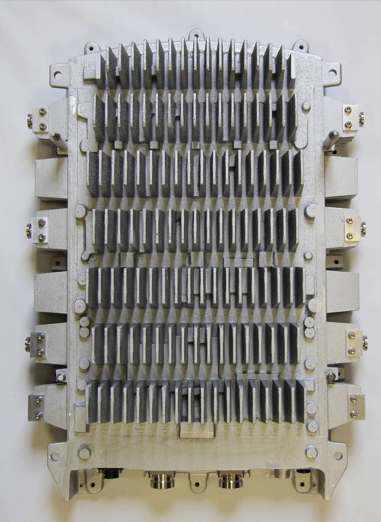
PKTNODEBAQQ
Oct 03, 20123GPP Band 12 LTE Base Station
Equipment Class
TNB - Licensed Non-Broadcast Station Transmitter