PKW-BEFW11S4V32Wireless Access Point Router with 4-Port Switch
Cisco-Linksys, LLC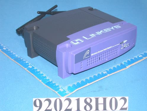
Click to zoom
Application Details
- Equipment Class
- DTS - Digital Transmission System
- Date of Grant
- Apr 13, 2003
- Application Purpose
- Original Equipment
- Date of Application
- Apr 08, 2003
- Equipment Note
- Wireless Access Point Router with 4-Port Switch
- Frequency Range
- 2412.00000000 - 2462.00000000
- Company
- Cisco-Linksys, LLC
- Country
- United States
Documents & Files
Document Text
Text extracted from the exhibit documents filed with the FCC. Open a document above to read the original.
Users Manual
[email protected] www.adt.com.tw ADVANCE DATA TECHNOLOGY CORPORATION FEDERAL COMMUNICATIONS COMMISSION DECLARATION OF CONFORMITY (DoC) FOR THE FOLLOWING EQUIPMENT: PRODUCT NAME: Wireless Access Point Router with 4-Port Switch MODEL NO: BEFW11S4 V3.2 TRADE NAME: Linksys IS HEREWITH CONFIRMED AND FOUND TO COMPLY WITH THE REQUIREMENTS OF CFR 47 PART 15 REGULATION. THE RESULTS OF ELECTROMAGNETIC EMISSION EVALUATION ARE SHOWN IN THE REPORT NO : RF920218H02 THIS DEVICE COMPLIES WITH PART 15 OF THE FCC RULES. OPERATION IS SUBJECT TO THE FOLLOWING TWO CONDITIONS: (1) THIS DEVICE MAY NOT CAUSE HARMFUL INTERFERENCE AND, (2) THIS DEVICE MUST ACCEPT ANY INTERFERENCE RECEIVED, INCLUDING INTERFERENCE THAT MAY CAUSE UNDESIRED OPERATION. THE FOLLOWING LOCAL MANUFACTURER/IMPORTER IS RESPONSIBLE FOR THIS DECLARATION ManufacturerUSA Local Representative Company name: THE LINKSYS GROUP, INC. To Be Determined. Address: 17401 Armstrong Ave. Irvine, CA 92614 Contact Person: Frank Hung Title: Product Engineer Tel/Fax:
Users Manual
The LAN Indicators WLAN ActGreen. This LED indicates wireless activity. WLAN LinkGreen. This LED indicates that the Router’s wireless func- tions have been enabled through the Web-based utility. PowerGreen. This LED indicates that the Router’s power is on. Link/ActGreen. This LED serves two purposes. When this LED is lit continuously, this indicates that the Router is connected to a device through the corresponding port (1, 2, 3, or 4). A blink- ing LED indicates that the Router is actively sending or receiving data over that port. When the Uplink Port is in use, the LED for Port 4 will be lit continuously. 6 The Wireless Access Point Router’s LEDs TThhee RReesseett BBuuttttoonn Pressing the Reset Button and holding it in for a few seconds will clear all of the Router’s data and restore the factory defaults. This should be done only if you are experiencing heavy routing problems, and only after you have exhausted all of the other troubleshooting options. By resetting the Router, you run the risk of creating conflicts between your PCs’ actual IP Addresses and what the Router thinks their IP Addresses should be. You may be forced to reboot each network PC. If the Router locks up, simply press the reset button or power it down for three to five seconds by removing the power cable from the Router’s Power Port. Leaving the power off for too long could result in the loss of network connections. Figure 1-2 The Router’s rear panel (as shown in Figure 1-1) is where all of its connections are made. WA NThe WAN (Wide Area Network) Port is where you will con- nect your cable or DSL modem with an Ethernet cable. Your modem connection will not work from any other port. Ports 1-4These four LAN (Local Area Network) ports are where you will connect networked devices, such as PCs, print servers, and any other Ethernet devices you want to put on your net- work. If Port 4 is being used, the Uplink Port will not work. UplinkThe Uplink Port is where you can expand your network by connecting to another switch or hub. Uplinking to another switch or a hub is done by simply running a cable from the Uplink Port to the other device. The Uplink Port is shared with Port 4. If the Uplink port is being used, Port 4 will not work. PowerThe Power Port is where you will connect the included AC Power adapter. Antenna JacksThe Antenna Jacks are where the included antennas are con- nected. Figure 1-1 The Wireless Access Point Router’s Ports Instant Wireless TM Series Wireless Access Point Router with 4-Port Switch 5 Chapter 2: Connecting the Router Before plugging everything together, it’s always a good idea to have everything you’ll need to get the Router up and running. Depending upon how you config- ure the Router in Chapter 4: Configuring the Router, you may need some of the following values from your ISP: When connecting through a Static IP connection, be sure to have 1) Your broadband-configured PC’s fixed Internet IP Address, 2) Your broadband- configured PC’s Computer Name and Workgroup Name, 3) Your Subnet Mask, 4) Your Default Gateway, and 5) Your Primary DNS IP address. When connecting through a PPPoE connection, be sure to have 1) Your PPPoE User Name and 2) Your PPPoE Password. The installation technician from your ISP should have left this information with you after installing your broadband connection. If not, you can call your ISP to request the data. Once you have the above values, you can begin the Router’s installation and setup. Once you are sure that you have the above values on hand, you can begin the Installation and Setup of the Router. 1. Power everything down, including your PCs, your cable or DSL modem and the Router. 2. Connect an Ethernet cable from one of your PC’s Ethernet ports to one of the Router’s LAN ports (as shown in Figure 2- 1). Do the same with all the PCs you wish to connect to the Router. (LAN Port 4 will become inactive if you use the Uplink port.) In addition to accessing the Router through an Ethernet connection, a wireless connec- Before You Start Full/ColGreen. This LED also serves two purposes. When this LED is lit continuously, the connection made through the corre- sponding port is running in Full Duplex mode. A blinking LED indicates that the connection is experiencing collisions. Infrequent collisions are normal. If this LED blinks too often, there may be a problem with your connection. Refer to the Troubleshooting Appendix if you think there is a prob- lem. 100Orange. This LED indicates when a successful 100Mbps connection is made through the corresponding port. The WAN Indicators LinkGreen. This LED indicates a connection between the Router and your broadband device or network. ActGreen. This LED blinks when the Router is sending or receiving data over the broadband (WAN) port. DiagRed. This LED indicates the Router’s self-diagnosis mode during boot-up and restart. It will turn off upon completing the diagnosis. If this LED stays on for an abnormally long period of time, refer to the Troubleshooting Appendix. 7 Connecting Your Hardware Together and Booting Up Figure 2-1 Instant Wireless TM Series Wireless Access Point Router with 4-Port Switch 8 For Wireless Connections:In addition to accessing the Router through an Ethernet connection, a wireless connection can be used to access the Router. After powering on the Router and connecting it to your modem, enter the Router’s IP Address in the Address field of your wireless PC’s web-browser as follows: http://192.168.1.1and press Enter. IImmppoorrttaanntt:: The Wireless Access Point Router with 4-Port Switch is configured by default to work out of the box with all Linksys Wireless Adapters. If you have changed the defaults on your Linksys Wireless Adapters, or are using other wireless adapters, you must temporar- ily change your wireless adapter settings to: (SSID = linksys) in order to initially access the Router wirelessly. After you have accessed the Router with the default settings, you can change the router settings to c…
Text truncated - open the document above for the full version.
Users Manual
2. Select the Configuration tab and highlight the TCP/IP linefor the applicable Ethernet adapter (as shown in Figure 3-1). If the word TCP/IPappears by itself, select that line. (Note: If there is no TCP/IP line list- ed, refer to your Ethernet adapter’s documentation to install TCP/IP now.) Then, click the Propertiesbutton. 3. Click the IP Addresstab and select Obtain an IP address automatically(as shown in figure 3-2). 4. Click the Gatewaytab and verify that the Installed Gateway field is blank. Click the OKbutton. Chapter 3: Configuring the PCs These instructions will help you configure each of your computers to commu- nicate with the Router. To do this, you will need to configure your PC’s network settings to obtain an IP (or TCP/IP) address automatically. Computers use IP addresses to commu- nicate with each other across a network or the Internet. You will need to know which operating system your computer is running, such as Windows 95, 98, Millennium, 2000, or XP. You can find out by clicking the Startbutton and then selecting the Settingsoption. (If your Start menu does- n’t have a Settings option, you’re running Windows XP. You can select the Control Panel directly from the Start Menu.) Then, click Control Paneland double-click the Systemicon. Click the Cancel button when done. Once you know which Windows operating system you are running, follow the directions in this step for your computer’s operating system. If you PC is not configured with the TCP/IP protocol, you will need to do this for each com- puter you are connecting to the Router. The next few pages tell you, step by step, how to configure your TCP/IP set- tings based on the type of Windows operating system you are using. Once you've configured your computers, continue to Chapter 4: Configuring the Router. 1. Click the Startbutton, click Settingsand open the Control Panel. From there, double-click the Networkicon to open the Network screen. 12 Overview Configuring Windows 95, 98, and Millennium PCs Figure 3-1 Figure 3-2 Instant Wireless TM Series Wireless Access Point Router with 4-Port Switch 11 5. Click the OKbutton again. Windows may ask you for the original Windows installation disk or additional files. Supply them by pointing to the correct file location, e.g., D:\win98, D:\win9x, c:\windows\options\cabs, etc. (This assumes that “D” is the letter of your CD-ROM drive). 6. If Windows asks you to restart your PC, click the Ye sbutton. If Windows does not ask you to restart, restart your computer anyway. Repeat steps 1-6 for each PC on your network. When all of your PCs are configured, proceed to Chapter 4: Configuring the Router. 1. Click the Startbutton, click Settingsand open the Control Panel. From there, double-click the Network and Dial-up Connectionsicon. This will display the Network screen. 2. Select the Local Area Connectionicon for the applicable Ethernet adapter (usually it is the first Local Area Connection listed). 3. When the Local Area Connection Status screen appears, click the Propertiesbutton. (See Figure 3-3.) 4. Select Internet Protocol (TCP/IP)(as shown in Figure 3-4) and click the Propertiesbutton. 5. Select Obtain an IP address automatically and verify that Obtain DNS server address automaticallyis select- ed (as shown in Figure 3-5). Then, click the OK button and click the OK button on the subse- quent screens to com- plete the PC’s configura- tion. Repeat steps 1-5 for each PC on your network. When all of your PCs are configured, proceed to Chapter 4: Configuring the Router. Configuring Windows 2000 PCs Figure 3-3 Figure 3-4 Figure 3-5 Instant Wireless TM Series Wireless Access Point Router with 4-Port Switch 1314 © Copyright 2002 Linksys, All Rights Reserved. Printed in the USA. http://www.linksys.com
Cover Letter(s)
American Telecommunications Certification Body Inc. 6731 Whittier Ave, McLean, VA 22101 March 27, 2003 RE: Linksys Group Inc. FCC ID: PKW-BEFW11S4V32 After a review of the submitted information, I have a few comments on the above referenced Application. 1) Please provide a detailed close up photograph of the RF section of the device with the sub-shields removed. Additionally, if the RF portion is a separate Card, photographs of the main board with the card removed, and also bottom views of the Card itself must be provided. (Note block diagram shows the RF as a separate Card). 2) Please provide a schematic for the transmitter board. This is required by 2.1033(b)(5) for the RF section. As an alternative, you may provide a parts list that lists the RF board as a part provided by another manufacturer. Depending on the items provided, the letter of confidentiality may need to be adjusted to cover the parts list. 3) The users manual page 105 states that the output power is 19 dBm. However the maximum measured output power was 16.4 dBm. The output power should be consistent to within 0.5 dB throughout the application. Please correct the users manual. 4) The required statements given in 15.21 should be added to the users manual. Additionally, the users manual is missing information regarding RF exposure statements. Please provide a corrected users manual. 5) Note: We are also awaiting an updated users manual as Bill Graff had discussed with you due to the large size of the files provided. 6) The delta's given on page 45 of the test report are incorrect. For 2.39 GHz, it appears that the delta should be 62.38, and for 2.4835 GHz it should be 60.23. Additionally, the calculations should be shown for both bandedges. Please correct. Timothy R. Johnson Examining Engineer mailto: [email protected] The items indicated above must be submitted before processing can continue on the above referenced application. Failure to provide the requested information may result in application termination. Correspondence should be considered part of the permanent submission and may be viewed from the Internet after a Grant of Equipment Authorization is issued. Please do not respond to this correspondence using the email reply button. In order for your response to be processed expeditiously, you must submit your documents through the AmericanTCB.com website. Also, please note that partial responses increase processing time and should not be submitted. Any questions about the content of this correspondence should be directed to the sender.
Cover Letter(s)
Hi, Timothy R. Johnson Sorry! For your question in attached comment: 1) The RF portion is not a separate card, it's on main board. We will mail you the revised block diagram and the "close" photo with sub-shield removed! 2) The schematic for the transmitter board will be mail to you when we receive from our client. 3)~5) Done! Uploaded new revised manual. 6) Done! Uploaded new revised report. Best Regards, Amanda Chu / ¦¶ªÚ½Ë (Embedded image moved to file: pic07441.gif) ~~~~~~~~~~~~~~~~~~~~~~~~~~~~~~~~ Certification Specialist ADT Corp. (Hsin Chu Office) TEL: 03-5935343 FAX: 03-5935342 ~~~~~~~~~~~~~~~~~~~~~~~~~~~~~~~~ ----- Âà§eªÌ Amanda Chu/ADT ©ó 2003/04/01 02:22 PM ----- Eric Lin(ªL¤å Ùy/·s¦ËÅçÃÒªA ¦¬¥ó¤H¡G Amanda Chu/ADT@ADT, Bruce Shiau/ADT@ADT, Cherry Chen/ADT@ADT °È³B) °Æ¥»§Û°e¡G Alan Lane/ADT@ADT ¥D¦®¡G Review of Linksys Group Inc., FCC ID: PKW- BEFW11S4V32 2003/03/28 09:13 AM Dear Amanda, Please check the attached letter items, it seems a lot of questions that have to response. Please collect the answer and reply to Timothy, Best Regards, To: [email protected] Cc: [email protected], [email protected], [email protected], [email protected] Subject: Review of Linksys Group Inc., FCC ID: PKW-BEFW11S4V32 4/4/2003file://C:\DOCUME~1\TIMOTH~1.JOH\LOCALS~1\Temp\eud49.htm ªL¤åÙy / Eric Lin ADT Corp. Hsinchu Div. TEL: 886-3-593-5343 FAX: 886-3-593-5342 e-mail: [email protected] web-site: www.adt.com.tw (Embedded image moved to file: pic09512.gif)(Embedded image moved to file: pic30145.gif) (Embedded image moved to file: pic18060.gif) ----- Âà§eªÌ Eric Lin/ADT ©ó 2003/03/28 09:16 AM ----- "Timothy R. Johnson" ¦¬¥ó¤H¡G [email protected] <tjohnson@Americ °Æ¥»§Û°e¡G anTCB.com> ¥D¦®¡G Review of Linksys Group Inc., FCC ID: PKW- BEFW11S4V32 2003/03/28 04:37 AM Eric, Attached are comments regarding review of this application. Please provide information as soon as possible. Thank You, Timothy R. Johnson NARTE Certified EMC Engineer No. EMC-002205-NE email: [email protected] alternate email: [email protected] (See attached file: ATCB Comment_ 032703.pdf) 4/4/2003file://C:\DOCUME~1\TIMOTH~1.JOH\LOCALS~1\Temp\eud49.htm pic074411.gif pic095121.gif pic301451.gif pic180601.gif =big5BQVRDQiBDb21tZW50XyAwMzI3MDMucGRm=1.pdf 4/4/2003file://C:\DOCUME~1\TIMOTH~1.JOH\LOCALS~1\Temp\eud49.htm
External Photos
Page 1 CONSTRUCTION PHOTOS OF EUT Page 2
ID Label/Location Info
(Fig. 1) FCC ID: PKW-BEFW11S4V32 FCC LABEL LOCATION The label will be permanently affixed at a conspicuous location on the device. Label
Internal Photos
Page 1 CONSTRUCTION PHOTOS OF EUT Page 2 Page 3 Page 4 Page 5 Page 6 Page 7 Page 8 Page 9
Operational Description
FCC ID: PKW-BEFW11S4V32 Report No.: 920218H02 ADT No.: 920218H02 Operational Description The transmitter of the EUT (Wireless Access Point Router with 4-Port Switch) is powered by adapter. The antenna used in this product is Detachable Antenna with TNC connector. Under normal use condition, the user has to keep at least 20cm separation distance between radiator and the body of the user. The other instruction, please have a look at the users manual. DSSS Information This device is Direct Sequence Spread Spectrum, the data is mixed by pseudorandom code which is an orthogonal code. The mixed data is digital modulated by DBPSK and DQPSK technique depends on the data rates. The CCK coding is applied for increasing the data rate, and also the processing gain will be increased. The bit rates are 1,2,5.5,11Mbps.
RF Exposure Info
FCC ID: PKW-BEFW11S4V32 ADT No.: 920218H02 RF EXPOSURE REPORT REPORT NO.: RF920218H02 MODEL NO.: BEFW11S4 V3.2 ACCORDING: FCC Guidelines for Human Exposure IEEE C95.1 APPLICANT: The Linksys Group, INC. ADDRESS: 17401 Armstrong Ave. Irvine, CA 92614 ISSUED BY: Advance Data Technology Corporation LAB LOCATION: No. 81-1, Lu Liao Keng, 9 Ling, Wu Lung Tsuen, Chiung Lin Hsiang, Hsin Chu Hsien, Taiwan, R.O.C. 0536 ILAC MRA Lab Code: 200376-0 FCC ID: PKW-BEFW11S4V32 ADT No.: 920218H02 RF Exposure Measurement (Mobile Device) 1. Introduction 2.4 GHz frequency band is regarded specially as a dangerous band for its heating harmfulness to the human body. That’s why microwave oven is operating in this frequency band. The manufacturer whose product is working in this frequency band is obligatory to prove the harmfulness of his product. In this document, we try to prove the safety of radiation harmfulness to the human body for our product. The limit for Maximum Permissible Exposure (MPE) specified in FCC 1.1310 is followed. The Gain of the antenna used in this product is measured in a Fully Anechoic Chamber (FAC), and the maximum total power input to the antenna is measured. Through the Friis transmission formula and the maximum gain of the antenna, we can calculate the distance, away from the product, where the limit of MPE is reached. 2. Classification The antenna of the product, under normal use condition, is at least 20 cm away from the body of the user. Warning statement for keeping 20 cm separation distance and the prohibition of operating next to a person has been printed on the users manual. So, this product is classified as the Mobile Device. 3. RF Exposure Limit According to FCC 1.1310: The criteria listed in the following table shall be used to evaluate the environmental impact of human exposure to radio-frequency (RF) radiation as specified in 1.1307(b). FCC ID: PKW-BEFW11S4V32 ADT No.: 920218H02 LIMITS FOR MAXIMUM PERMISSIBLE EXPOSURE (MPE) Frequency Range (MHz) Electric Field Strength (V/m) Magnetic Field Strength (A/m) Power Density (mW/cm 2 ) Average Time (minutes) (A)Limits For Occupational / Control Exposures 30-30061.40.1631.06 300-1500......F/3006 1500-100,000......56 (B)Limits For General Population / Uncontrolled Exposure 30-30027.50.0730.230 300-1500......F/150030 1500-100,000......1.030 F = Frequency in MHz 4. Friis Formula Friis transmission formula : Pd = (Pout*G) / (4*pi*r 2 ) where Pd = power density in mW/cm 2 Pout = output power to antenna in mW G = gain of antenna in linear scale Pi = 3.1416 R = distance between observation point and center of the radiator in cm Pd is the limit of MPE, 1 mW/cm 2 . If we know the maximum Gain of the antenna and the total power input to the antenna, through the calculation, we will know the distance r where the MPE limit is reached. Ref. : David K. Cheng, Field and Wave Electromagnetics, Second Edition, Page 640, Eq. (11-133). 5. EUT Operating condition The software provided by Manufacturer enabled the EUT to transmit and receive data at lowest, middle and highest channel individually. FCC ID: PKW-BEFW11S4V32 ADT No.: 920218H02 6. Test Results 6.1 Antenna Gain The maximum Gain measured in Fully Anechoic Chamber is 2Bi or 1.58 (numeric). 6.2 Output Power Into Antenna & RF Exposure Distance : CHANNEL CHANNEL FREQUENCY (MHz) OUTPUT POWER TO ANTENNA (mW) MINIMUM ALLOWABLE DISTANCE ( r ) FROM SKIN (Centi-Meter) 1241239.452.23 6243740.741.77 11246243.152.33 The minimum allowable distance is very close to the enclosure of the antenna. So, the user has no need to worry about the harmfulness of radiation. But it is recommended to always keep, at least, 20 cm separation distance with the antenna.
Test Report
FCC ID: PKW-BEFW11S4V32 Report No.: RF920218H021Issued: Mar. 24, 2003 ADT No. 920218H02 FCC TEST REPORT REPORT NO.: RF920218H02 MODEL NO.: BEFW11S4 V3.2 RECEIVED: Feb. 18, 2003 TESTED: Feb. 19 to Mar. 11, 2003 APPLICANT: The Linksys Group, INC. ADDRESS: 17401 Armstrong Ave. Irvine, CA 92614 ISSUED BY: Advance Data Technology Corporation LAB LOCATION: No. 81-1, Lu Liao Keng, 9 Ling, Wu Lung Tsuen, Chiung Lin Hsiang, Hsin Chu Hsien, Taiwan, R.O.C. This test report consists of 51 pages in total. It may be duplicated completely for legal use with the approval of the applicant. It should not be reproduced except in full, without the written approval of our laboratory. The client should not use it to claim product endorsement by CNLA, NVLAP or any government agencies. The test results in the report only apply to the tested sample. 0536 ILAC MRA Lab Code: 200376-0 FCC ID: PKW-BEFW11S4V32 Report No.: RF920218H022Issued: Mar. 24, 2003 ADT No. 920218H02 Table of Contents 1CERTIFICATION......................................................................................................4 2SUMMARY OF TEST RESULTS...........................................................................5 3GENERAL INFORMATION....................................................................................6 3.1GENERAL DESCRIPTION OF EUT.....................................................................6 3.2DESCRIPTION OF TEST MODES.......................................................................7 3.3GENERAL DESCRIPTION OF APPLIED STANDARDS..................................7 3.4DESCRIPTION OF SUPPORT UNITS.................................................................8 4TEST TYPES AND RESULTS.............................................................................10 4.1CONDUCTED EMISSION MEASUREMENT....................................................10 4.1.1TEST INSTRUMENTS.............................................................................................10 4.1.2TEST PROCEDURES..............................................................................................11 4.1.3DEVIATION FROM TEST STANDARD....................................................................11 4.1.4TEST SETUP...........................................................................................................12 4.1.5EUT OPERATING CONDITIONS............................................................................13 4.1.6TEST RESULTS.......................................................................................................14 4.2RADIATED EMISSION MEASUREMENT.........................................................20 4.2.1LIMITS OF RADIATED EMISSION MEASUREMENT............................................20 4.2.2TEST INSTRUMENTS.............................................................................................21 4.2.3TEST PROCEDURES.............................................................................................22 4.2.4DEVIATION FROM TEST STANDARD...................................................................22 4.2.5TEST SETUP...........................................................................................................23 4.2.6EUT OPERATING CONDITIONS............................................................................23 4.2.7TEST RESULTS.......................................................................................................24 4.36dB BANDWIDTH MEASUREMENT.................................................................29 4.3.1LIMITS OF 6dB BANDWIDTH MEASUREMENT....................................................29 4.3.2TEST INSTRUMENTS.............................................................................................29 4.3.3TEST PROCEDURE................................................................................................30 4.3.4DEVIATION FROM TEST STANDARD...................................................................30 4.3.5TEST SETUP...........................................................................................................30 4.3.6EUT OPERATING CONDITIONS............................................................................30 4.3.7TEST RESULTS.......................................................................................................31 4.4MAXIMUM PEAK OUTPUT POWER.................................................................35 4.4.1LIMITS OF MAXIMUM PEAK OUTPUT POWER MEASUREMENT......................35 4.4.2INSTRUMENTS........................................................................................................35 4.4.3TEST PROCEDURES.............................................................................................36 4.4.4DEVIATION FROM TEST STANDARD...................................................................36 4.4.5TEST SETUP...........................................................................................................36 FCC ID: PKW-BEFW11S4V32 Report No.: RF920218H023Issued: Mar. 24, 2003 ADT No. 920218H02 4.4.6EUT OPERATING CONDITIONS............................................................................36 4.4.7TEST RESULTS.......................................................................................................37 4.4.8LIMITS OF POWER SPECTRAL DENSITY MEASUREMENT...............................38 4.4.9TEST INSTRUMENTS.............................................................................................38 4.4.10TEST PROCEDURE................................................................................................39 4.4.11DEVIATION FROM TEST STANDARD...................................................................39 4.4.12TEST SETUP...........................................................................................................39 4.4.13EUT OPERATING CONDITION...............................................................................39 4.4.14TEST RESULTS.......................................…
Text truncated - open the document above for the full version.
Test Setup Photos
FCC ID: PKW-BEFW11S4V32 Report No.: RF920218H0249Issued: Mar. 24, 2003 ADT No. 920218H02 5 PHOTOGRAPHS OF THE TEST CONFIGURATION CONDUCTED EMISSION TEST FCC ID: PKW-BEFW11S4V32 Report No.: RF920218H0250Issued: Mar. 24, 2003 ADT No. 920218H02 RADIATED EMISSION TEST
Contact Information
Applicant
Ms Jennifer Yu(Associate Engineer)
Technical Contact
Advance Data Technology CorporationEric Line
[email protected]+886-3-593-5343
81-1 Luliaoken, 9th Lin, Wulung Tsuen · Hsinchu · Taiwan
Non-Technical Contact
Advance Data Technology CorporationEric Lin
[email protected]+886-3-593-5343
Test Firm
Bureau Veritas CPS (H.K.) Ltd. Taoyuan BranchRichard Chen
Technical Specifications
| # | Rule Parts | Frequency Range | Power Output |
|---|---|---|---|
| 1 | 15C | 2.41 GHz - 2.46 GHz | 43.00 mW |
Other Applications from Cisco-Linksys, LLC

PKW-WMP54GV2
May 29, 2003Wireless-G PCI Adapter
Equipment Class
DTS - Digital Transmission System
PKW-BEFW11S4V4
May 21, 2003Wireless Access Point Router
Equipment Class
DTS - Digital Transmission System
PKW-WSB24-2
Apr 03, 2003Wireless Signal Booster
Equipment Class
DTS - Digital Transmission System
PKW-BEFCMUH4
Apr 01, 2003Cable Gateway
Equipment Class
DTS - Digital Transmission System
PKW-WCB54G
Mar 25, 2003Wireless-G CardBus Module
Equipment Class
DTS - Digital Transmission System