PKW-NWU11BWireless USB Network Adapter
Cisco-Linksys, LLC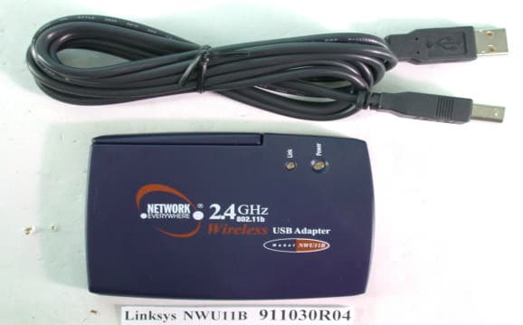
Click to zoom
Application Details
- Equipment Class
- DTS - Digital Transmission System
- Date of Grant
- Dec 04, 2002
- Application Purpose
- Original Equipment
- Date of Application
- Dec 04, 2002
- Equipment Note
- Wireless USB Network Adapter
- Frequency Range
- 2412.00000000 - 2462.00000000
- Company
- Cisco-Linksys, LLC
- Country
- United States
Documents & Files
Document Text
Text extracted from the exhibit documents filed with the FCC. Open a document above to read the original.
Users Manual
COPYRIGHT & TRADEMARKS Copyright © 2002 Network Everywhere. All rights reserved. Network Everywhere and theNetwork Everywhere logo are registered trademarks of The Linksys Group, Inc.Microsoft, Windows, and the Windows logo are registered trademarks of MicrosoftCorporation. All other companies and product names are trademarks of their respectivecompanies.Network Everywhere guarantees that every Wireless USB Adapter will be free from phys-ical defects in material and workmanship for one year from the date of purchase, whenused within the limits set forth in the Specifications section of this User Guide. If the prod-uct proves defective during this warranty period, call Network Everywhere TechnicalSupport in order to obtain a Return Authorization number. BE SURE TO HAVE YOURPROOF OF PURCHASE ON HAND WHEN CALLING. When returning a product, markthe Return Authorization number clearly on the outside of the package and include acopy of your original proof of purchase. RETURN REQUESTS CANNOT BE PROCESSEDWITHOUT PROOF OF PURCHASE. All customers located outside of the United Statesof America and Canada shall be held responsible for shipping and handling charges.IN NO EVENT SHALL NETWORK EVERYWHERE’S LIABILITY EXCEED THE PRICE PAIDFOR THE PRODUCT FROM DIRECT, INDIRECT, SPECIAL, INCIDENTAL, OR CONSE-QUENTIAL DAMAGES RESULTING FROM THE USE OF THE PRODUCT, ITS ACCOM-PANYING SOFTWARE, OR ITS DOCUMENTATION. NETWORK EVERYWHERE OFFERSNO REFUNDS FOR ITS PRODUCTS. Network Everywhere makes no warranty or repre-sentation, expressed, implied, or statutory, with respect to its products or the contents oruse of this documentation and all accompanying software, and specifically disclaims itsquality, performance, merchantability, or fitness for any particular purpose. NetworkEverywhere reserves the right to revise or update its products, software, or documenta-tion without obligation to notify any individual or entity. Please direct all inquiries to:Network Everywhere P.O. Box 18558, Irvine, CA 92623. FCC STATEMENTThis Wir eless USB Adapter has been tested and complies with the specifications for a Class B digital device, pursuant to Part 15 of the FCC Rules. These limits are designed toprovide reasonable protection against harmful interference in a residential installation. Thisequipment generates, uses, and can radiate radio frequency energy and, if not installedand used according to the instructions, may cause harmful interference to radio communi-cations. However, there is no guarantee that interference will not occur in a particular instal-lation. If this equipment does cause harmful interference to radio or television reception,which is found by turning the equipment off and on, the user is encouraged to try to cor-rect the interference by one or more of the following measures:• Reorient or relocate the receiving antenna• Increase the separation between the equipment or devices• Connect the equipment to an outlet other than the receiver’s• Consult a dealer or an experienced radio/TV technician for assistanceFCC Caution: Any changes or modifications nor expressly approved by the party respon-sible for compliance could void the user's authority to operate this equipment.This device complies with Part 15 of the FCC Rules. Operation is subject to the followingtwo conditions: (1) This device may not cause harmful interference, and (2) This devicemust accept any interference received, including interference that may cause undesiredoperation.FCC RF Radiation Exposure StatementThis device and its antenna(s) must operate with a separation distance of at least 20 cmfrom all persons and must not be co-located or operating in conjunction with any otherantenna or transmitter. End-users must be provided with specific operations for satisfy-ing RF exposure compliance. UG-NWU11B-103002NC JL INDUSTRY CANADA (CANADA)This Class B digital apparatus complies with Canadian ICES-003.Cet appareil numérique de la classe B est conforme à la norme NMB-003 du Canada.The use of this device in a system operating either partially or completely outdoors mayrequire the user to obtain a license for the system according to the Canadian regulations. Wireless USB AdapterChapter 1: Introduction Connect your USB-equipped desktop or notebook computer to a wireless net-work with the Network Everywhere Wireless USB Adapter. Save the trouble ofopening up the case of your desktop computer. To install, simply plug theWireless USB Adapter into any available USB port. It gets its power throughthe USB connection, so no power cord is necessary. The included Setup Wizardwalks you through configuring the Adapter to your wireless network settings,step by step.The Wireless USB Adapter lets you put your computer almost anywhere in thebuilding, without the cost and hassle of running cables. Now you don’t have todrill holes in your walls and climb through the attic or cellar to get connectedto the network. Once you’re connected, you can keep in touch with your e-mail,access the Internet, use instant messaging to chat with friends, and share filesand other resources such as printers and network storage with other computerson the network.The Network Everywhere Wireless USB Adapter is fully compliant with the802.11b wireless network standard, transferring data at up to 11Mbps in the2.4GHz radio band. And your wireless communications are protected by up to128-bit encryption, so your data stays secure.So don’t hassle with running cables through your house—get connected theeasy way with the Network Everywhere Wireless USB Adapter.• Up to 11Mbps High-Speed Data Transfer Rate with Automatic Fallback• Plug-and-Play Operation Provides Easy Setup• 802.11b, DSSS, 2.4GHz Compliant• Compatible with Microsoft Windows 98SE, Me, 2000, and XP• Supports up to 128-bit WEP Encryption Security• 1-Year Limited Warranty The Wireless USB AdapterFeatures 1 Network Everywhere ® Table of ContentsChapter 1: Introduction 1 The Wireless USB Adapter 1 Features 1 Chapter 2: Planning Your Wirele…
Text truncated - open the document above for the full version.
Users Manual
Wireless USB Adapter 23 Network Everywhere ® Connect - To connect to one of the networks on the list, select the wireless net- work , and click the Connect button. If the wireless network has WEP encryp- tion enabled, you will see the screen shown in Figure 8-5.In the WEP drop-down box, select the type of WEP encryption used by the wireless network: 64-bit , 128-bit , or 152-bit WEP. If the wireless network uses a passphrase, enter the passphrase in thePassphrase field. If the wireless network uses a WEP key, enter the WEP key in the Key 1 field. Click the OK button to complete the network connection and return to the Site Survey screen, or click the Cancel button to cancel the network connection and return to the Site Survey screen. On the Site Survey screen, click the X (Close) button in the upper right corner to exit the WLAN Monitor. 22 The Profiles screen lets you save different configuration profiles for different network setups. You can also import or export profiles. The default profileholds the initial configuration saved when you ran the Setup Wizard.Profile - Name of the connection profile. SSID - The wireless network’s unique name, as set in the connection profile. Profile InformationNetwork Type - The mode of the wireless network currently in use. Transfer Rate - The data transfer rate of the current connection. (In Auto mode, the Adapter dynamically shifts to the fastest data transfer rate possibleat any given time.)Channel - The channel to which the wireless network devices are set. WEP - The status of the WEP encryption security feature. Connect - To connect to a wireless network using a specific profile, select the profile , and click the Connect button. Edit - Select a profile, and click the Edit button to change an existing profile. New - Click the New button to create a new profile. See the next section, “Creating a New Profile,” for detailed instructions. Figure 8-6 Profiles Figure 8-5 Wireless USB Adapter1. On the Profiles screen, click the New button to create a new profile. 2. The Choose a network type screen shows a choice of two wireless modes (see Figure 8-10). In the Current Profile field, enter the name of the new profile. Click the Infrastructure Mode radio button if you want your wire- less computers to communicate with computers on your wired network viaa wireless access point. Click the Ad-Hoc Mode radio button if you want multiple wireless computers to communicate directly with each other.Complete the SSID field. Click the Next button to continue or the Back button to return to the previous screen.Current Profile - Enter the name of this profile here. Infrastructure Mode - This mode allows wireless and wired networks to communicate through an access point.Ad-Hoc Mode - This mode allows wireless-equipped computers to com- municate directly with each other. No access point is used.SSID - The SSID is the unique name shared by all devices in a wireless net- work. The SSID must be identical for all devices in the wireless network. Itis case-sensitive and must not exceed 32 characters (use any of the charac-ters on the keyboard). Make sure this setting is the same for all devices inyour wireless network. 25 Network Everywhere ® 24 Creating a New Profile Figure 8-9 Import - Click the Import button to import a profile that has been saved in another location. Select the appropriate file, and click the Open button. Export - To save the profile(s) in a different location, click the Export button. Direct Windows to the appropriate folder, and click the Save button. Delete - Click the Delete button to delete a profile. Click the X (Close) button in the upper right corner to exit the WLAN Monitor. Figure 8-7Figure 8-8 Note: If you want to export more than one profile, you have to export them one at a time. Wireless USB Adapter 27 Network Everywhere ® 3. If you chose Infrastructure Mode, go to Step 4 now. If you chose Ad-Hoc Mode, select the correct operating channel for your network. Click the Next button, and go to Step 4 . Click the Back button to change any settings. Channel - The channel you choose should match the channel set on the other devices in your wireless network. 26 4. The Network Settings screen will appear. If your network has a DHCP server, click the radio button next to Obtain an IP address automatically (DHCP) . Click the Next button to continue, or click the Back button to return to the previous screen. Then go to Step 5 . If your network does not have a DHCP server, click the radio button next toSpecify the IP address . Enter an IP Address , Subnet Mask , Default Gateway , and DNS appropriate for your network. Enter each address in this format: xxx.xxx.xxx.xxx (the x’s represent the numbers that make up each address). You must specify the IP Address and Subnet Mask on this screen.If you are unsure about the Default Gateway and DNS addresses, then leavethese fields alone. Click the Next button to continue, or click the Back but- ton to return to the previous screen. Then go to Step 5 . IP Address - This IP Address must be unique to your network. Subnet Mask - The Adapter’s Subnet Mask must be the same as your wired network’s Subnet Mask.Default Gateway - Enter the IP address of your network’s Gateway here. DNS - Enter the DNS addresses of your Ethernet (wired) network here. Figure 8-12 Figure 8-10Figure 8-11 Wireless USB Adapter 29 Network Everywhere ® 5. The Security Settings screen will appear. Enable or disable Wired Equivalent Privacy (WEP) encryption for your wireless network. If youenable WEP, enter a Passphrase or WEP key. Click the Next button to con- tinue or the Back button to return to the previous screen. WEP (Disabled/64-bit WEP/128-bit WEP) - If you do not want to use WEP encryption, choose Disabled . To use WEP encryption (recommended to increase network security), select 64-bit or 128-bit WEP from the drop- down menu, and enter either a Passphrase or WEP key. Passphrase - Instead of manually entering WEP keys, you can enter a Passph…
Text truncated - open the document above for the full version.
Cover Letter(s)
American Telecommunications Certification Body Inc. 6731 Whittier Ave, McLean, VA 22101 November 26, 2002 RE: FCC ID: PKW-NWU11B Attention: Vivi Wang I have a few comments on this Application. 1 Please note that only in certain circumstances can the two condition statement not be on the device. 15.19(s)(5) states, “ When the device is so small or for such use that it is not practicable to place the statement specified under paragraph (a) of this section on it, the information required by this paragraph shall be placed in a prominent location in the instruction manual or pamphlet supplied to the user or, alternatively, shall be placed on the container in which the device is marketed. However, the FCC identifier or the unique identifier, as appropriate, must be displayed on the device.” Please note, your device and label size appear to be more than adequate to have the two condition statement placed on it. Please provide a corrected label or separate label to be placed on the device with the required two condition statement per 15.19. Alternately, please provide adequate justification as to why this statement cannot be on the device. Again, pleas remember that size is the only limiting factor and the device appears to be sufficiently large for this statement, xxx 2 Your MPE calculations say that the antenna gain is 0dBi. Yet you also state that the antenna is a dipole. Dipole antennae have a 2.14dBi gain. Please correct the MPE to reflect to true nature of a dipole antenna, alternately please correct the documentation stating the actual type antenna used. xxx 3 Your block diagram has Asia fonts that are not readable by the FCC adobe reader. Please remove Asian fonts fr om the Block diagram. xxx 4 Your report states that the device was received October 30, 2002 but tested May 2002. Please correct the report to reflect correct receive and test dates. xxx 5 Your line conducted test data is in accordance with the old standards. The new limits go from 150kHz to 30 MHz. While it is still OK to test to the older limits, you must verify that you are aware of the transition rules of 15.37. Please confirm that you are aware of these rules. xxx Dennis Ward mailto:[email protected] The items indicated above must be submitted before processing can continue on the above referenced application. Failure to provide the requested information may result in application termination. Correspondence should be considered part of the permanent submission and may be viewed from the Internet after a Grant of Equipment Authorization is issued. Please do not respond to this correspondence using the email reply button. In order for your response to be processed expeditiously, you must submit your documents through the AmericanTCB.com website. Also, please note that partial responses increase processing time and should not be submitted. Any questions about the content of this correspondence should be directed to the sender.
External Photos
Page 1 ANNEX PHOTOGRAPHS OF EUT Page 2 Page 3 Page 4
ID Label/Location Info
IC: 3839A-XXXXX
Internal Photos
Page 5 Page 6 Page 7 Page 8
Operational Description
FCC ID: PKW-NWU11B ADT No.911030R04 Operational Description The transmitter of the EUT is powered by host equipment from USB port. The antenna is Dipole antenna, and there is no antenna connector. Under normal use condition, the user has to keep at least 20cm separation distance between radiator and the body of the user. The other instruction, please have a look at the users manual. DSSS Information This device is Direct Sequence Spread Spectrum, the data is mixed by pseudorandom code which is an orthogonal code. The mixed data is digital modulated by BPSK and QPSK technique depends on the data rates. The CCK coding is applied for increasing the data rate, and also the processing gain will be increased. The bit rates are 1,2,5.5,11Mbps, the symbol rates are 1,1,1.375,1.375Mbps, the chip rates are always 11Mbps. So, the Chip/symbol is 11,11,8 and 8 respectively. Although is higher bit rate, the processing gain is lower than 10, but the CCK coding used in higher bit rate will provide 2.2dB coding gain.
RF Exposure Info
FCC ID: PKW-NWU11B ADT No.: 911030R04 FCC TEST REPORT REPORT NO.: RF910208R02E MODEL NO.: NWU11B ACCORDING: FCC Guidelines for Human Exposure IEEE C95.1 APPLICANT: The Linksys Group, Inc. ADDRESS: 17401 Armstrong Ave., Irvine, CA 92614 ISSUED BY: Advance Data Technology Corporation LAB LOCATION: 47 14th Lin, Chiapau Tsun, Linko, Taipei, Taiwan, R.O.C. 0528 ILAC MRA Lab Code: 200102-0 FCC ID: PKW-NWU11B ADT No.: 911030R04 RF Exposure Measurement (Mobile Device) 1. Introduction 2.4 GHz frequency band is regarded specially as a dangerous band for its heating harmfulness to the human body. That’s why microwave oven is operating in this frequency band. The manufacturer whose product is working in this frequency band is obligatory to prove the harmfulness of his product. In this document, we try to prove the safety of radiation harmfulness to the human body for our product. The limit for Maximum Permissible Exposure (MPE) specified in FCC 1.1310 is followed. The Gain of the antenna used in this product is measured in a Fully Anechoic Chamber (FAC), and the maximum total power input to the antenna is measured. Through the Friis transmission formula and the maximum gain of the antenna, we can calculate the distance, away from the product, where the limit of MPE is reached. 2. Classification The antenna of the product, under normal use condition, is at least 20 cm away from the body of the user. Warning statement for keeping 20 cm separation distance and the prohibition of operating next to a person has been printed on the users manual. So, this product is classified as the Mobile Device. 3. RF Exposure Limit According to FCC 1.1310: The criteria listed in the following table shall be used to evaluate the environmental impact of human exposure to radio-frequency (RF) radiation as specified in 1.1307(b). FCC ID: PKW-NWU11B ADT No.: 911030R04 LIMITS FOR MAXIMUM PERMISSIBLE EXPOSURE (MPE) Frequency Range (MHz) Electric Field Strength (V/m) Magnetic Field Strength (A/m) Power Density (mW/cm 2 ) Average Time (minutes) (A)Limits For Occupational / Control Exposures 30-30061.40.1631.06 300-1500......F/3006 1500-100,000......56 (B)Limits For General Population / Uncontrolled Exposure 30-30027.50.0730.230 300-1500......F/150030 1500-100,000......1.030 F = Frequency in MHz 4. Friis Formula Friis transmission formula : Pd = (Pout*G) / (4*pi*r 2 ) where Pd = power density in mW/cm 2 Pout = output power to antenna in mW G = gain of antenna in linear scale Pi = 3.1416 R = distance between observation point and center of the radiator in cm Pd is the limit of MPE, 1 mW/cm 2 . If we know the maximum Gain of the antenna and the total power input to the antenna, through the calculation, we will know the distance r where the MPE limit is reached. Ref. : David K. Cheng, Field and Wave Electromagnetics, Second Edition, Page 640, Eq. (11-133). 5. EUT Operating condition The software provided by Manufacturer enabled the EUT to transmit and receive data at lowest, middle and highest channel individually. FCC ID: PKW-NWU11B ADT No.: 911030R04 6. Test Results 6.1 Antenna Gain The maximum Gain measured in Fully Anechoic Chamber is 2.14 dBi or 1.64(numeric). 6.2 Output Power Into Antenna & RF Exposure Distance : CHANNEL CHANNEL FREQUENCY (MHz) OUTPUT POWER TO ANTENNA (mW) MINIMUM ALLOWABLE DISTANCE ( r ) FROM SKIN (Centi-Meter) 1241238.552.24 6243738.192.23 11246232.362.05 The minimum allowable distance is very close to the enclosure of the antenna and is very far away from the human being under normal use condition.
Test Report
FCC ID: PKW-NWU11B Report No.: RF910208R02E1Issued: Nov. 12, 2002 Reference No.: RF910208R02B FCC TEST REPORT REPORT NO.: RF910208R02E MODEL NO.: NWU11B TESTED: May 3 ~ May 9, 2002 APPLICANT: The Linksys Group, Inc. ADDRESS: 17401 Armstrong Ave., Irvine, CA 92614 ISSUED BY: Advance Data Technology Corporation LAB LOCATION: 47 14th Lin, Chiapau Tsun, Linko, Taipei, Taiwan, R.O.C. This test report consists of 49 pages in total. It may be duplicated completely for legal use with the approval of the applicant. It should not be reproduced except in full, without the written approval of our laboratory. The client should not use it to claim product endorsement by CNLA, NVLAP or any government agencies. The test results in the report only apply to the tested sample. 0528 ILAC MRA Lab Code: 200102-0 FCC ID: PKW-NWU11B Report No.: RF910208R02E2Issued: Nov. 12, 2002 Reference No.: RF910208R02B Table of Contents 1CERTIFICATION........................................................................................................4 2SUMMARY OF TEST RESULTS...............................................................................5 3GENERAL INFORMATION........................................................................................6 3.1GENERAL DESCRIPTION OF EUT..........................................................................6 3.2DESCRIPTION OF TEST MODES............................................................................7 3.3GENERAL DESCRIPTION OF APPLIED STANDARDS...........................................7 3.4DESCRIPTION OF SUPPORT UNITS......................................................................8 4TEST TYPES AND RESULTS...................................................................................9 4.1CONDUCTED EMISSION MEASUREMENT............................................................9 4.1.1LIMITS OF CONDUCTED EMISSION MEASUREMENT.........................................9 4.1.2TEST INSTRUMENTS...............................................................................................9 4.1.3TEST PROCEDURES.............................................................................................10 4.1.4TEST SETUP............................................................................................................11 4.1.5EUT OPERATING CONDITIONS............................................................................12 4.1.6TEST RESULTS.......................................................................................................13 4.2RADIATED EMISSION MEASUREMENT...............................................................19 4.2.1LIMITS OF RADIATED EMISSION MEASUREMENT............................................19 4.2.2TEST INSTRUMENTS.............................................................................................20 4.2.3TEST PROCEDURES.............................................................................................21 4.2.4TEST SETUP...........................................................................................................22 4.2.5EUT OPERATING CONDITIONS............................................................................22 4.2.6TEST RESULTS.......................................................................................................23 4.36dB BANDWIDTH MEASUREMENT.......................................................................28 4.3.1LIMITS OF 6dB BANDWIDTH MEASUREMENT....................................................28 4.3.2TEST INSTRUMENTS.............................................................................................28 4.3.3TEST PROCEDURE................................................................................................29 4.3.4TEST SETUP...........................................................................................................29 4.3.5EUT OPERATING CONDITIONS............................................................................29 4.3.6TEST RESULTS.......................................................................................................30 4.4MAXIMUM PEAK OUTPUT POWER......................................................................34 4.4.1LIMITS OF MAXIMUM PEAK OUTPUT POWER MEASUREMENT......................34 4.4.2INSTRUMENTS........................................................................................................34 4.4.3TEST PROCEDURES.............................................................................................35 4.4.4TEST SETUP...........................................................................................................35 4.4.5EUT OPERATING CONDITIONS............................................................................35 4.4.6TEST RESULTS.......................................................................................................36 4.5POWER SPECTRAL DENSITY MEASUREMENT..................................................37 4.5.1LIMITS OF POWER SPECTRAL DENSITY MEASUREMENT...............................37 4.5.2TEST INSTRUMENTS.............................................................................................37 4.5.3TEST PROCEDURE................................................................................................38 4.5.4TEST SETUP...........................................................................................................38 4.5.5EUT OPERATING CONDITION...............................................................................38 4.5.6TEST RESULTS.......................................................................................................39 FCC ID: PKW-NWU11B Report No.: RF910208R02E3Issued: Nov. 12, 2002 Reference No.: RF910208R02B 4.6BAND EDGES MEASUREMENT.............................................................................43 4.6.1LIMITS OF BAND EDGES MEASUREMENT..........................................................43 4.6.2TEST INSTRUMENTS............................................…
Text truncated - open the document above for the full version.
Test Setup Photos
FCC ID: PKW-NWU11B Report No.: RF910208R02E47Issued: Nov. 12, 2002 Reference No.: RF910208R02B 5 PHOTOGRAPHS OF THE TEST CONFIGURATION CONDUCTED EMISSION TEST FCC ID: PKW-NWU11B Report No.: RF910208R02E48Issued: Nov. 12, 2002 Reference No.: RF910208R02B RADIATED EMISSION TEST
Contact Information
Applicant
Ms Jennifer Yu(Associate Engineer)
Technical Contact
Advance Data Technology CorporationAlan Lane
[email protected]+886-3-327-0910
13-1, Lane 19, WenShan 3rd ., St., · Taoyuan · Taiwan
Non-Technical Contact
Advance Data Technology CorporationAlan Lane
[email protected]+886-3-327-0910
Test Firm
Bureau Veritas CPS (H.K.) Ltd. Taoyuan BranchRichard Chen
Technical Specifications
| # | Rule Parts | Frequency Range | Power Output |
|---|---|---|---|
| 1 | 15C | 2.41 GHz - 2.46 GHz | 38.50 mW |
Other Applications from Cisco-Linksys, LLC

PKW-WMP54GV2
May 29, 2003Wireless-G PCI Adapter
Equipment Class
DTS - Digital Transmission System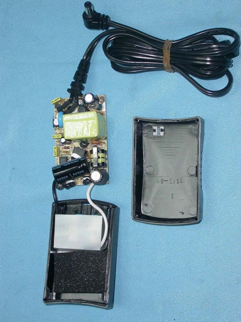
PKW-BEFW11S4V4
May 21, 2003Wireless Access Point Router
Equipment Class
DTS - Digital Transmission System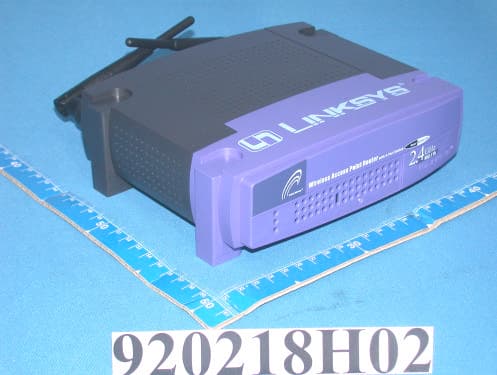
PKW-BEFW11S4V32
Apr 13, 2003Wireless Access Point Router with 4-Port Switch
Equipment Class
DTS - Digital Transmission System
PKW-WSB24-2
Apr 03, 2003Wireless Signal Booster
Equipment Class
DTS - Digital Transmission System
PKW-BEFCMUH4
Apr 01, 2003Cable Gateway
Equipment Class
DTS - Digital Transmission System