PKW-WAP51ABDual-Band Wireless Access Point
Cisco-Linksys, LLC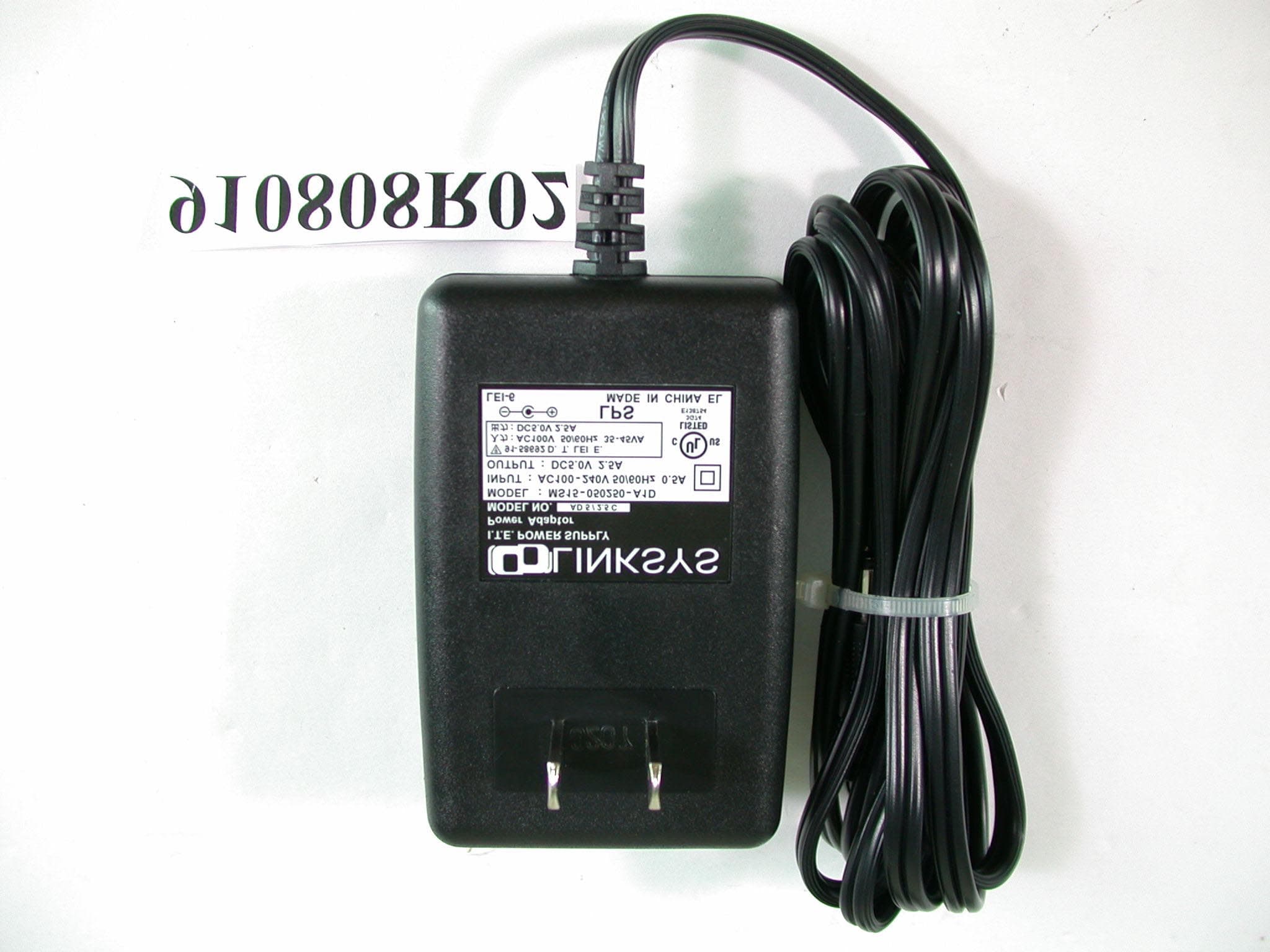
Click to zoom
Application Details
- Equipment Class
- NII - Unlicensed National Information Infrastructure TX
- Date of Grant
- Sep 14, 2002
- Application Purpose
- Original Equipment
- Date of Application
- Sep 14, 2002
- Equipment Note
- Dual-Band Wireless Access Point
- Frequency Range
- 5180.00000000 - 5320.00000000
- Company
- Cisco-Linksys, LLC
- Country
- United States
Documents & Files
Document Text
Text extracted from the exhibit documents filed with the FCC. Open a document above to read the original.
Users Manual
Instant Wireless TM Series Dual-Band Wireless Access Point Use this guide to install: WAP51AB User Guide COPYRIGHT & TRADEMARKS Copyright © 2002 Linksys, All Rights Reserved. Linksys is a registered trademark ofLinksys. Instant Wireless is a trademark of Linksys. Microsoft, Windows, and theWindows logo are registered trademarks of Microsoft Corporation. All other trademarksand brand names are the property of their respective proprietors. LIMITED WARRANTY Linksys guarantees that every Instant Wir eless™ Dual-Band Wir eless Access Point is free from physical defects in material and workmanship under normal use for one year fromthe date of purchase. If the product proves defective during this warranty period, callLinksys Technical Support in order to obtain a Return Authorization Number. BE SURETO HAVE YOUR PROOF OF PURCHASE AND A BARCODE FROM THE PRODUCT’SPACKAGING ON HAND WHEN CALLING. RETURN REQUESTS CANNOT BEPROCESSED WITHOUT PROOF OF PURCHASE. When returning a product, mark theReturn Authorization Number clearly on the outside of the package and include a copyof your original proof of purchase. All customers located outside of the United States ofAmerica and Canada shall be held responsible for shipping and handling charges.IN NO EVENT SHALL LINKSYS’ LIABILITY EXCEED THE PRICE PAID FOR THE PROD-UCT FROM DIRECT, INDIRECT, SPECIAL, INCIDENTAL, OR CONSEQUENTIAL DAM-AGES RESULTING FROM THE USE OF THE PRODUCT, ITS ACCOMPANYING SOFT-WARE, OR ITS DOCUMENTATION. LINKSYS DOES NOT OFFER REFUNDS FOR ANYPRODUCT. Linksys makes no warranty or representation, expressed, implied, or statuto-ry, with respect to its products or the contents or use of this documentation and allaccompanying software, and specifically disclaims its quality, performance, mer-chantability, or fitness for any particular purpose. Linksys reserves the right to revise orupdate its products, software, or documentation without obligation to notify any individ-ual or entity. Please direct all inquiries to:Linksys P.O. Box 18558, Irvine, CA 92623. FCC STATEMENTThis product has been tested and complies with the specifications for a Class B digitaldevice, pursuant to Part 15 of the FCC Rules. These limits are designed to provide rea-sonable protection against harmful interference in a residential installation. This equip-ment generates, uses, and can radiate radio frequency energy and, if not installed andused according to the instructions, may cause harmful interference to radio communi-cations. However, there is no guarantee that interference will not occur in a particularinstallation. If this equipment does cause harmful interference to radio or televisionreception, which is found by turning the equipment off and on, the user is encouraged totry to correct the interference by one or more of the following measures:• Reorient or relocate the receiving antenna• Increase the separation between the equipment or devices• Connect the equipment to an outlet other than the receiver’s• Consult a dealer or an experienced radio/TV technician for assistanceFCC Radiation Exposure StatementThis equipment complies with FCC radiation exposure limits set forth for an uncontrolledenvironment. This equipment should be installed and operated with minimum distance20cm between the radiator and your body. UG-WAP51AB-073102NC KL Dual-Band Wir eless Access Point Chapter 1: IntroductionThe Instant Wireless TM Dual-Band Wireless Access Point Install an access point that protects your infrastructure investment without lim-iting you to a single type of wireless technology. The Instant Wireless™ Dual-Band Wireless Access Point works simultaneously with both 802.11a and802.11b wireless standards to bring you the ultimate in wireless freedom. Thismeans you can enjoy the broadest spectrum of wireless networking now with-out the worry of a costly upgrade later.The Dual-Band Wireless Access Point's antennas enhance reception and pro-vide seamless roaming through your wireless networks. An advanced userauthentication feature and security encryption of up to 152 bits give you thehighest level of network security. It's both easy to install and easy to use. WithInternet browser-based configuration and Windows-Based Setup Wizard,you're always in control.Compact, lightweight, and power-efficient, the Dual-Band Wireless AccessPoint is the perfect wireless networking solution, no matter which wireless net-working standard you choose to use.• High Speed Wireless Networking • Protection for Your Wireless Investment - Supports Both 2.4GHz and 5GHzWireless Technology • Wireless Security with WEP Encryption of up to 152-bits and MACAddress Filtering • Quick and Easy to Use with Web-Based Management and Windows-BasedSetup Wizard • Operates in Both the 5GHz and 2.4GHz Bands • Wi-Fi Compatibility with 802.11a and 802.11b Technology • Supports up to 64 Simultaneous Wireless Users • Free Technical Support - 24 Hours a Day, 7 Days a Week, Toll-Free U.S.Calls • 1-Year Limited Warranty Table of ContentsChapter 1: Introduction 1 The Instant Wireless TM Dual-Band Wireless Access Point 1 Features 1 Package Contents 2 System Requirements 2 Chapter 2: Planning Your Wireless Network 3 Network Topology 3 Roaming 3 Chapter 3: Getting to Know the Dual-Band Wireless Access Point 4 The Dual-Band Wireless Access Point’s Back Panel 4 The Dual-Band Wireless Access Point’s Front Panel 5 Chapter 4: Connecting the Dual-Band Wireless Access Point 6 Chapter 5: Setting Up the Dual-Band Wireless Access Point 7 Chapter 6: Configuring the Dual-Band Wireless Access Point 16 The Setup Tab 16 The Password Tab 20 The Status Tab 21 The Help Tab 22 The Filter Tab 23 The Wireless Tab 24 Appendix A: Troubleshooting 27 Frequently Asked Questions 27 Appendix B: Setting Up the TCP/IP and IPX Protocols 32 Setting Up TCP/IP in Windows 32 TCP/IP Setup for Windows 95, 98, and Millennium 33 IPX Setup for Windows 95, 98, and Millennium 33 TCP/IP Setup for Windows NT 4.0 34 IPX Setup for Windows NT 4.0 34 TCP/IP Setup for Windo…
Text truncated - open the document above for the full version.
Cover Letter(s)
American Telecommunications Certification Body Inc. 6731 Whittier Ave, McLean, VA 22101 September 15, 2002 RE: PKW-WAP51AB FCC ID: THE LINKSYS GROUP, INC. After a review of the submitted information, I have a few comments on the above referenced Application. 1) Data sheet information found on Linksys Group’s web site quotes a power of +18 dBm (63 mW) – see data sheet provided separately. The users manual also state + 18 dBm (802.11a) and 15 dBm (802.11b). However the highest power quoted in the application is 14.6 dBm (29 mW) for 802.11and 10.5 dBm (11.3 mW). These are lower than expected for most access points and are 3-5 dB below the information given in the users manual and data sheet. Please comment. 2) Schematics were not provided for either the 802.11a or 802.11b mini-PCI RF boards. Please provide schematics for these boards. 3) Please provide information regarding each of the mini-PCI RF boards that are in this device (i.e., model, manufacturer, etc.). 4) For compliance testing of the radio, this device was tested as a stand-alone unit. However for DoC emissions it should be configured as part of a minimum configuration as specified by ANSI C63.4. Please confirm that the EUT has been properly configured as part of a fully configured for its DoC authorization. 5) FYI, Pages 5 and 10 of the test report references TIA/EIT-603-A. This standard is not necessary to show compliance for this device. 6) This device contains 2 transmitters which may be assumed to be transmitting simultaneously. Therefore this device must show that it meets co-location requirements (according to multiple frequency exposure criteria, the ratio of field strength or power density to the applicable exposue limit at the exposure location should be determined for each transmitter and the sum of these ratios must not exceed 1.0 for the location to be compliant. Please add this information to your RF exposure exhibit. 7) The users manual should also include co-location information to the user. 802.11A Questions 8) This device was tested for the data rate that produced the highest output power for normal mode (6 Mbps). What about “Turbo Mode” (usually highest power at 12 Mbps)? 9) Some devices in “Turbo Mode” use different channel lists. Please comment on if the “Turbo Mode” utilizes a different channel set. 10) Please provide power measurements for the “Turbo Mode”. 11) For the peak excursion measurement, please provide information regarding the RBW & VBW used for both traces. The information is only shown for one trace. 12) Please provide information in the users manual regarding 15.407(e). This information should be placed in the users manual (i.e. regarding the installation of the device - Chapter 4) in a location that is obvious to the reader. --- Continued on Next Page --- z Page 2November 16, 2002 13) In Section 5.6 of the test report it is not obvious how the levels were calculated using the substitution method. Please provide an example providing specific information regarding the substitution antenna (gain, etc) that show the calculations are for EIRP. Timothy R. Johnson Examining Engineer mailto: [email protected] The items indicated above must be submitted before processing can continue on the above referenced application. Failure to provide the requested information may result in application termination. Correspondence should be considered part of the permanent submission and may be viewed from the Internet after a Grant of Equipment Authorization is issued. Please do not respond to this correspondence using the email reply button. In order for your response to be processed expeditiously, you must submit your documents through the AmericanTCB.com website. Also, please note that partial responses increase processing time and should not be submitted. Any questions about the content of this correspondence should be directed to the sender.
Cover Letter(s)
American Telecommunications Certification Body Inc. 6731 Whittier Ave, McLean, VA 22101 October 13, 2002 RE: PKW-WAP51AB FCC ID: THE LINKSYS GROUP, INC. After a review of the submitted information, I have a few comments on the above referenced Application. 1) The Linksys website information and user manual discusses that this device states that this device may operate in a Turbo Mode up to 72 Mbps (reference previous questions 8, 9, & 10). However your last response stated that the device does not operate in Turbo Mode. Please comment. 2) The Users Manual still does not include the RF exposure information: "This device must not be co-located or operating in conjunction with any other antenna or transmitter other than those contained within this device." This information is required regardless of whether the two devices internally may function at the same time or not. Please provide an updated manual. 3) According to information on Linksys Website and within the users manual, this device operates simultaneously on both 802.11a & 802.11b (reference previous questions 6). In order to functionally perform well in a multi-user environment for both bands, we would also expect it to transmit in both bands simultaneously. However, this is not consistent with the information provided. Please explain. Please note that in performing the review we calculated that the device meets the RF exposure limits assuming both transmit simultaneously. Please explain and/or provide an updated RF exposure exhibit. 4) The information supplied in answer to previous question 13 is not clear. Please provide measured values and correction factors in a sample calculation. Usually this would be something like: Raw Reading dBm Cable Loss Antenna Gain of TX antenna at Signal Gen. -44 dBm - 5.0 dB + 6 dBi = -43 dBm Timothy R. Johnson Examining Engineer mailto: [email protected] The items indicated above must be submitted before processing can continue on the above referenced application. Failure to provide the requested information may result in application termination. Correspondence should be considered part of the permanent submission and may be viewed from the Internet after a Grant of Equipment Authorization is issued. Please do not respond to this correspondence using the email reply button. In order for your response to be processed expeditiously, you must submit your documents through the AmericanTCB.com website. Also, please note that partial responses increase processing time and should not be submitted. Any questions about the content of this correspondence should be directed to the sender.
Cover Letter(s)
Dear Tim, For Item 1), Revised users manual has been submitted to your folder. questions 2 & 3 have been answered Item 4), Yes, this device was tested under fullly configured. Item 5), refer to test report page 5 & 10, item 6),both transmitters will not be operated simultaneously by the software control. item 7), no need to consider the co-location problem as they will not be operated simultaneously. item 8,9,10) Turbo mode is not available in this device. item 11), refer to test report page 81, item 12), refer to the revised manual page 6, item 13), refer to test report page 97-100. Revised test reports and user manual were uploaded! Thanks, Regards, Vivi To: "Timothy R. Johnson" <[email protected]> Subject: =?big5?B?pl6rSKFHIFVSR0VOVCwgT1VUU1RBTkRJTkcgSVNTVUVTLi4uLi4u?= =?us-ascii?Q?---=3E_Linksys?= Group, FCC ID: PKW-WAP51AB In Printed for "Timothy R. Johnson" <[email protected]>
Cover Letter(s)
Dear Tim, For (1) and (3), I can only tell you that the information I have is given by our customer and also from the testing sample we have. I will ask our customer to revise the information on their web site For (2), I think Vivi has update the users manual. For (4), is there any rule part asking us to list the detail ?? We have done a lot of EIRP testing in Europe standard. We all use the same procedures. Do you think it is a mandatory to list all the detail ??? Best Regards, Dr. Alan Lane Manager, Advance Data Technology Tel: +886 3 3270910 Fax: +886 3 3270892 To: "Timothy R. Johnson" <[email protected]> Cc: [email protected], [email protected] Subject: =?big5?B? pl6rSKFHIFJlOiBVUkdFTlQsIE9VVFNUQU5ESU5HIElTU1VFUy4uLi4uLg==?= =?us-ascii?Q?---=3E_Linksys?= Group, FCC ID: PKW-WAP51AB Page 1 of 1In Printed for "Timothy R. Johnson" <[email protected]>
External Photos
Page 1 ANNEX PHOTOGRAPHS OF EUT Page 2 Page 3 Page 12
Internal Photos
Page 4 Page 5 Page 6 Page 7
Internal Photos
Page 8 Page 9 Page 10 Page 11
Operational Description
No. 1 Jen Ai Road, Hsinchu Industrial Park Hukou, Hsinchu, Taiwan 303 Web Site: www.gemtek.com.tw Phone: +886-3-598-5535 E-Mail: [email protected] Fax: +886-3-598-5585 WL-352B Wireless LAN Card Specifications Rev.1.0 Product Name 11 Mbps Wireless LAN Mini-PCI Card Model Number WL-352B Host Interface Mini-PCI Type III A Dimensions 59.7 x 59.95 x 3.5 mm Weight 11g Frequency Band 2.412 ~ 2.4835GHz (subject to local regulations) USA and Canada – 11 Most European countries – 13 Number of Channels France – 4 Japan – 14 Operating Voltage3.3V Current ConsumptionRX ≦ 230mA TX ≦ 350mA Modulation TypeDSSS (Direct Sequence Spread Spectrum) Data Rate11 Mbps; 5.5 Mbps; 2 Mbps; 1 Mbps Transmit PowerTyp. 14 dBm Receive SensitivityTpy –80 dBm @11Mbps Modulation11 Mbps and 5.5 Mbps: CCK; 2 Mbps: DQPSK; 1 Mbps: DBPSK Security64-bit, 128-bit WEP AntennaBuild-in Inside host LED indicatorNone Supplied DriverWindows 2000,WindowsXP StandardsIEEE 802.11b, Wi-Fi compliant Media Access ProtocolCSMA/CA with ACK Warranty1 year Temperature Range0 ~ 65°C (Operating), -20~85°C (Storage) HumidityMax. 95% Non-condensing Operating Range Open space: 100 – 300m; Indoor: 30m – 100m The transmission speed varies in the surrounding environment. RoamingFull mobility and seamless roaming from cell to cell and across access points Network ProtocolTCP/IP, IPX, NetBEUI Management UtilityLink configuration for network join and diagnostics EMC certification FCC part 15B, 15C ; R&TTE ; TELEC/JATE PackagingCustomer define CISCustomer define GemTek Technology #1 Jen Ai Road, Hsinchu Industrial Park Hukou, Hsinchu, Taiwan 303 Web Site: www.gemtek.com.twPhone: +886-3-598-5535 E-Mail: [email protected]: +886-3-598-5585 Detail Specifications are subject to change without further notification. Copyright © GemTek Technology November, 2001 WL-550 IEEE 802.11a Mini-PCI General Specification Sheet Revision History RevisionDateChange Description V0.12001/11/12Preliminary V0.22002/01/30Correct and update some spec. Specification Product Name54 Mbps Wireless LAN Mini-PCI Card Model NumberWL-550 Host Interface Mini PCI type III A Dimensions 60.0 x 50.90 x 5 mm Weight13g Frequency BandUnlicensed National Information Infrastructure (U-NII) frequency band, 5.15GHz to 5.35GHz (subject to local regulations) Number of Channel 5.15〜5.25GHz (lower band) Four 20MHz Channels 5.25〜5.35GHz(middle band) Four 20MHz Channels Operating Voltage3.3V ± 5% 5V ± 5% for external PA SpreadingOrthogonal Frequency Division Multiplexing (OFDM) Modulation64 QAM, 16 QAM, QPSK, BPSK Data Rate54, 48, 36,24,18,12, 9, 6 Mbps per channel, auto fallback for extended range; (option : Enhanced proprietary Turbo Mode up to 72 Mbps) Security64/128/152-bit WEP Encryption Antenna Build-in inside host.(HRS:U.FL-R-SMT(10)) Transmitted powerMax. +17dBm @ 16QAM R3/4 Receive Sensitivity Nominal Temp Range: - 6Mbps10-5 BER @ -86dBm, typical - 9Mbps10-5 BER @ -85dBm, typical - 12Mbps10-5 BER @ -84dBm, typical - 18Mbps 10-5 BER @ -82dBm, typical - 24Mbps10-5 BER @ -80dBm, typical - 36Mbps10-5 BER @ -75dBm, typical - 48Mbps10-5 BER @ -68dBm, typical - 54Mbps 10-5 BER @ -67dBm, typical Power consumptionMax.1.95W Supplied DriverWindows 98SE/ME/NT4.0/2000/XP StandardsIEEE 802.3, IEEE 802.3u, IEEE 802.11a Warranty1 year Temperature Range0 ~ 60°C (Operating); -40 ~ 85°C (Storing) HumidityMax. 95% non-condensing Operating RangeOpen Space: Up to 300 m: Indoor: 100 m The transmission speed varies in the surrounding environment RoamingSeamless roaming among 802.11a compliant access points Network ProtocolTCP/IP, IPX, NDIS4, and NDIS5 ,NDIS 5.1 GemTek Technology - Wireless LAN 2 of 3Draft 1.0 June 8, 1999 Management UtilityConfiguration Utility for network join and diagnostics EMC certificationFCC part 15 class in US, and TELEC/JATE in Japan System RequirementsLaptop PC containing ! 64MB memory or greater ! 300MHz processor or greater Microsoft Windows 98 Second Edition/Millennium Edition/2000/NT 4.0 with Service Pack 6
Operational Description
FCC ID: PKW-WAP51AB ADT No.910808R02 Technical Description The transmitter of the EUT is powered by power adapter and connected with notebook through RJ45 port. The antenna is Dipole antenna. There is no antenna connector. Under normal use condition, the user has to keep at least 20cm separation distance between radiator and the body of the user. This device is a Dual-Band Wireless Access Point which operates in both the 5GHz and 2.4GHz bands, the maximum data rate could be 72Mbps. For more detailed instruction, please take a look at the user’s manual. FCC 15.407(c) states : The device shall automatically discontinue transmission in case of either absence of information to transmit or operational failure. These provisions are not intended to preclude the transmission of control or signaling information or the use of repetitive codes used by certain digital technologies to complete frame or burst intervals. Applicants shall include in their application for equipment authorization a description of hoe this requirement is met” Data transmission is always initiated by software, which is then pass down through the MAC, through the digital and analog baseband, and finally to the RF chip. Several special packets (ACKs, CTS, PSPoll, etc...) are initiated by the MAC. There are the only ways the digital baseband portion will turn on the RF transmitter, which it then turns off at the end of the packet. Therefore, the transmitter will be on only while one of the aforementioned packets are being transmitted.
RF Exposure Info
ADT No: 910808R02 1 FCC TEST REPORT REPORT NO.: RF910808R02 MODEL NO.: WAP51AB ACCORDING: FCC Guidelines for Human Exposure IEEE C95.1 APPLICANT:The Linksys Group, Inc. ADDRESS:17401 Armstrong Ave., Irvine, CA 92614 ISSUED BY:Advance Data Technology Corporation LAB LOCATION:47 14th Lin, Chiapau Tsun, Linko, Taipei, Taiwan, R.O.C. 0528 ILAC MRA Lab Code: 200102-0 ADT No: 910808R02 2 RF Exposure Measurement 1. Introduction In this document, we try to prove the safety of radiation harmfulness to the human body for our product. The limit for Maximum Permissible Exposure (MPE) specified in FCC 1.1310 is followed. The Gain of the antenna used in this product is measured in a Fully Anechoic Chamber (FAC) calibrated for antenna measurement in ADT, and also the maximum total power input to the antenna is measured. Through the Friis transmission formula and the maximum gain of the antenna, we can calculate the distance, away from the product, where the limit of MPE is reached. Although the Friis transmission formula is a far field assumption, the calculated result of that is an over-prediction for near field power density. We will take that as the worst case to specify the safety range. 2. RF Exposure Limit According to FCC 1.1310: The criteria listed in the following table shall be used to evaluate the environmental impact of human exposure to radio-frequency (RF) radiation as specified in 1.1307(b) LIMITS FOR MAXIMUM PERMISSIBLE EXPOSURE (MPE) Frequency Range (MHz) Electric Field Strength (V/m) Magnetic Field Strength (A/m) Power Density (mW/cm 2 ) Average Time (minutes) (A)Limits For Occupational / Control Exposures 300-1500......F/3006 1500-100,000......56 (B)Limits For General Population / Uncontrolled Exposure 300-1500......F/15006 1500-100,000......1.030 F = Frequency in MHz ADT No: 910808R02 3 3. Friis Formula Friis transmission formula : Pd = (Pout*G) / (4*pi*r 2 ) where Pd = power density in mW/cm 2 Pout = output power to antenna in mW G = gain of antenna in linear scale Pi = 3.1416 R = distance between observation point and center of the radiator in cm Pd is the limit of MPE, 1 mW/cm 2 . If we know the maximum Gain of the antenna and the total power input to the antenna, through the calculation, we will know the distance r where the MPE limit is reached. Ref. : David K. Cheng, Field and Wave Electromagnetics, Second Edition, Page 640, Eq. (11-133). 4 EUT Operating condition The software provided by Manufacturer enabled the EUT to transmit and receive data at lowest, middle and highest channel individually. 5 Climate Condition The temperature and related humidity: 20 deg. C and 63 % RH 6. Classification This device is not fixed inside the host equipment, it is connected with host through wire. So it is easy to be re-located in the place where at least 20 cm far away from the body of the user. Warning statement to the user for keeping at least 20cm or more separation distance with the antenna should be included in users manual. So, this device is classified as Mobile Device. ADT No: 910808R02 4 7 Test Results 7.1 Antenna Gain The maximum Gain measured in Fully Anechoic Chamber is 1dBi or 1.26(numeric). 7.2 Output Power Into Antenna & RF Exposure Distance : For Part 802.11b: CHANNEL CHANNEL FREQUENCY (MHz) OUTPUT POWER TO ANTENNA (mW) MINIMUM ALLOWABLE DISTANCE ( r ) FROM SKIN (Centi-Meter) 1241211.301.06 624379.750.99 1124629.040.95 For Part 802.11a: CHANNEL CHANNEL FREQUENCY (MHz) OUTPUT POWER TO ANTENNA (mW) MINIMUM ALLOWABLE DISTANCE ( r ) FROM SKIN (Centi-Meter) 151806.000.78 4524015.701.25 5526029.041.71 853205.750.76 The minimum allowable distance is very close to the enclosure of the antenna. So, the user has no need to worry about the harmfulness of radiation. But it is recommended to always keep, at least, 20 cm separation distance with the antenna.
Test Report
FCC ID: PKW-WAP51AB Report No.: RF910808R02 1 Issued: Sep. 12, 2002 FCC TEST REPORT REPORT NO.: RF910808R02 MODEL NO.: WAP51AB RECEIVED: July 29, 2002 TESTED: July 30 ~ Sep. 9, 2002 APPLICANT:The Linksys Group, Inc. ADDRESS:17401 Armstrong Ave., Irvine, CA 92614 ISSUED BY:Advance Data Technology Corporation LAB LOCATION:47 14 th Lin, Chiapau Tsun, Linko, Taipei, Taiwan, R.O.C. This test report consists of 112 pages in total. It may be duplicated completely for legal use with the approval of the applicant. It should not be reproduced except in full, without the written approval of our laboratory. The client should not use it to claim product endorsement by CNLA, NVLAP or any government agencies. The test results in the report only apply to the tested sample. 0528 ILAC MRA Lab Code: 200102-0 FCC ID: PKW-WAP51AB Report No.: RF910808R02 2 Issued: Sep. 12, 2002 Table of Contents 1CERTIFICATION .................................................................................................................... 5 2SUMMARY OF TEST RESULTS............................................................................................ 6 3GENERAL INFORMATION .................................................................................................... 8 3.1GENERAL DESCRIPTION OF EUT ...................................................................................... 8 3.2DESCRIPTION OF TEST MODES ........................................................................................ 9 3.3GENERAL DESCRIPTION OF APPLIED STANDARDS ..................................................... 10 3.4DESCRIPTION OF SUPPORT UNITS................................................................................. 10 4TEST TYPES AND RESULTS (FOR PART 802.11b) .......................................................... 11 4.1CONDUCTED EMISSION MEASUREMENT....................................................................... 11 4.1.1LIMITS OF CONDUCTED EMISSION MEASUREMENT .................................................... 11 4.1.2TEST INSTRUMENTS ......................................................................................................... 11 4.1.3TEST PROCEDURES .......................................................................................................... 12 4.1.4DEVIATION FROM TEST STANDARD ................................................................................ 12 4.1.5TEST SETUP ....................................................................................................................... 13 4.1.6EUT OPERATING CONDITIONS......................................................................................... 13 4.1.7TEST RESULTS ................................................................................................................... 14 4.2RADIATED EMISSION MEASUREMENT ............................................................................ 20 4.2.1LIMITS OF RADIATED EMISSION MEASUREMENT ......................................................... 20 4.2.2TEST INSTRUMENTS ......................................................................................................... 21 4.2.3TEST PROCEDURES .......................................................................................................... 22 4.2.4DEVIATION FROM TEST STANDARD ................................................................................ 22 4.2.5TEST SETUP ....................................................................................................................... 23 4.2.6EUT OPERATING CONDITIONS......................................................................................... 23 4.2.7TEST RESULTS ................................................................................................................... 24 4.36dB BANDWIDTH MEASUREMENT ................................................................................... 29 4.3.1LIMITS OF 6dB BANDWIDTH MEASUREMENT ................................................................ 29 4.3.2TEST INSTRUMENTS ......................................................................................................... 29 4.3.3TEST PROCEDURE ............................................................................................................30 4.3.4DEVIATION FROM TEST STANDARD ................................................................................ 30 4.3.5TEST SETUP ....................................................................................................................... 30 4.3.6EUT OPERATING CONDITIONS......................................................................................... 30 4.3.7TEST RESULTS ................................................................................................................... 31 4.4MAXIMUM PEAK OUTPUT POWER ................................................................................... 35 4.4.1LIMITS OF MAXIMUM PEAK OUTPUT POWER MEASUREMENT ................................... 35 4.4.2INSTRUMENTS.................................................................................................................... 35 4.4.3TEST PROCEDURES .......................................................................................................... 36 4.4.4DEVIATION FROM TEST STANDARD ................................................................................ 36 4.4.5TEST SETUP ....................................................................................................................... 36 4.4.6EUT OPERATING CONDITIONS......................................................................................... 36 4.4.7TEST RESULTS ................................................................................................................... 37 4.5POWER SPECTRAL DENSITY MEASUREMENT .............................................................. 38 FCC ID: PKW-WAP51AB Report No.: RF910808R02 3 Issued: Sep. 12, 2002 4.5.1LIMITS OF POWER SPE…
Text truncated - open the document above for the full version.
Test Report
FCC ID: PKW-WAP51AB Report No.: RF910808R02 81 Issued: Sep. 12, 2002 5.4.3 TEST PROCEDURE 1. The transmitter output was connected to the spectrum analyzer. 2. Set the spectrum bandwidth span to view the entire spectrum. 3. Using peak detector and Max-hold func…
Text truncated - open the document above for the full version.
Contact Information
Applicant
Ms Jennifer Yu(Associate Engineer)
Technical Contact
Advance Data Technology CorporationAlan Lane
[email protected]+886-3-327-0910
13-1, Lane19, WenShan 3rd., St. · Taoyuan · Taiwan
Non-Technical Contact
Advance Data Technology CorporationAlan Lane
[email protected]+886-3-327-0910
Test Firm
Bureau Veritas CPS (H.K.) Ltd. Taoyuan BranchTommy Wu
Technical Specifications
| # | Rule Parts | Frequency Range | Power Output | Tolerance |
|---|---|---|---|---|
| 1 | 15E | 5.18 GHz - 5.32 GHz | 29.00 mW | 0.0200000000 % |
Other Applications from Cisco-Linksys, LLC

PKW-WMP54GV2
May 29, 2003Wireless-G PCI Adapter
Equipment Class
DTS - Digital Transmission System
PKW-BEFW11S4V4
May 21, 2003Wireless Access Point Router
Equipment Class
DTS - Digital Transmission System
PKW-BEFW11S4V32
Apr 13, 2003Wireless Access Point Router with 4-Port Switch
Equipment Class
DTS - Digital Transmission System
PKW-WSB24-2
Apr 03, 2003Wireless Signal Booster
Equipment Class
DTS - Digital Transmission System
PKW-BEFCMUH4
Apr 01, 2003Cable Gateway
Equipment Class
DTS - Digital Transmission System