PKW-WMP11-V27Instant Wireless PCI Card
Cisco-Linksys, LLC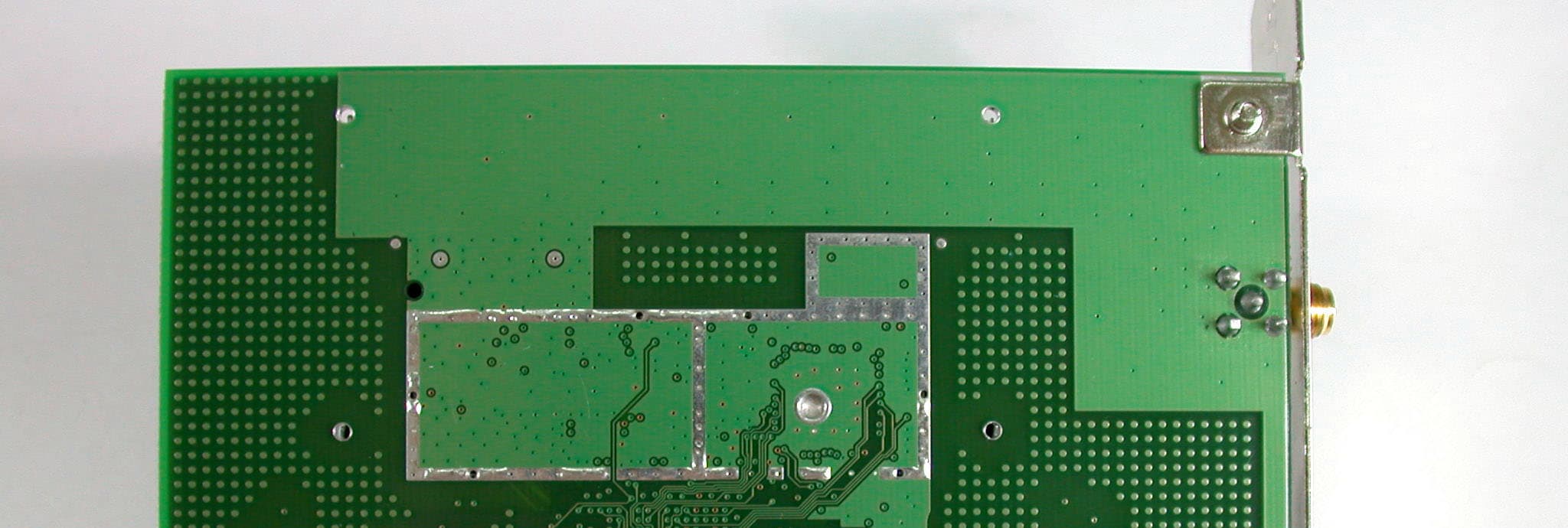
Click to zoom
Application Details
- Equipment Class
- DSS - Part 15 Spread Spectrum Transmitter
- Date of Grant
- Aug 06, 2002
- Application Purpose
- Original Equipment
- Date of Application
- Aug 06, 2002
- Equipment Note
- Instant Wireless PCI Card
- Frequency Range
- 2412.00000000 - 2462.00000000
- Company
- Cisco-Linksys, LLC
- Country
- United States
Documents & Files
Document Text
Text extracted from the exhibit documents filed with the FCC. Open a document above to read the original.
Users Manual
Instant Wireless TM Series Wireless PCI Card User Guide Use this Guide to install the following:WMP11 COPYRIGHT & TRADEMARKS Copyright © 2001 Linksys, All Rights Reserved. Instant Wir eless™ is a r egistered trade- mark of Linksys. Microsoft, Windows, and the Windows logo are registered trademarksof Microsoft Corporation. All other trademarks and brand names are the property of theirrespective proprietors. LIMITED WARRANTY Linksys guarantees that every Instant Wir eless™ Wir eless PCI Card is free from physical defects in material and workmanship for one year from the date of purchase, when usedwithin the limits set forth in the Specification section of this User Guide. If these productsprove defective during this warranty period, call Linksys Customer Support in order toobtain a Return Authorization Number. BE SURE TO HAVE YOUR PROOF OF PUR-CHASE AND A BARCODE FROM THE PRODUCT'S PACKAGING ON HAND WHENCALLING. RETURN REQUESTS CANNOT BE PROCESSED WITHOUT PROOF OF PUR-CHASE. When returning a product, mark the Return Authorization Number clearly on theoutside of the package and include your original proof of purchase. All customers locat-ed outside of the United States of America and Canada shall be held responsible forshipping and handling charges.IN NO EVENT SHALL LINKSYS’ LIABILITY EXCEED THE PRICE PAID FOR THE PROD-UCT FROM DIRECT, INDIRECT, SPECIAL, INCIDENTAL, OR CONSEQUENTIAL DAM-AGES RESULTING FROM THE USE OF THE PRODUCT, ITS ACCOMPANYING SOFT-WARE, OR ITS DOCUMENTATION. LINKSYS DOES NOT OFFER REFUNDS FOR ANYPRODUCT. Linksys makes no warranty or representation, expressed, implied, or statuto-ry, with respect to its products or the contents or use of this documentation and allaccompanying software, and specifically disclaims its quality, performance, mer-chantability, or fitness for any particular purpose. Linksys reserves the right to revise orupdate its products, software, or documentation without obligation to notify any individ-ual or entity. Please direct all inquiries to:Linksys P.O. Box 18558, Irvine, CA 92623. FCC STATEMENTThis product have been tested and complies with the specifications for a Class B digitaldevice, pursuant to Part 15 of the FCC Rules. These limits are designed to provide rea-sonable protection against harmful interference in a residential installation. This equip-ment generates, uses, and can radiate radio frequency energy and, if not installed andused according to the instructions, may cause harmful interference to radio communi-cations. However, there is no guarantee that interference will not occur in a particularinstallation. If this equipment does cause harmful interference to radio or televisionreception, which is found by turning the equipment off and on, the user is encouraged totry to correct the interference by one or more of the following measures:• Reorient or relocate the receiving antenna• Increase the separation between the equipment or device• Connect the equipment to an outlet other than the receiver’s• Consult a dealer or an experienced radio/TV technician for assistance IntroductionPut the “mobile” back into mobile computing! Whether you’re at your desk orin the boardroom, the Linksys Instant Wireless™ Wireless PCI Card allows youto share printers, files, and other resources anywhere within your LAN infra-structure, increasing your productivity and keeping you “in touch.” The Instant Wireless™ Wireless PCI Card now has a high-powered antennathat provides greater ranges than ever. Error correction in the chipset keeps youoperating at higher transmission rates for longer distances. Ready to run in PCs running Windows 95, 98, Millennium, NT, and 2000, theInstant Wireless™ Wireless PCI Card from Linksys is truly a “must-have” forall PC users.• 11 Mbps High-Speed Data Transfer Rate• Compatible with Virtually All Major Network Operating Systems• Plug-and-Play Operation Provides Easy Setup• Integrated Equalizer Recovers Weak Signals and Enhances Sensitivity• Sturdy Metal Design with Integrated Antenna• Works with All Standard Internet Applications• Interoperable with IEEE 802.11b (DSSS) 2.4GHz-Compliant Equipment• Clear Channel Assessment Increases Network Throughput• Hardware Buffer Chaining Provides High Performance While Reading and Writing Buffers • Capable of up to 128-Bit WEP• Free Technical Support—24 Hours a Day, 7 Days a Week for North America Only • 1-Year Limited Warranty 1 FeaturesThe Instant Wireless TM Wireless PCI Card Table of ContentsIntroduction 1 The Instant Wireless TM Wireless PCI Card 1 Features 1 Package Contents 2 System Requirements 2 Planning Your Wireless Network 3 Network Topology 3 Roaming 3 Installing the Drivers and Configuration Utility for Windows 95, 98, ME and 2000 4 Before You Start 4 Running the Auto Driver Installation 4 Ad-Hoc Versus Infrastructure Mode 8 Infrastructure Mode 9 Ad-Hoc Mode 11 Installing the Wireless PCI Card 14 Installing the Drivers and Configuration Utility for Windows NT 15 Overview 15 Installing the Drivers for Windows NT 15 Installing the Configuration Utility for Windows NT 29 Configuration Utility 30 Using the Configuration Utility 30 Installing Network Protocols 37 Troubleshooting 39 Common Problems and Solutions 39 Frequently Asked Questions 39 Glossary 43 Specifications 48 Environmental 48 Warranty Information 49 Contact Information 50 Instant Wireless TM Series Wireless PCI Card 3 2 Planning Your Wireless NetworkNetwork TopologyA wireless LAN is exactly like a regular LAN, except that each computer in theLAN uses an Instant Wireless™ Wireless PCI Card to connect to the networkusing no wires. Computers in a wireless LAN must be configured to share thesame radio channel.The Instant Wireless™ Wireless PCI Card provides LAN access for wirelessworkstations. An integrated wireless and wired LAN is called an Infrastructureconfiguration. A group of Wireless PCI Card users and an Access Point com-pose a Basic Service Set (BSS). Each PC equipped with an Wireless PCI Cardin a BSS can talk t…
Text truncated - open the document above for the full version.
Cover Letter(s)
Inform Letter Dear Customer, According to FCC’s regulation, the following Declaration of Conformity has to be made by a company located in USA. They are: This device has been confirmed to be in compliance with the requirements of ANSI C63.4 & FCC part 15 regulations. The test result has been shown in the ADT test report with number RF910705R01A. And this compliance is subject to the following two conditions: (1) This device may not cause harmful interference and, (2) This device must accept any interference received, including interference that may cause undesired operation. This declaration can be a separate sheet and be sure that the following message will be also included in this declaration: 1) Product name, model name and trade name. 2) Company name, and address of the one who is responsible for this declaration. 3) Name, title, telephone and fax number as well as the signature of the contact person. Thanks for your attention.
External Photos
Page 1 ANNEX PHOTOGRAPHS OF EUT Page 2 Page 3
ID Label/Location Info
³Ó³Ð-WMP11•900630³Ó³Ð-WMP11•900630³Ó³Ð-WMP11•900630³Ó³Ð-WMP11•900630 FCC ID: PKW-WMP11-V27FCC ID: PKW-WMP11
Internal Photos
Page 4 Page 5
Operational Description
FCC ID: PKW-WMP11-V27 ADT No.910705R02 Operational Description The transmitter of the EUT is powered by host equipment. The antenna is Dipole antenna. The antenna connector is Reversed SMA connector. Under normal use condition, the user has to keep at least 20cm separation distance between radiator and the body of the user. The other instruction, please have a look at the users manual. DSSS Information This device is Direct Sequence Spread Spectrum, the data is mixed by pseudorandom code which is an orthogonal code. The mixed data is digital modulated by BPSK and QPSK technique depends on the data rates. The CCK coding is applied for increasing the data rate, and also the processing gain will be increased. The bit rates are 1,2,5.5,11Mbps, the symbol rates are 1,1,1.375,1.375Mbps, the chip rates are always 11Mbps. So, the Chip/symbol is 11,11,8 and 8 respectively. Although is higher bit rate, the processing gain is lower than 10, but the CCK coding used in higher bit rate will provide 2.2dB coding gain.
RF Exposure Info
ADT No: 910705R02 1 FCC TEST REPORT REPORT NO.: RF910705R01A MODEL NO.: WMP11 ACCORDING: FCC Guidelines for Human Exposure IEEE C95.1 APPLICANT:The Linksys Group, INC. ADDRESS: 17401 Armstrong Ave. Irvine, CA 92614 ISSUED BY:Advance Data Technology Corporation LAB LOCATION:47 14th Lin, Chiapau Tsun, Linko, Taipei, Taiwan, R.O.C. 0528 ILAC MRA Lab Code: 200102-0 ADT No: 910705R02 2 RF Exposure Measurement 1. Introduction 2.4GHz frequency band is regarded specially as a dangerous band for its heating harmfulness to the human body. That’s why microwave oven is operating in this frequency band. The manufacturer whose product is working in this frequency band is obligatory to prove the harmfulness of his product. In this document, we try to prove the safety of radiation harmfulness to the human body for our product. The limit for Maximum Permissible Exposure (MPE) specified in FCC 1.1310 is followed. The Gain of the antenna used in this product is measured in a Fully Anechoic Chamber (FAC) calibrated for antenna measurement in ADT, and also the maximum total power input to the antenna is measured. Through the Friis transmission formula and the maximum gain of the antenna, we can calculate the distance, away from the product, where the limit of MPE is reached. Although the Friis transmission formula is a far field assumption, the calculated result of that is an over-prediction for near field power density. We will take that as the worst case to specify the safety range. 2. RF Exposure Limit According to FCC 1.1310: The criteria listed in the following table shall be used to evaluate the environmental impact of human exposure to radio-frequency (RF) radiation as specified in 1.1307(b) LIMITS FOR MAXIMUM PERMISSIBLE EXPOSURE (MPE) Frequency Range (MHz) Electric Field Strength (V/m) Magnetic Field Strength (A/m) Power Density (mW/cm 2 ) Average Time (minutes) (A)Limits For Occupational / Control Exposures 300-1500......F/3006 1500-100,000......56 (B)Limits For General Population / Uncontrolled Exposure 300-1500......F/15006 1500-100,000......1.030 F = Frequency in MHz ADT No: 910705R02 3 3. Friis Formula Friis transmission formula : Pd = (Pout*G) / (4*pi*r 2 ) where Pd = power density in mW/cm 2 Pout = output power to antenna in mW G = gain of antenna in linear scale Pi = 3.1416 R = distance between observation point and center of the radiator in cm Pd is the limit of MPE, 1 mW/cm 2 . If we know the maximum Gain of the antenna and the total power input to the antenna, through the calculation, we will know the distance r where the MPE limit is reached. Ref. : David K. Cheng, Field and Wave Electromagnetics, Second Edition, Page 640, Eq. (11-133). 4 EUT Operating condition The software provided by Manufacturer enabled the EUT to transmit and receive data at lowest, middle and highest channel individually. 5 Climate Condition The temperature and related humidity: 25 deg. C and 55 % RH 6. Classification This device is used to be fixed in the slot inside the desktop PC. 20cm separation can be maintained easily. Warning statement to the user for keeping at least 20cm or more separation distance with the antenna should be included in users manual. So, this device is classified as Mobile Device. ADT No: 910705R02 4 7 Test Results 7.1 Antenna Gain The maximum Gain measured in Fully Anechoic Chamber is 5dBi or 3.16 (numeric). 7.2 Output Power Into Antenna & RF Exposure Distance : CHANNEL CHANNEL FREQUENCY (MHz) OUTPUT POWER TO ANTENNA (mW) MINIMUM ALLOWABLE DISTANCE ( r ) FROM SKIN (Centi-Meter) 1241217.022.07 6243716.372.03 11246214.591.92 The minimum allowable distance is very close to the enclosure of the antenna. So, the user has no need to worry about the harmfulness of radiation. But it is recommended to always keep, at least, 20cm separation distance with the antenna.
Schematics
55 44 33 22 11 D D C C B B A A <Doc> XB MW300-BF C 11 Thursday, July 25, 2002 TitleSize Document Number Rev Date: Sheet of TDIO AD21 AD16 AD16AD18 AD18 AD22AD20 AD22AD20 AD6AD2 AD6AD2 AD30AD24AD28C/BE0#AD15AD11AD0AD4AD13STOP#AD9IDSELTRDY#PME#PARRST#GNT# GNT#RST#PME#PARIDSELTRDY#FRAME#AD4AD0AD13AD9AD15AD11C/BE0#STOP#AD28AD30AD24 FRAME# AD25 AD26 AD26 AD5AD1AD31AD27AD23AD29AD17SERR#C/BE1#C/BE2#C/BE3#AD19AD12AD10AD8AD7AD14AD3IRDY#DEVSEL#PERR#PCICLKREQ# AD5AD1AD25AD23AD27AD31AD29AD17SERR#C/BE1#C/BE3#AD19C/BE2#AD12AD7AD10AD8AD3AD14IRDY#PERR#PCICLKREQ# N134661 N134661 N135212 N135215 N134663 N134659 PVCC VCC PVCC VCC VCC VCC PVCC J4 GOLD124C 1234567891011 12 13 14 15 16 17 18 19 20 21 22 23 24 25 26 27 28 29 30 31 32 33 34 35 36 37 38 39 40 41 42 43 44 45 46 47 48 49 50 51 52 53 54 55 56 57 58 59 60 61 62 63 64 65 66 67 68 69 70 71 72 73 74 75 76 77 78 79 80 81 82 83 84 85 86 87 88 89 90 91 92 93 94 95 96 97 98 99 100 101 102 103 104 105 106 107 108 109 110 111 112 113 114 115 116 117 118 119 120 121 122 123 124 U208 2 3 1 4 IN OUT GND IN J1 12 P1 PCI1-6 A5A6A7A8A9A10A11A12A13A14A15A16A17A18A19A20A21A22A23A24A25A26A27A28A29A30A31A32A33A35A34A36A37A38A39A40A41A42A43A44A45A46A47A48A49A50A51A52A53A54A55A56A57A58 B5B6B7B8B9 B10B11B12B13B14B15B16B17B18B19B20B21B22B23B24B25B26B27B28B29B30B31B32B33B34B35B36B37B38B39B40B41B42B43B44B45B46B47B48B49B50B51B52B53B54B55B56B57B58 A1A2A3A4 B1B2B3B4 C213 0.1uF + C21810uF/16V + C21110uF/16V LED1 12 34 R215330 + C21210uF/16V C214 0.1uF R212 470 J9CON2 1 2 J7CON2 1 2 J6 1 + C21710uF/16V CON1 SMACONNA 12 3 4 5 C215 0.1uF C216 0.1uF
Test Report
FCC ID: PKW-WMP11-V27 Report No.: RF910705R01A1Issued: July 29, 2002 FCC TEST REPORT REPORT NO.: RF910705R01A MODEL NO.: WMP11 RECEIVED: July 05, 2002 TESTED: July 5 ~ July 25, 2002 APPLICANT: The Linksys Group, INC. ADDRESS: 17401 Armstrong Ave. Irvine, CA 92614 ISSUED BY: Advance Data Technology Corporation LAB LOCATION: 47 14th Lin, Chiapau Tsun, Linko, Taipei, Taiwan, R.O.C. This test report consists of 45 pages in total. It may be duplicated completely for legal use with the approval of the applicant. It should not be reproduced except in full, without the written approval of our laboratory. The client should not use it to claim product endorsement by CNLA, NVLAP or any government agencies. The test results in the report only apply to the tested sample. 0528 ILAC MRA Lab Code: 200102-0 FCC ID: PKW-WMP11-V27 Report No.: RF910705R01A2Issued: July 29, 2002 Table of Contents 1CERTIFICATION ......................................................................................................4 2SUMMARY OF TEST RESULTS ..............................................................................5 3GENERAL INFORMATION.......................................................................................6 3.1GENERAL DESCRIPTION OF EUT.........................................................................6 3.2DESCRIPTION OF TEST MODES...........................................................................7 3.3GENERAL DESCRIPTION OF APPLIED STANDARDS ..........................................7 3.4DESCRIPTION OF SUPPORT UNITS .....................................................................8 4TEST TYPES AND RESULTS ..................................................................................9 4.1CONDUCTED EMISSION MEASUREMENT ...........................................................9 4.1.1 LIMITS OF CONDUCTED EMISSION MEASUREMENT......................................... 9 4.1.2 TEST INSTRUMENTS.............................................................................................. 9 4.1.3 TEST PROCEDURES ............................................................................................ 10 4.1.4 TEST SETUP ......................................................................................................... 10 4.1.5 EUT OPERATING CONDITIONS ........................................................................... 11 4.1.6 TEST RESULTS ..................................................................................................... 12 4.2RADIATED EMISSION MEASUREMENT ..............................................................18 4.2.1 LIMITS OF RADIATED EMISSION MEASUREMENT............................................ 18 4.2.2 TEST INSTRUMENTS............................................................................................ 19 4.2.3 TEST PROCEDURES ............................................................................................ 20 4.2.4 TEST SETUP ......................................................................................................... 21 4.2.5 EUT OPERATING CONDITIONS ........................................................................... 21 4.2.6 TEST RESULTS ..................................................................................................... 22 4.36dB BANDWIDTH MEASUREMENT .....................................................................26 4.3.1 LIMITS OF 6dB BANDWIDTH MEASUREMENT ................................................... 26 4.3.2 TEST INSTRUMENTS............................................................................................ 26 4.3.3 TEST PROCEDURE............................................................................................... 27 4.3.4 TEST SETUP ......................................................................................................... 27 4.3.5 EUT OPERATING CONDITIONS ........................................................................... 27 4.3.6 TEST RESULTS ..................................................................................................... 28 4.4MAXIMUM PEAK OUTPUT POWER .....................................................................31 4.4.1 LIMITS OF MAXIMUM PEAK OUTPUT POWER MEASUREMENT...................... 31 4.4.2 INSTRUMENTS...................................................................................................... 31 4.4.3 TEST PROCEDURES ............................................................................................ 32 4.4.4 TEST SETUP ......................................................................................................... 32 4.4.5 EUT OPERATING CONDITIONS ........................................................................... 32 4.4.6 TEST RESULTS ..................................................................................................... 33 4.5POWER SPECTRAL DENSITY MEASUREMENT.................................................34 4.5.1 LIMITS OF POWER SPECTRAL DENSITY MEASUREMENT .............................. 34 4.5.2 TEST INSTRUMENTS............................................................................................ 34 4.5.3 TEST PROCEDURE............................................................................................... 35 4.5.4 TEST SETUP ......................................................................................................... 35 4.5.5 EUT OPERATING CONDITION ............................................................................. 35 4.5.6 TEST RESULTS ..................................................................................................... 36 4.6BAND EDGES MEASUREMENT ...........................................................................39 FCC ID: PKW-WMP11-V27 Report No.: RF910705R01A3Issued: July 29, 2002 4.6.1 LIMITS OF BAND EDGES MEASUREMENT ........................................................ 39 4.6.2 TEST INSTRUMENTS...........................................................…
Text truncated - open the document above for the full version.
Test Setup Photos
FCC ID: PKW-WMP11-V27 Report No.: RF910705R01A43Issued: July 29, 2002 5 PHOTOGRAPHS OF THE TEST CONFIGURATION CONDUCTED EMISSION TEST FCC ID: PKW-WMP11-V27 Report No.: RF910705R01A44Issued: July 29, 2002 RADIATED EMISSION TEST
Contact Information
Applicant
Ms Jennifer Yu(Associate Engineer)
Technical Contact
Advance Data Technology CorporationVivi Wang
[email protected]+886 3 327 0910
13-1, Lane 19, WenShan 3rd St · Taoyuan · Taiwan
Test Firm
Bureau Veritas CPS (H.K.) Ltd. Taoyuan BranchRichard Chen
Technical Specifications
| # | Rule Parts | Frequency Range | Power Output |
|---|---|---|---|
| 1 | 15C | 2.41 GHz - 2.46 GHz | 17.00 mW |
Other Applications from Cisco-Linksys, LLC

PKW-WMP54GV2
May 29, 2003Wireless-G PCI Adapter
Equipment Class
DTS - Digital Transmission System
PKW-BEFW11S4V4
May 21, 2003Wireless Access Point Router
Equipment Class
DTS - Digital Transmission System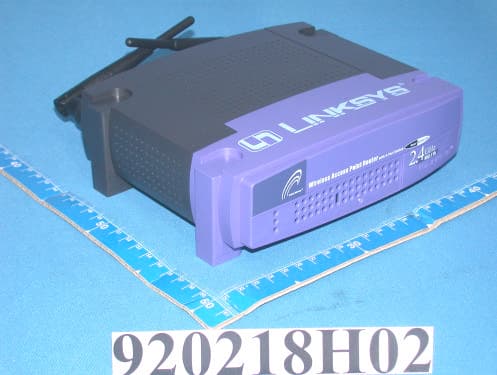
PKW-BEFW11S4V32
Apr 13, 2003Wireless Access Point Router with 4-Port Switch
Equipment Class
DTS - Digital Transmission System
PKW-WSB24-2
Apr 03, 2003Wireless Signal Booster
Equipment Class
DTS - Digital Transmission System
PKW-BEFCMUH4
Apr 01, 2003Cable Gateway
Equipment Class
DTS - Digital Transmission System