PKW-WPC11-V31Wireless Network PC Radio Card
Cisco-Linksys, LLC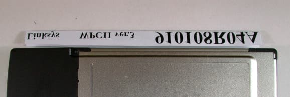
Click to zoom
Application Details
- Equipment Class
- DTS - Digital Transmission System
- Date of Grant
- Jul 22, 2002
- Application Purpose
- Original Equipment
- Date of Application
- Jul 22, 2002
- Equipment Note
- Wireless Network PC Radio Card
- Frequency Range
- 2412.00000000 - 2462.00000000
- Company
- Cisco-Linksys, LLC
- Country
- United States
Documents & Files
Document Text
Text extracted from the exhibit documents filed with the FCC. Open a document above to read the original.
Users Manual
Inform Letter Dear Customer, According to FCC’s regulation, the following Declaration of Conformity has to be made by a company located in USA. They are: This device has been confirmed to be in compliance with the requirements of ANSI C63.4 & FCC part 15 regulations. The test result has been shown in the ADT test report with number RF910529R03. And this compliance is subject to the following two conditions: (1) This device may not cause harmful interference and, (2) This device must accept any interference received, including interference that may cause undesired operation. This declaration can be a separate sheet and be sure that the following message will be also included in this declaration: 1) Product name, model name and trade name. 2) Company name, and address of the one who is responsible for this declaration. 3) Name, title, telephone and fax number as well as the signature of the contact person. Thanks for your attention.
Users Manual
Instant Wireless TM Series Network PC Card User Guide Use this Guide to install: WPC11 ver. 3.0 COPYRIGHT & TRADEMARKS Copyright © 2002 Linksys, All Rights Reserved. Instant Wireless™ is a registered trade- mark of Linksys. Microsoft, Windows, and the Windows logo are registered trademarks of Microsoft Corporation. All other trademarks and brand names are the property of their respective proprietors. LIMITED WARRANTY Linksys guarantees that every Instant Wireless™ Network PCCard ver. 3.0 is free from physical defects in material and workmanship for one year from the date of purchase, when used within the limits set forth in the Specifications chapter of this User Guide. If these products prove defective during this warranty period, call Linksys Technical Support in order to obtain a Return Authorization Number. BE SURE TO HAVE YOUR PROOF OF PURCHASE AND A BARCODE FROM THE PRODUCT’S PACKAGING ON HAND WHEN CALLING. RETURN REQUESTS CANNOT BE PROCESSED WITHOUT PROOF OF PURCHASE. When returning a product, mark the Return Authorization Number clearly on the outside of the package and include your original proof of pur- chase. All customers located outside of the United States of America and Canada shall be held responsible for shipping and handling charges. IN NO EVENT SHALL LINKSYS’ LIABILITY EXCEED THE PRICE PAID FOR THE PROD- UCT FROM DIRECT, INDIRECT, SPECIAL, INCIDENTAL, OR CONSEQUENTIAL DAM- AGES RESULTING FROM THE USE OF THE PRODUCT, ITS ACCOMPANYING SOFT- WARE, OR ITS DOCUMENTATION. LINKSYS DOES NOT OFFER REFUNDS FOR ANY PRODUCT. Linksys makes no warranty or representation, expressed, implied, or statuto- ry, with respect to its products or the contents or use of this documentation and all accompanying software, and specifically disclaims its quality, performance, mer- chantability, or fitness for any particular purpose. Linksys reserves the right to revise or update its products, software, or documentation without obligation to notify any individ- ual or entity. Please direct all inquiries to: Linksys P.O. Box 18558, Irvine, CA 92623. FCC STATEMENT This product has been tested and complies with the specifications for a Class B digital device, pursuant to Part 15 of the FCC Rules. These limits are designed to provide rea- sonable protection against harmful interference in a residential installation. This equip- ment generates, uses, and can radiate radio frequency energy and, if not installed and used according to the instructions, may cause harmful interference to radio communi- cations. However, there is no guarantee that interference will not occur in a particular installation. If this equipment does cause harmful interference to radio or television reception, which is found by turning the equipment off and on, the user is encouraged to try to correct the interference by one or more of the following measures: • Reorient or relocate the receiving antenna • Increase the separation between the equipment or devices • Connect the equipment to an outlet other than the receiver’s • Consult a dealer or an experienced radio/TV technician for assistance Table of Contents Chapter 1: Introduction1 The Instant Wireless TM Network PCCard ver. 3.01 Features1 Package Contents 2 System Requirements2 Chapter 2: Planning Your Wireless Network3 Network Topology3 Roaming3 Chapter 3: Installing the Drivers and Configuration Utility for Windows 95, 98, ME and 20004 Before You Start4 Running the Auto Driver Installation4 Ad-Hoc Versus Infrastructure Mode8 Infrastructure Mode9 Ad-Hoc Mode11 Chapter 4: Installing the Drivers and Configuration Utility for Windows XP14 Chapter 5: Installing the Network PC Card16 Chapter 6: Installing the Drivers and Configuration Utility for Windows NT17 Overview17 Installing the Network PC Card in Your Notebook PC17 Installing the Drivers for Windows NT18 Installing the Configuration Utility for Windows NT30 Chapter 7: Configuration Utility30 Using the Configuration Utility30 Chapter 8: Installing Network Protocols39 Network PC Card Instant Wireless TM Series Chapter 9: Advanced Properties41 Advanced Properties for Windows 95, 98, ME, and 200041 Advanced Properties for Windows NT49 Chapter 10: Troubleshooting56 Common Problems and Solutions56 Frequently Asked Questions57 Chapter 11: Glossary61 Chapter 12: Specifications68 Environmental 68 Chapter 13: Warranty Information69 Chapter 14: Contact Information70 2 • One Instant Wireless TM Network PC Card ver. 3.0 • One Setup Utility CD-ROM (User Guide on CD) • Quick Installation insert and Registration Card (not shown) • A 16-bit PCMCIA Type IIor Type IIIslot • PCMCIA revisions 2.10 compliant card and socket services • Windows 95, 98, Millennium, NT, 2000, or XP • 600 Kbytes of free disk space for utility and driver installation Package Contents System Requirements Instant Wireless TM Series 1 Chapter 1: Introduction Put the “mobile” back into mobile computing! Whether you’re at your desk or in the boardroom, the Instant Wireless™ Network PC Card allows you to share printers, files, and other resources anywhere within your LAN infrastructure, increasing your productivity and keeping you “in touch.” The Instant Wireless™ Network PC Card now has a new, higher-powered antenna that provides a greater range than ever. The increased sensitivity helps filter out interference and “noise” to keep your signal clear. Improved error correction in the chipset keeps you operating at higher transmission rates for longer distances. And, since you only need one Type II or III PCMCIA slot, you’re free to use your other slots for additional accessories. Ready to run in Type II or III PCMCIA-equipped notebook PCs running Windows 95, 98, Millennium, NT, 2000, and XP, the Instant Wireless™ Network PC Card ver. 3.0 is truly a “must-have” for all notebook PC users. •11 Mbps High-Speed Data Transfer Rate •Compatible with Virtually All Major Network Operating Systems •Plug-and-Play Operation Provides Easy Setup •Integrated Equalizer Recovers Weak Signals a…
Text truncated - open the document above for the full version.
Users Manual
32 Chapter 7: Configuration Utility The Configuration Utilityis provided to allow you further customization of the Network PCCard and your wireless network. Once the Configuration Utility has been installed, an icon will be placed in the system tray (next to the clock) when the Network PC Card is inserted, as shown in Figure 7-1. You can also start the Configuration Utility by clicking the Startbutton, select- ing Programs, and choosing the folder for the Network PC Card. Choose Configuration Utility. You will see the Wireless LAN Configuration Utility screen (shown in Figure 7-1). This utility is divided into six parts: Link Info, Configuration, Site Survey, Encryption, Advanced, and About. You should change all configuration settings for your Network PC Card using this utility and not under the Network Properties section in your Control Panel. LINK INFO The Link Info screen (shown in Figure 7-2) provides information about the cur- rent link between the Network PC Card and a wireless Access Point. When in Infrastructure Mode, Statewill display the connection statistics for the network segment that you are on. The Current Channelfield shows to what channel the Network PCCard is set. The Current Transfer Ratefield shows the transfer rate in megabits per sec- ond. TheCurrent Service Set Identifiershows the current SSID set for the wire- less network. This SSID can be modified at the Configurationscreen. The Throughputfields show the rate at which data is transferred and received in Bytes per second. Using the Configuration Utility Figure 7-1 If this screen does not appear automatically, you can access the installation by clicking the Start button and choosing Run. In the drop-down box provided, type D:\setup.exe(where D: is the letter of your CD-ROM drive). Alternately, double-click My Computer, and then double-click the CD-ROM drive where the Setup Utility CD is located. Double-click the Setup.exeicon that appears. Follow the instructions that appear on your screen. If you have any questions or difficulty, refer to the section called Installing the Drivers and Configuration Utility for Windows 95, 98, ME, and 2000. Network PC Card Instant Wireless TM Series 31 34 CONFIGURATION The Configuration screen, shown in Figure 7-3, allows you to customize the settings for the Network PCCard and your wireless network. The Wireless Modesetting determines the architecture of your wireless net- work. Select Ad-Hocor InfrastructureMode depending on your network type. The Ad-Hocmode is used for a simple peer-to-peer network and allows the sharing of local resources only between Network PCCards without need- ing a wireless Access Point. The Infrastructuremode allows a wireless net- work to be integrated into an existed, wired network through an Access Point. Infrastructure networks permit roaming between Access Points while main- taining a connection to all network resources. An acronym for Service Set Identifier, SSIDis the unique name shared among all points in a wireless network. The SSID must be identical for all points in the network. It is case sensitive and must not exceed 32 characters. Figure 7-3 The Link Qualityfield will display a bar indicating the percentage, between 0 and 100 percent, of the quality of the link. The higher the percentage, the bet- ter the link. The Signal Strengthfield will display a bar indicating the percentage, between 0 and 100 percent, of the strength of the signal. The higher the percentage, the stronger the signal. Note: When in Ad-Hoc mode, Link Quality and Signal Strength indicators will not be available. Figure 7-2 Network PC Card Instant WirelessSeries 33 35 ENCRYPTION On the Encryption screen, shown in Figure 7-5, you can set the level of security with which you will be using the Network PC Card. Under the drop-down box, you can choose to have WEP encryption Disabled, 64- Bit, or 128-Bit. Wired Equivalent Privacy (WEP) is an encryption scheme used to protect wireless data communication. The Disabled setting prevents the sharing of data with other computers on the WEP network. When selecting Manual Entry for the WEP Key Entry, enter the hexadecimal number set by other wireless WEP settings; these settings have to be identical to the WEP encryption on all points in your wireless network in order to network to yourNetwork PC Card. Note:In order to enable WEP encryption, hexadecimal values must be entered. Figure 7-5 Note:The WEP Key Entry must match the Key on all other devices on the wireless network, or else this device will be unable to trans- mit or receive data. The Transfer Rate field shows the current transfer rate for the Network PC Card. To optimize performance and range, the TX Rate should be set to Fully Automatic, which will automatically adjust the transfer speed for best per- formance and longest range. The Channelsetting specifies the channel used in wireless communication and should be set to the same channel as the other points in the wireless network. This setting can only be adjusted in Ad-Hoc mode. Power Saving Mode, or PS Mode, enables or disables the power saving features of your Network PCCard. SITESURVEY The Site Survey screen shows the available access points and their features. Click on the desired access point. Then click Connectto connect or Searchto search for more access points. Network PC Card Figure 7-4 Instant Wireless TM Series 36 37 The RTS Threshold Valueshould remain at its default setting of 2,432. A pre- amble is a signal used to synchronize the transmission timing between two or more systems. A series of transmission pulses is sent before the data to indicate that “someone is about transmit data.” This ensures that systems receiving the information correctly when the data transmission starts. Securityis used for WEP only. By selecting Deny Unencrypted Data Frames, all unencrypted data will not be seen. For Authentication Type, you may choose between Open Systemor Shared Key. Shared Keyis when both the sender and recipient sha…
Text truncated - open the document above for the full version.
Cover Letter(s)
American Telecommunications Certification Body Inc. 6731 Whittier Ave, McLean, VA 22101 July 23, 2002 RE: THE LINKSYS GROUP, INC. FCC ID: PKW-WPC11-V31 After a review of the submitted information, I have a few comments on the above referenced Application. Please Note that SAR issued will be issued under a separate letter. 1) Please submit a DTS cover letter for this project. 2) The elements to each antenna are slightly different. Is the device capable of transmitting out of both antennas, or is one antenna only used for receive only? 3) The test report states that the EUT is designed with 2 outer appearances. Please provide specific information as to what these differences are. Are any of the differences changes in the metal, plastic, etc. 4) Please update the EMC test report (page 44) to provide the calculations for the 3.9 GHz bandedge as well. Timothy R. Johnson Examining Engineer Direct Phone: 404-414-8071 mailto: [email protected] The items indicated above must be submitted before processing can continue on the above referenced application. Failure to provide the requested information may result in application termination. Correspondence should be considered part of the permanent submission and may be viewed from the Internet after a Grant of Equipment Authorization is issued. Please do not respond to this correspondence using the email reply button. In order for your response to be processed expeditiously, you must submit your documents through the AmericanTCB.com website. Also, please note that partial responses increase processing time and should not be submitted. Any questions about the content of this correspondence should be directed to the sender.
Cover Letter(s)
Dear Tim, For item 1,4, please find uploaded files on your website. For item 2, another antenna only used for receive. For item 3, This EUT is designed with one outer appearance only. Regards, Rennie ----- Âà§eªÌ Rennie Wang/ADT ©ó 2002/07/24 01:40 PM ----- "Timothy R. Johnson" ¦¬¥ó¤H¡G [email protected] <tjohnson@Americ °Æ¥»§Û°e¡G [email protected], [email protected] anTCB.com> ¥D¦®¡G EMC Review of The Linksys Group, Inc., FCC ID: PKW-WPC11-V31 2002/07/23 01:23 PM Alan, Attached are comments regarding review of this application. Please provide information as soon as possible. Thank You, Timothy R. Johnson NARTE Certified EMC Engineer No. EMC-002205-NE email: [email protected] alternate email: [email protected] (See attached file: ATCB Comments_072202_EMC.pdf) =big5BQVRDQiBDb21tZW50c18wNzIyMDJfRU1DLnBkZg===1.pdf To: [email protected] Subject: EMC Review of The Linksys Group, Inc., FCC ID: PKW-WPC11-V31 Page 1 of 1In 7/26/2002Printed for "Timothy R. Johnson" <[email protected]>
Cover Letter(s)
American Telecommunications Certification Body Inc. 6731 Whittier Ave, McLean, VA 22101 July 23, 2002 RE: THE LINKSYS GROUP INC. FCC ID: PKW-WPC11-V31 After a review of the submitted information, I have a few comments on the above referenced Application. 1) The Maximum output power (conducted) or SAR drift measured at same position in liquid before and after each SAR test must be shown on each SAR plot? Please update the report to include this. 2) Test report must state (recommended on page 19 of 30): a) Identification of the device (was it considered mobile or portable transmitter device category) b) whether test device is production unit or identical prototype (47 CFR §2.908)? 3) Please provide a means to verify a phantom liquid depth. Depth must be 15 cm or more, per suppl. C and draft IEEE STD 1528. Please use photos, SAR vs. depth data (z-axis scan), or other means to demonstrate/verify liquid depth. 4) IEEE STD 1528 requires that the SAR test be performed at the high, middle, and low frequency channels of each operating mode. However, if the SAR measured at the middle channel for each test configuration is at least 2.0 dB lower than the SAR limit, testing at the high channels is optional (Note: this procedure is stated on page 6 & 17 of 30. The data provided is for the low channel only. Please provide data for the middle channel. 5) Please provide a description of the material/holder used to support the laptop. 6) Please justify and explain the use of a crest factor of 8. 7) A z-axis scan at the max SAR location must be provided. 8) OET Bulletin 65, Supplement C make mention of using the Flat Phantom Box for system verification. Please justify the use of this box for over the SAM phantom containing a flat body cavity. 9) Description of the phantom should detail shell thickness and other tolerances necessary to show it meets the phantom shell specifications. 10) Scan procedures given in the report appear to be for different phantoms. Please explain for the course scan: a) descriptions of coarse area scan procedures, including grid size, area shape and size b) specify which peak SAR location(s) were used to evaluate max 1-g SAR(s) c) report probe tip distance to phantom inner surface 11) Scan procedures given in the report appear to be for different phantoms. Please explain for the "zoom" scan: a) descriptions of high-resolution cube volume or “zoom” scan procedures used for local scan; list measurement and interpolation resolutions 12) The tissue parameters appear to be that of head tissue and not body tissue, please explain. 13) The tissue dielectric parameters and temperature should be measured at device mid-band frequencies. It appears that these were performed at the lower frequency. 14) SAR Plots must show: a) Ambient and liquid temperatures b) liquid temperatures during SAR testing must stay within ± 2° C. 15) The Tissue Parameters given on page 20 do not appear to match the parameters given on the test plots. Please explain. 16) Page 17 of 30 mentions "the above mentioned power values are conducted measured values..." . There is not any reported power values on this page. 17) Please provide a brief description of the reference source (e.g., 900, 1800 MHz dipoles) used to verify the SAR system performance. 18) Please provide the manufacturer/calibration reference dipole data. 19) Regarding the Field Probe: a) description of the probe – including tip diameter, internal sensor offset from tip, etc b) description of the probe measurement errors c) Description of probe calibration errors/uncertainties d) Please provide most recent calibration date and calibration certificate showing all factors used in report. - Continued on Next Page - z Page 2July 23, 2002 20) A list of measured tissue dielectric parameters, ambient and tissue temperatures must be provide for the system verification. These values must be within 5% of the values used in system manufacturer’s reference test. Timothy R. Johnson Examining Engineer Direct Phone: 404-414-8071 mailto: [email protected] The items indicated above must be submitted before processing can continue on the above referenced application. Failure to provide the requested information may result in application termination. Correspondence should be considered part of the permanent submission and may be viewed from the Internet after a Grant of Equipment Authorization is issued. Please do not respond to this correspondence using the email reply button. In order for your response to be processed expeditiously, you must submit your documents through the AmericanTCB.com website. Also, please note that partial responses increase processing time and should not be submitted. Any questions about the content of this correspondence should be directed to the sender.
Cover Letter(s)
American Telecommunications Certification Body Inc. 6731 Whittier Ave, McLean, VA 22101 August 1, 2002 RE: BROMAX COMMUNICATIONS, INC. FCC ID: PKW-WPC11-V31 After a review of the submitted information, I have a few comments on the above referenced Application. 1) Most device are placed underneath the phantom and the liquid depth above is specified to be 15 cm. However, this device was tested from the side of the box (vs. underneath) and therefore the distance as you move away from the device through the liquid (in this case will be horizontally) does not appear to give you 15 cm. Please justify acceptance of testing from the side of the box vs. underneath the box, given the liquid does not provide a 15 cm 'depth' as you move transversely away from the device. 2) Is manufacturer/calibration plots available for the dipole used for system verification that includes a list of measured tissue dielectric parameters, ambient and tissue temperatures during the calibration. These values (ε & σ) should be within 5% of those used during testing. 3) The test report only provides test data for the lowest channel. However the procedure given in the test report (which also match 1528/supplement C) on page 6 of 30 (last paragraph) and page 17 of 30 (last paragraph) state that the middle channel is tested first and if this is at least 2 dB below the SAR limit, the high and low channel is optional. Please provide further justification for only providing data for the lowest channel. 4) A field probe must be calibrated in tissue media with the target dielectric parameters specified in Appendix C of IEEE 1528, corresponding to the operating frequency ranges of the test device. Probe conversion factors by extrapolation is not allowed for TCB approval and the calibration should be performed within 5% target dielectric property window for the testing performed (dielectric information was not specified in calibration information). Please provide probe calibration information for the 2.4 GHz band measured. Also please note that the SAR correction factors listed in the report and were used are not exactly as those that appear on the calibration information already provided. 5) The test report claims a Crest Factor of 8. We understand that you are awaiting justification from the manufacturer. 6) When measuring pulsed signals with low duty factors or high peak-to-average ratios, the probe must be calibrated with correction factors to accurately measure SAR with respect to the average power. Given a Crest Factor of 8, please provide information regarding the probes correction factors for low duty cycles. Timothy R. Johnson Examining Engineer Direct Phone: 404-414-8071 mailto: [email protected] The items indicated above must be submitted before processing can continue on the above referenced application. Failure to provide the requested information may result in application termination. Correspondence should be considered part of the permanent submission and may be viewed from the Internet after a Grant of Equipment Authorization is issued. Please do not respond to this correspondence using the email reply button. In order for your response to be processed expeditiously, you must submit your documents through the AmericanTCB.com website. Also, please note that partial responses increase processing time and should not be submitted. Any questions about the content of this correspondence should be directed to the sender.
Cover Letter(s)
Hi Tim, Please find the attached three files for Q2,4 and 6. I am still waiting for Q 5 from BroMax If you can get from them? Liming > > Question 2) > I attach our performance statement for the dipoles supplied > (IXS0212.doc). > > Question 4) > I attach (SN0082cal2450.doc) a document setting out calibration > factors to be used at 2450MHz until such time as this probe receives its > next calibration. > > Question 6) > The pulsed performance of Indexsar probes is covered in the original > calibration document. This indicated, for probe 0082, that pulsed signals > would be correctly measured using the calibration supplied for CW signals. > > <<SN0082cal2450.doc>> <<SN0016_1900.doc>> <<IXS0212 new.doc>> SN0082cal2450.doc SN0016_1900.doc IXS0212 new.doc To: "'Timothy R. Johnson'" <[email protected]> Subject: RE: Questions 2,4 and 6 Page 1 of 1In Printed for "Timothy R. Johnson" <[email protected]>
Cover Letter(s)
American Telecommunications Certification Body Inc. 6731 Whittier Ave, McLean, VA 22101 RE: THE LI NKSYS GROUP INC. FCC ID: PKW-WPC11-V31 After a review of the submitted information, I have a few comments on the above referenced Application. 1) The Maximum output power (conducted) or SAR drift measured at same position in liquid before and after each SAR test must be shown on each SAR plot? Please update the report to include this. Corrected in the report. 2) Test report must state (recommended on page 19 of 30): A) Identification of the device (was it considered mobile or portable transmitter device category B whether test device is production unit or identical prototype (47 CFR §2.908)? Corrected in the report 3) Please provide a means to verify a phantom liquid depth. Depth must be 15 cm or more, per suppl. C and draft IEEE STD 1528. Please use photos, SAR vs. depth data (z- axis scan), or other means to demonstrate/verify liquid depth. Corrected in the report 4) -- IEEE STD 1528 requires that the SAR test be performed at the high, middle, and low frequency channels of each operating mode. However, if the SAR measured at the middle channel for each test configuration is at least 2.0 dB lower than the SAR limit, testing at the high channels is optional (Note: this procedure is stated on page 6 & 17 of 30. The data provided is for the low channel only. Please provide data for the middle channel. Per supplement C, the SAR test is performed for the highest EIRP value channel, which in this case is the lowest channel. The final SAR value is significantly lower than limit , (less than 2 dB) therefore measurement is done for only one channel (in this case the low channel) and the measurement for other 2 channels is optional. 5) --- Please provide a description of the material/holder used to support the laptop. See report page 10. The material used is ROHACELL 51HF. Dielectric properties are: 1.057 @ 2.5GHZ and 1.065 @ 5GHz. Loss Tangent is <.0002 at 2.5GHz. 6) Please justify and explain the use of a crest factor of 8. Waiting for answer from Bromax. 7) A z-axis scan at the max SAR location must be provided. Please note all the plots provided(pages 27 & 28) have Z-axis scan, which is in the SARA2 output for both area and zoom scans. 8) OET Bulletin 65, Supplement C make mention of using the Flat Phantom Box for system verification. Please justify the use of this box for over the SAM phantom containing a flat body cavity. The Flat Phantom Box supplied by IndexSAR meets the dielectric and dimensional requirements of IEEE1528. Now here does any specification specifically identify the flat area of the TWIN SAM as the phantom of choice. No justification is needed. 9) Description of the phantom should detail shell thickness and other tolerances necessary to show it meets the phantom shell specifications. The shell thickness is 2mm. Please see page 13 of the test report. 10) Scan procedures given in the report appear to be for different phantoms. Please explain for the course scan: a) descriptions of coarse area scan procedures, including grid size, area shape and size b) specify which peak SAR location(s) were used to evaluate max 1-g SAR(s) c) report probe tip distance to phantom inner surface 11) Scan procedures given in the report appear to be for different phantoms. Please explain for the "zoom" scan: Questions no 10 & 11 are unclear a) descriptions of high-resolution cube volume or “zoom” scan procedures used for local scan; list measurement and interpolation resolutions 12) The tissue parameters appear to be that of head tissue and not body tissue, please explain. This was a typographical error in the original report which has been corrected in the updated report. 13) The tissue dielectric parameters and temperature should be measured at device mid- band frequencies. It appears that these were performed at the lower frequency. The parameters were measured at 2.45GH and the response was very flat throughout the whole frequency band. 14) SAR Plots must show: a) Ambient and liquid temperatures b) liquid temperatures during SAR testing must stay within ± 2 ° C. This was an omission in the original report which has been corrected in the updated report. 15) The Tissue Parameters given on page 20 do not appear to match the parameters given on the test plots. Please explain. This was a typographical error in the original report which has been corrected in the updated report. 16) Page 17 of 30 mentions "the above mentioned power values are conducted measured values..." . There is not any reported power values on this page. This was a typographical error in the original report which has been corrected in the updated report. 17) Please provide a brief description of the reference source (e.g., 900, 1800 MHz dipoles) used to verify the SAR system performance. Used the IEEE1528 std, specified reference dipoles (by the way we used the dipole for 2.45 GHz). Liming please EXPAND on the rest of the source...Please see page 21 of 30 on The report. 18) Please provide the manufacturer/calibration reference dipole data. See the attachments. 19) Regarding the Field Probe: a) description of the probe – including tip…
Text truncated - open the document above for the full version.
Contact Information
Applicant
Ms Jennifer Yu(Associate Engineer)
Technical Contact
Advance Data Technology CorporationAlan Lane
[email protected]+886-3-327-0910
13-1, Lane 19, WenShan 3rd., St. · Taoyuan · Taiwan
Non-Technical Contact
Advance Data Technology CorporationAlan Lane
[email protected]+886-3-327-0910
Test Firm
Bureau Veritas CPS (H.K.) Ltd. Taoyuan BranchTommy Wu
Technical Specifications
| # | Rule Parts | Frequency Range | Power Output |
|---|---|---|---|
| 1 | 15C | 2.41 GHz - 2.46 GHz | 70.00 mW |
Other Applications from Cisco-Linksys, LLC

PKW-WMP54GV2
May 29, 2003Wireless-G PCI Adapter
Equipment Class
DTS - Digital Transmission System
PKW-BEFW11S4V4
May 21, 2003Wireless Access Point Router
Equipment Class
DTS - Digital Transmission System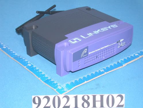
PKW-BEFW11S4V32
Apr 13, 2003Wireless Access Point Router with 4-Port Switch
Equipment Class
DTS - Digital Transmission System
PKW-WSB24-2
Apr 03, 2003Wireless Signal Booster
Equipment Class
DTS - Digital Transmission System
PKW-BEFCMUH4
Apr 01, 2003Cable Gateway
Equipment Class
DTS - Digital Transmission System