PKW-WPC11-V4Wireless-B Notebook Adapter
Cisco-Linksys, LLC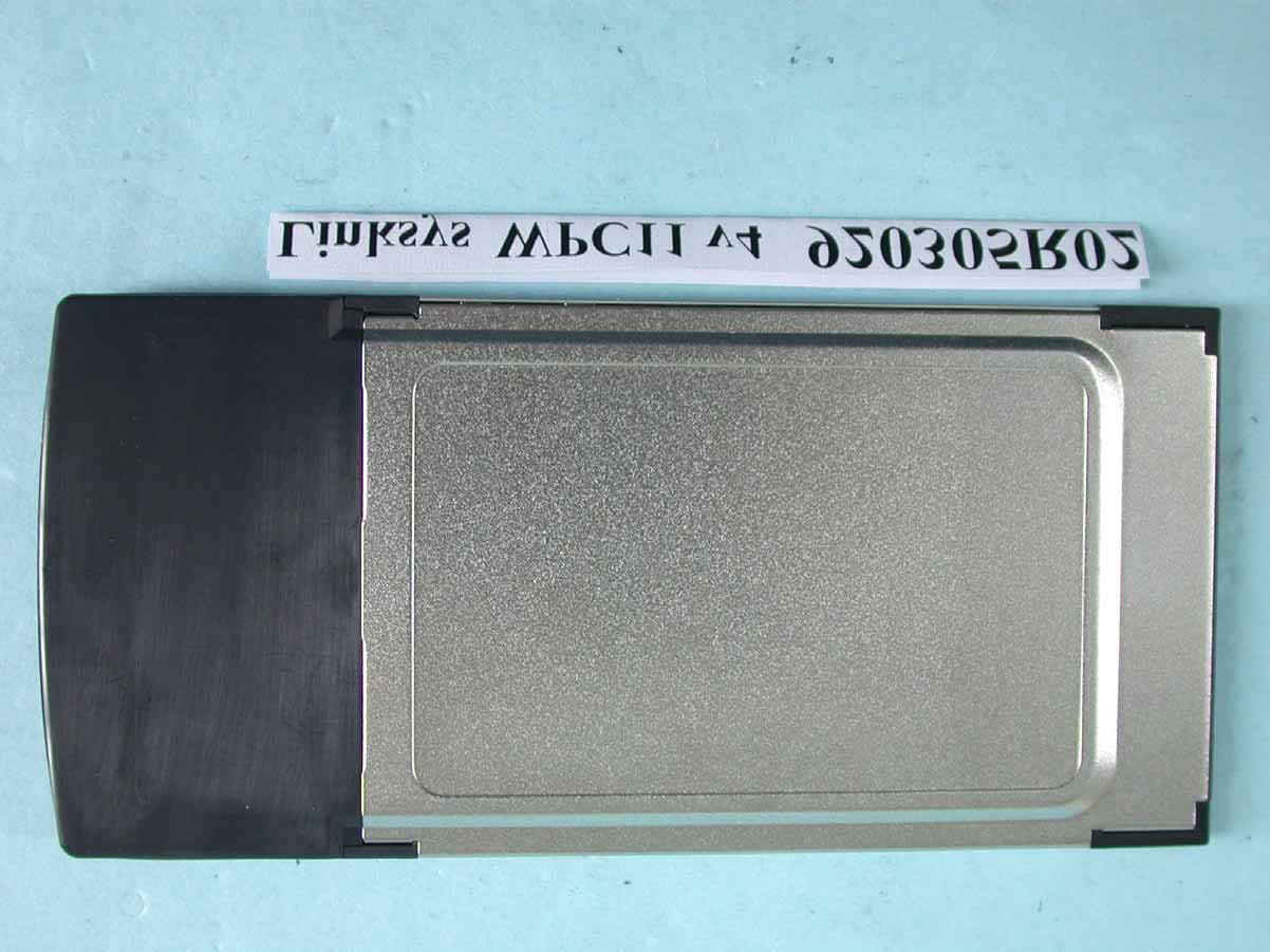
Click to zoom
Application Details
- Equipment Class
- DTS - Digital Transmission System
- Date of Grant
- Mar 11, 2003
- Application Purpose
- Original Equipment
- Date of Application
- Mar 11, 2003
- Equipment Note
- Wireless-B Notebook Adapter
- Frequency Range
- 2412.00000000 - 2462.00000000
- Company
- Cisco-Linksys, LLC
- Country
- United States
Documents & Files
Document Text
Text extracted from the exhibit documents filed with the FCC. Open a document above to read the original.
Users Manual
Table of Contents Chapter 1: Introduction1 The Instant Wireless TM Network PCCard ver. 3.01 Features1 Package Contents 2 System Requirements2 Chapter 2: Planning Your Wireless Network3 Network Topology3 Roaming3 Chapter 3: Installing the Drivers and Configuration Utility for Windows 95, 98, ME and 20004 Before You Start4 Running the Auto Driver Installation4 Ad-Hoc Versus Infrastructure Mode8 Infrastructure Mode9 Ad-Hoc Mode11 Chapter 4: Installing the Drivers and Configuration Utility for Windows XP14 Chapter 5: Installing the Network PC Card16 Chapter 6: Installing the Drivers and Configuration Utility for Windows NT17 Overview17 Installing the Network PC Card in Your Notebook PC17 Installing the Drivers for Windows NT18 Installing the Configuration Utility for Windows NT30 Chapter 7: Configuration Utility30 Using the Configuration Utility30 Chapter 8: Installing Network Protocols39 Network PC Card Instant Wireless TM Series Chapter 9: Advanced Properties41 Advanced Properties for Windows 95, 98, ME, and 200041 Advanced Properties for Windows NT49 Chapter 10: Troubleshooting56 Common Problems and Solutions56 Frequently Asked Questions57 Chapter 11: Glossary61 Chapter 12: Specifications68 Environmental 68 Chapter 13: Warranty Information69 Chapter 14: Contact Information70 2 • One Instant Wireless TM Network PC Card ver. 3.0 • One Setup Utility CD-ROM (User Guide on CD) • Quick Installation insert and Registration Card (not shown) • A 16-bit PCMCIA Type IIor Type IIIslot • PCMCIA revisions 2.10 compliant card and socket services • Windows 95, 98, Millennium, NT, 2000, or XP • 600 Kbytes of free disk space for utility and driver installation Package Contents System Requirements Instant Wireless TM Series 1 Chapter 1: Introduction Put the “mobile” back into mobile computing! Whether you’re at your desk or in the boardroom, the Instant Wireless™ Network PC Card allows you to share printers, files, and other resources anywhere within your LAN infrastructure, increasing your productivity and keeping you “in touch.” The Instant Wireless™ Network PC Card now has a new, higher-powered antenna that provides a greater range than ever. The increased sensitivity helps filter out interference and “noise” to keep your signal clear. Improved error correction in the chipset keeps you operating at higher transmission rates for longer distances. And, since you only need one Type II or III PCMCIA slot, you’re free to use your other slots for additional accessories. Ready to run in Type II or III PCMCIA-equipped notebook PCs running Windows 95, 98, Millennium, NT, 2000, and XP, the Instant Wireless™ Network PC Card ver. 3.0 is truly a “must-have” for all notebook PC users. •11 Mbps High-Speed Data Transfer Rate •Compatible with Virtually All Major Network Operating Systems •Plug-and-Play Operation Provides Easy Setup •Integrated Equalizer Recovers Weak Signals and Enhances Sensitivity •Sturdy Metal Design with Integrated Antenna •Works with All Standard Internet Applications •Interoperable with IEEE 802.11b (DSSS) 2.4GHz-Compliant Equipment •Clear Channel Assessment Increases Network Throughput •Hardware Buffer Chaining Provides High Performance While Reading and Writing Buffers •Capable of up to 128-Bit WEP •Free Technical Support—24 Hours a Day, 7 Days a Week for North America Only •1-Year Limited Warranty Features The Instant Wireless TM Network PC Card ver. 3.0 Figure 1-1 Network PC Card 43 Chapter 3: Installing the Drivers and Configuration Utility for Windows 95, 98, ME, and 2000 Your new Linksys Instant Wireless™ Network PC Card ver. 3.0 comes with an automated software installation procedure for Windows 95, 98, Millennium, and 2000. Windows NTor XP users should refer to the next section.This new procedure automatically installs the drivers and Configuration Utility beforeyou insert the Card into your PC, so there’s no searching for the location of drivers. Again, this step is taken before inserting the Card into your PC. 1.Before installing your card, insert the Setup Utility CD into your CD-ROM drive. Unless you have deactivated the auto-run feature of Windows, the screen shown in Figure 2-1 should appear automati- cally. If this screen does not appear automatically, you can access the installation by clicking the Start button and choosing Run. In the drop-down box pro- vided, type D:\setup.exe(where D: is the letter of your CD-ROM drive). Alternately, double-click My Computerand double-click the CD-ROM drive where the Setup Utility CD is located. Double-click the Setup.exeicon in the folder that appears. Before You Start Running the Auto Driver Installation Network PC Card Chapter 2: Planning Your Wireless Network Awireless LAN is exactly like a regular LAN, except that each computer in the LAN uses an Instant Wireless™ Network PC Card ver. 3.0 to connect to the network through a wireless connection. Computers in a wireless LAN must be configured to share the same radio channel. The Instant Wireless™ Network PC Card ver. 3.0 provides LAN access for wireless workstations. An integrated wireless and wired LAN is called an Infrastructure configuration. A group of Instant Wireless™ Network PC Card ver. 3.0 users and an Access Point compose a Basic Service Set (BSS). Each PCequipped with an Instant Wireless™ Network PC Card ver. 3.0 in a BSS can talk to any computer in a wired LAN infrastructure via the Access Point. An infrastructure configuration extends the accessibility of an Instant Wireless™ Network PC Card ver. 3.0 PC to a wired LAN, and doubles the effective wireless transmission range for two PCs equipped with an Instant Wireless™ Network PC Card ver. 3.0. Since the Access Point is able to for- ward data within its BSS, the effective transmission range in an infrastructure LAN is doubled. Infrastructure mode also supports roaming capabilities for mobile users. More than one BSS can be configured as an Extended Service Set (ESS). This con- tinuous network allows users to roam freely within an …
Text truncated - open the document above for the full version.
Cover Letter(s)
[email protected] www.adt.com.tw ADVANCE DATA TECHNOLOGY CORPORATION FEDERAL COMMUNICATIONS COMMISSION DECLARATION OF CONFORMITY (DoC) FOR THE FOLLOWING EQUIPMENT: PRODUCT NAME: Wireless-B Notebook Adapter (Receiver Part) MODEL NO.: WPC11 v4 TRADE NAME: Linksys IS HEREWITH CONFIRMED AND FOUND TO COMPLY WITH THE REQUIREMENTS OF CFR 47 PART 15 REGULATION. THE RESULTS OF ELECTROMAGNETIC EMISSION EVALUATION ARE SHOWN IN THE REPORT NO.: D920305R02 THIS DEVICE COMPLIES WITH PART 15 OF THE FCC RULES. OPERATION IS SUBJECT TO THE FOLLOWING TWO CONDITIONS: (1) THIS DEVICE MAY NOT CAUSE HARMFUL INTERFERENCE AND, (2) THIS DEVICE MUST ACCEPT ANY INTERFERENCE RECEIVED, INCLUDING INTERFERENCE THAT MAY CAUSE UNDESIRED OPERATION. THE FOLLOWING LOCAL MANUFACTURER/IMPORTER IS RESPONSIBLE FOR THIS DECLARATION: ManufacturerUSA Local Representative Company name: The Linksys Group, INC. Company name: The Linksys Group, INC. Address: 17401 Armstrong Ave. Irvine, CA 92614 Address: 17401 Armstrong Ave. Irvine, CA 92614 Contact Person: Ben Sakai Contact Person: Ben Sakai Title: Serior Manager of Product Management Title: Serior Manager of Product Management Tel/Fax: Tel: 949-748-1803 Fax: 949-261-8868 Tel/Fax: Tel: 949-748-1803 Fax: 949-261-8868
External Photos
Page 1 ANNEX PHOTOGRAPHS OF EUT Page 2
Internal Photos
Page 3 Page 4 Page 5
Operational Description
FCC ID: PKW-WPC11-V4 ADT No.920305R02 Operational Description The transmitter of the EUT is powered by host equipment. The antenna is PCB antenna without connector. The other instruction, please have a look at the users manual. DSSS Information This device is Direct Sequence Spread Spectrum, the data is mixed by pseudorandom code which is an orthogonal code. The mixed data is digital modulated by BPSK and QPSK technique depends on the data rates. The CCK coding is applied for increasing the data rate, and also the processing gain will be increased. The bit rates are 1,2,5.5,11Mbps, the symbol rates are 1,1,1.375,1.375Mbps, the chip rates are always 11Mbps. So, the Chip/symbol is 11,11,8 and 8 respectively. Although is higher bit rate, the processing gain is lower than 10, but the CCK coding used in higher bit rate will provide 2.2dB coding gain.
RF Exposure Info
FCC ID: PKW-WPC11-V4 Report No.: SA920305R02 1 Issued: March. 10 th 2003 SAR TEST REPORT REPORT NO.: SA920305R02 MODEL NO.: WPC11 v4 RECEIVED: March. 07, 2003 TESTED: March. 07, 2003 APPLICANT: The Linksys Group, INC. ADDRESS:17401 Armstrong Ave. Irvine, CA92614 ISSUED BY:Advance Data Technology Corporation LAB LOCATION:47 14th Lin, Chiapau Tsun, Linko, Taipei, Taiwan, R.O.C. This test report consists of 15 pages in total except Appendix. It may be duplicated completely for legal use with the approval of the applicant. It should not be reproduced except in full, without the written approval of our laboratory. The client should not use it to claim product endorsement by CNLA, NVLAP or any government agencies. The test results in the report only apply to the tested sample. FCC ID: PKW-WPC11-V4 Report No.: SA920305R02 2 Issued: March. 10 th 2003 Table of Contents 1.CERTIFICATION .................................................................................................................3 2.GENERAL INFORMATION ................................................................................................. 4 2.1GENERAL DESCRIPTION OF EUT ................................................................................... 4 2.2GENERAL DESCRIPTION OF APPLIED STANDARDS .................................................... 4 2.3GENERAL INOFRMATION OF THE SAR SYSTEM .......................................................... 5 2.4GENERAL DESCRIPTION OF THE PROBE SCAN RULE................................................ 7 3.DESCRIPTION OF TEST MODES AND CONFIGURATIONS ........................................... 8 4.DESCRIPTION OF SUPPORT UNITS ............................................................................... 9 5.TEST RESULTS................................................................................................................ 10 5.1TEST PROCEDURES....................................................................................................... 10 5.2MEASURED SAR RESULT .............................................................................................. 10 5.3SAR LIMITS ...................................................................................................................... 11 5.4EUT CONDUCTED POWER VARIATION ........................................................................ 11 5.5TISSUE ............................................................................................................................. 12 5.6TEST EQUIPMENT FOR TISSUE PROPERTY ............................................................... 12 6.SYSTEM VALIDATION...................................................................................................... 13 7.MEASUREMENT UNCERTAINTIES ................................................................................ 14 8.INFORMATION ON THE TESTING LABORATORIES ..................................................... 15 APPENDIX A: TEST CONFIGURATIONS AND TEST DATA APPENDIX B: ADT SAR MEASUREMENT SYSTEM APPENDIX C: PHOTOGRAPHS OF SYSTEM VALIDATION APPENDIX D: SYSTEM CERTIFICATE & CALIBRATION FCC ID: PKW-WPC11-V4 Report No.: SA920305R02 3 Issued: March. 10 th 2003 1. CERTIFICATION PRODUCT : Wireless-B Notebook Adapter MODEL NO. : WPC11 v4 BRAND NAME : Linksys APPLICANT : The Linksys Group, INC. STANDARDS : 47 CFR Part 2 (Section 2.1093), FCC OET Bulletin 65, Supplement C (01-01), RSS-102 We, Advance Data Technology Corporation, hereby certify that one sample of the designation has been tested in our facility on 07 th March. 2003. The test record, data evaluation and Equipment Under Test (EUT) configurations represented herein are true and accurate, and it was tested according to the standards listed above. This device was found to be in compliance with the Specific Absorption Rate (SAR) requirement specified in FCC part 2.1093 under General Population / Uncontrolled Exposure condition. FCC ID: PKW-WPC11-V4 Report No.: SA920305R02 4 Issued: March. 10 th 2003 2. GENERAL INFORMATION 2.1 GENERAL DESCRIPTION OF EUT PRODUCTWireless-B Notebook Adapter MODEL NO.WPC11 v4 POWER SUPPLY3.3VDC powered by host equipment CLASSIFICATIONPortable device, production unit MODULATION TYPEBPSK, QPSK, CCK RADIO TECHNOLOGYDSSS TRANSFER RATE1/2/5.5/11Mbps FREQUENCY RANGE2412MHz ~ 2462MHz NUMBER OF CHANNEL11 CONDUCTED OUTPUT POWER 66.2Mw ANTENNA TYPEInternal Printed Antenna PEAK SAR0.144W/kg DATA CABLENA I/O PORTSPCMCIA ASSOCIATED DEVICESNA 2.2 GENERAL DESCRIPTION OF APPLIED STANDARDS According to the specifications of the manufacturer, this product must comply with the requirements of the following standards: FCC 47 CFR Part 2 (2.1093) FCC OET Bulletin 65, Supplement C (01- 01) RSS-102 All tests have been performed and recorded as per the above standards. FCC ID: PKW-WPC11-V4 Report No.: SA920305R02 5 Issued: March. 10 th 2003 2.3 GENERAL INOFRMATION OF THE SAR SYSTEM DASY3 (software 3.1d) consists of high precision robtics system, probe alignment sensor, phantom, robot controller, controlled PC and near-field probe. The robot includes six axis that can move to the precision position of the DASY3 software defined. The DASY3 software can define the area which is detected by the probe. The robot is connected to controlled box. Controlled PC is connected to the controlled robot box. The DAE includes amplifier, signal multiplexing, AD converter, offset measurement, surface detection. It is connected to the Electro-optical coupler (ECO). The ECO performs the conversion form the optical into digital electric signal of the DAE and transfers data to the PC. ET3DV6 ISOTROPIC E-FIELD PROBE Construction Symmetrical design with triangular core. Built-in optical fiber for surface detection system. Built-in shielding against static charges. PEEK enclosure material (resistant to organic solvents, e.g., glycolether). Calibration Basic Broad Band Calibration in air: 10-2500 MHz Conversion Factors (CF) for HSL 900 and HSL 1800 CF-Calibration for other liquid…
Text truncated - open the document above for the full version.
Test Report
FCC ID: PKW-WPC11-V4 Report No.: RF920305R02 1 Issued: March 10, 2003 FCC TEST REPORT REPORT NO.: RF920305R02 MODEL NO.: WPC11 v4 RECEIVED: Feb. 21, 2003 TESTED: Feb. 26~ March 6, 2003 APPLICANT:The Linksys Group, Inc. ADDRESS:17401 Armstrong Ave. Irvine, CA 92614 ISSUED BY:Advance Data Technology Corporation LAB LOCATION:47 14th Lin, Chiapau Tsun, Linko, Taipei, Taiwan, R.O.C. This test report consists of 50 pages in total. It may be duplicated completely for legal use with the approval of the applicant. It should not be reproduced except in full, without the written approval of our laboratory. The client should not use it to claim product endorsement by CNLA, NVLAP or any government agencies. The test results in the report only apply to the tested sample. 0528 ILAC MRA Lab Code: 200102-0 FCC ID: PKW-WPC11-V4 Report No.: RF920305R02 2 Issued: March 10, 2003 Table of Contents 1CERTIFICATION ........................................................................................... 4 2SUMMARY OF TEST RESULTS................................................................... 5 3GENERAL INFORMATION ........................................................................... 6 3.1GENERAL DESCRIPTION OF EUT ............................................................. 6 3.2DESCRIPTION OF TEST MODES ............................................................... 7 3.3GENERAL DESCRIPTION OF APPLIED STANDARDS............................... 7 3.4DESCRIPTION OF SUPPORT UNITS.......................................................... 8 4TEST TYPES AND RESULTS ...................................................................... 9 4.1CONDUCTED EMISSION MEASUREMENT ................................................ 9 4.1.1LIMITS OF CONDUCTED EMISSION MEASUREMENT ............................. 9 4.1.2TEST INSTRUMENTS .................................................................................. 9 4.1.3TEST PROCEDURES................................................................................. 10 4.1.4DEVIATION FROM TEST STANDARD ....................................................... 10 4.1.5TEST SETUP ...............................................................................................11 4.1.6EUT OPERATING CONDITIONS................................................................ 12 4.1.7TEST RESULTS.......................................................................................... 13 4.2RADIATED EMISSION MEASUREMENT ................................................... 19 4.2.1LIMITS OF RADIATED EMISSION MEASUREMENT ................................ 19 4.2.2TEST INSTRUMENTS ................................................................................ 20 4.2.3TEST PROCEDURES................................................................................. 21 4.2.4DEVIATION FROM TEST STANDARD ....................................................... 21 4.2.5TEST SETUP .............................................................................................. 22 4.2.6EUT OPERATING CONDITIONS................................................................ 22 4.2.7TEST RESULTS.......................................................................................... 23 4.2.8TEST RESULTS.......................................................................................... 25 4.36dB BANDWIDTH MEASUREMENT .......................................................... 28 4.3.1LIMITS OF 6dB BANDWIDTH MEASUREMENT........................................ 28 4.3.2TEST INSTRUMENTS ................................................................................ 28 4.3.3TEST PROCEDURE ................................................................................... 29 4.3.4DEVIATION FROM TEST STANDARD ....................................................... 29 4.3.5TEST SETUP .............................................................................................. 29 4.3.6EUT OPERATING CONDITIONS................................................................ 29 4.3.7TEST RESULTS.......................................................................................... 30 4.4MAXIMUM PEAK OUTPUT POWER .......................................................... 34 4.4.1LIMITS OF MAXIMUM PEAK OUTPUT POWER MEASUREMENT ........... 34 FCC ID: PKW-WPC11-V4 Report No.: RF920305R02 3 Issued: March 10, 2003 4.4.2TEST INSTRUMENTS ................................................................................ 34 4.4.3TEST PROCEDURES................................................................................. 35 4.4.4DEVIATION FROM TEST STANDARD ....................................................... 35 4.4.5TEST SETUP .............................................................................................. 35 4.4.6EUT OPERATING CONDITIONS................................................................ 35 4.4.7TEST RESULTS.......................................................................................... 36 4.5POWER SPECTRAL DENSITY MEASUREMENT ..................................... 37 4.5.1LIMITS OF POWER SPECTRAL DENSITY MEASUREMENT ................... 37 4.5.2TEST INSTRUMENTS ................................................................................ 37 4.5.3TEST PROCEDURE ................................................................................... 38 4.5.4DEVIATION FROM TEST STANDARD ....................................................... 38 4.5.5TEST SETUP .............................................................................................. 38 4.5.6EUT OPERATING CONDITIONS................................................................ 38 4.5.7TEST RESULTS.......................................................................................... 39 4.6BAND EDGES MEASUREMENT ................................................................ 43 4.6.1LIMITS OF BAND EDGES MEASUREMENT ............................................. 43 4.6.2TEST INSTRUMENTS .................…
Text truncated - open the document above for the full version.
Test Setup Photos
FCC ID: PKW-WPC11-V4 Report No.: RF920305R02 48 Issued: March 10, 2003 5 PHOTOGRAPHS OF THE TEST CONFIGURATION CONDUCTED EMISSION TEST FCC ID: PKW-WPC11-V4 Report No.: RF920305R02 49 Issued: March 10, 2003 RADIATED EMISSION TEST
Contact Information
Applicant
Ms Jennifer Yu(Associate Engineer)
Technical Contact
Advance Data Technology CorporationEllis Wu
[email protected]+886 3 327 0910
13-1, Lane 19, WenShan 3rd St · Taoyuan · Taiwan
Test Firm
Bureau Veritas CPS (H.K.) Ltd. Taoyuan BranchRichard Chen
Technical Specifications
| # | Rule Parts | Frequency Range | Power Output |
|---|---|---|---|
| 1 | 15C | 2.41 GHz - 2.46 GHz | 66.00 mW |
Other Applications from Cisco-Linksys, LLC

PKW-WMP54GV2
May 29, 2003Wireless-G PCI Adapter
Equipment Class
DTS - Digital Transmission System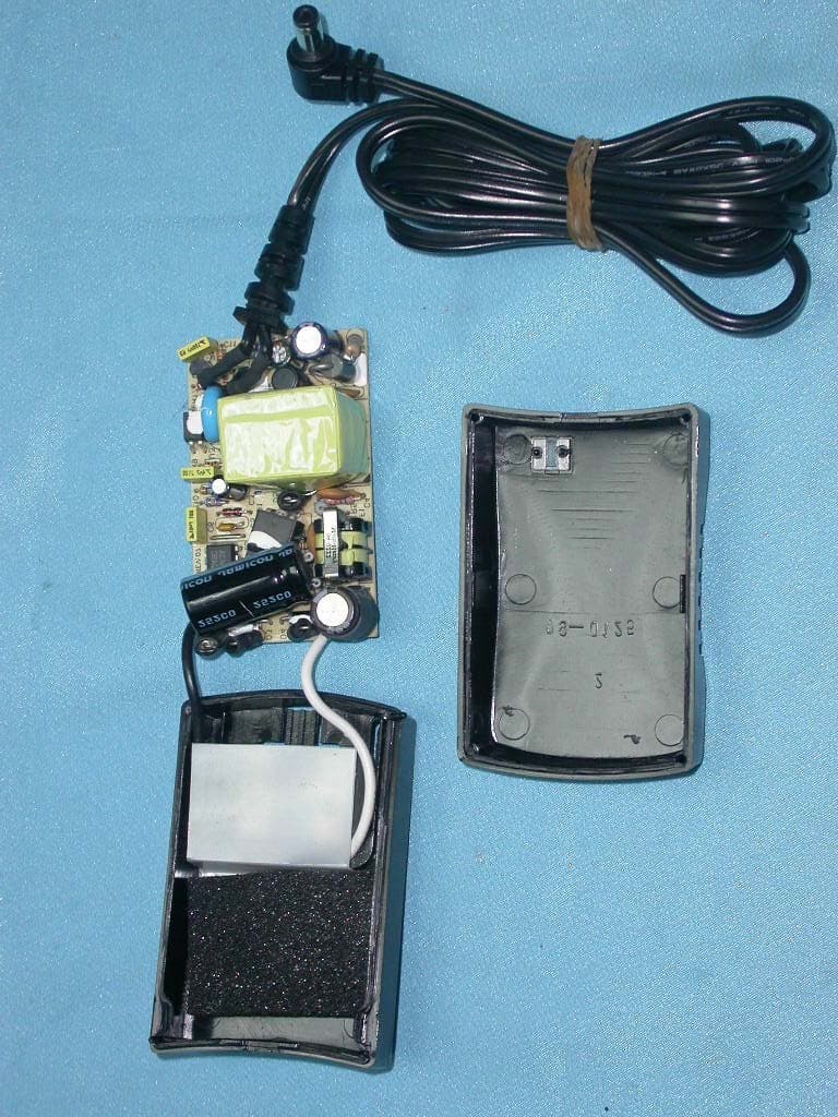
PKW-BEFW11S4V4
May 21, 2003Wireless Access Point Router
Equipment Class
DTS - Digital Transmission System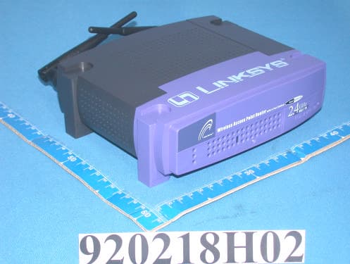
PKW-BEFW11S4V32
Apr 13, 2003Wireless Access Point Router with 4-Port Switch
Equipment Class
DTS - Digital Transmission System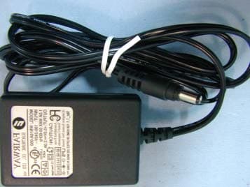
PKW-WSB24-2
Apr 03, 2003Wireless Signal Booster
Equipment Class
DTS - Digital Transmission System
PKW-BEFCMUH4
Apr 01, 2003Cable Gateway
Equipment Class
DTS - Digital Transmission System