PKW-WPC12WLAN Cardbus Card
Cisco-Linksys, LLC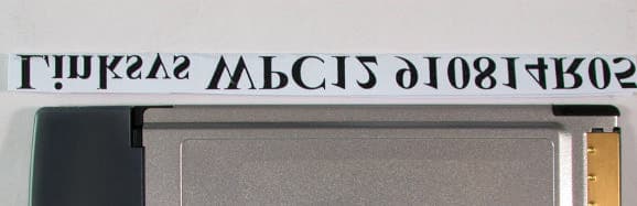
Click to zoom
Application Details
- Equipment Class
- DSS - Part 15 Spread Spectrum Transmitter
- Date of Grant
- Sep 23, 2002
- Application Purpose
- Original Equipment
- Date of Application
- Sep 23, 2002
- Equipment Note
- WLAN Cardbus Card
- Frequency Range
- 2412.00000000 - 2462.00000000
- Company
- Cisco-Linksys, LLC
- Country
- United States
Documents & Files
Document Text
Text extracted from the exhibit documents filed with the FCC. Open a document above to read the original.
Users Manual
2 • One I nstant Wireless T M N etwork PC C ard ver. 3.0 • One Setup U tility C D-R OM (U ser G uide on C D) • Quick I nstallation insert and R egistration C ard (not shown) • A 16-bit PC MC I A Type I Ior Type I I Islot • PC MC I A revisions 2.10 compliant card and socket services • Windows 95, 98, Millennium, NT, 2000, or X P • 600 K bytes of free disk space for utility and driver installation P a c k a g e C o n t e n t s S y s t e m R e q u i r e me n t s Instant Wireless TM Series 1 Chapter 1: Introduction Put the “ mobile” back into mobile computing! Whether you’ re at your desk or in the boardroom, the I nstant Wireless™ N etwork PC C ard allows you to share printers, files, and other resources anywhere within your L A N infrastructure, increasing your productivity and keeping you “ in touch.” T he I nstant Wireless™ N etwork PC C ard now has a new, higher-powered antenna that provides a greater range than ever. T he increased sensitivity helps filter out interference and “ noise” to keep your signal clear. I mproved error correction in the chipset keeps you operating at higher transmission rates for longer distances. A nd, since you only need one T ype I I or I I I PC MC I A slot, you’ re free to use your other slots for additional accessories. R eady to run in Type I I or I I I PC MC I A -equipped notebook PC s running Windows 95, 98, Millennium, N T , 2000, and XP, the I nstant Wireless™ N etwork PC C ard ver. 3.0 is truly a “ must-have” for all notebook PC users. •11 Mbps H igh-Speed Data T ransfer R ate •C ompatible with V irtually A ll Major N etwork Operating Systems •Plug-and-Play Operation Provides E asy Setup •I ntegrated E qualizer R ecovers Weak Signals and E nhances Sensitivity •Sturdy Metal Design with I ntegrated A ntenna •Works with A ll Standard I nternet A pplications •I nteroperable with I E E E 802.11b (DSSS) 2.4G H z-C ompliant E quipment •C lear C hannel A ssessment I ncreases N etwork T hroughput •H ardware B uffer C haining Provides H igh Performance While R eading and Writing B uffers •C apable of up to 128-B it WE P •F ree T echnical Support—24 H ours a Day, 7 Days a Week for N orth A merica Only •1-Year L imited Warranty F e a t u r e s T h e I n s t a n t Wi r e l e s s T M N e t wo r k P C C a r d v e r . 3 . 0 Network PC Card Figure 1-1 43 Chapter 3: Installing the Drivers and Configuration Utility for Windows 95, 98, ME, and 2000 Your new Linksys Instant Wireless™ Network PC Card ver. 3.0 comes with an automated software installation procedure for Windows 95, 98, Millennium, and 2000. Windows NTor XP users should refer to the next section.This new procedure automatically installs the drivers and Configuration Utility beforeyou insert the Card into your PC, so there’s no searching for the location of drivers. Again, this step is taken before inserting the Card into your PC. 1.Before installing your card, insert the Setup Utility CD into your CD-ROM drive. Unless you have deactivated the auto-run feature of Windows, the screen shown in Figure 2-1 should appear automati- cally. If this screen does not appear automatically, you can access the installation by clicking the Start button and choosing Run. In the drop-down box pro- vided, type D:\setup.exe(where D: is the letter of your CD-ROM drive). Alternately, double-click My Computerand double-click the CD-ROM drive where the Setup Utility CD is located. Double-click the Setup.exeicon in the folder that appears. Before You Start Running the Auto Driver Installation Network PC Card Chapter 2: Planning Your Wireless Network Awireless LAN is exactly like a regular LAN, except that each computer in the LAN uses an Instant Wireless™ Network PC Card ver. 3.0 to connect to the network through a wireless connection. Computers in a wireless LAN must be configured to share the same radio channel. The Instant Wireless™ Network PC Card ver. 3.0 provides LAN access for wireless workstations. An integrated wireless and wired LAN is called an Infrastructure configuration. A group of Instant Wireless™ Network PC Card ver. 3.0 users and an Access Point compose a Basic Service Set (BSS). Each PCequipped with an Instant Wireless™ Network PC Card ver. 3.0 in a BSS can talk to any computer in a wired LAN infrastructure via the Access Point. An infrastructure configuration extends the accessibility of an Instant Wireless™ Network PC Card ver. 3.0 PC to a wired LAN, and doubles the effective wireless transmission range for two PCs equipped with an Instant Wireless™ Network PC Card ver. 3.0. Since the Access Point is able to for- ward data within its BSS, the effective transmission range in an infrastructure LAN is doubled. Infrastructure mode also supports roaming capabilities for mobile users. More than one BSS can be configured as an Extended Service Set (ESS). This con- tinuous network allows users to roam freely within an ESS. All PCs, equipped with an Instant Wireless™ Network PC Card ver. 3.0, within one ESS must be configured with the same ESS ID. Before enabling an ESS with roaming capability, selecting a feasible radio channel and optimum Access Point position is recommended. Proper Access Point positioning combined with a clear radio signal will greatly enhance per- formance. Roaming Network Topology Figure 2-1 Instant Wireless TM Series
Users Manual
65 4.Figure 2-4 shows the Warranty Policyscreen. Read the entire policy by pressing the Page Downbutton on your keyboard or by using the on-screen scroll bar. Click on the Yesbutton if you agree, or Noif you disagree. Clicking Nowill terminate the installation. If you click Yes, the installation will continue. 5.The screen in Figure 2-5 will appear next, requesting the folder into which the Configuration Utility will be installed. To install the Configuration Utility in the default directo- ry (recom- mended), click the Nextbut- ton. If you prefer to install the Utility in another direc- tory, click the Browse button, and locate the preferred directory. Then, click the Next button. 2. The first tab across the top of the screen, labeled Install, should now be high- lighted. Click the Installbutton. A screen similar to that shown in Figure 2-2 should appear, indicating that Windows is preparing the installation. If, for whatever reason, you need to abort or terminate the installation, press the Cancelbutton at any time during the installation. Otherwise the instal- lation will continue automatically. 3. The screen in Figure 2-3 will appear next, indicating that Windows is ready to continue the installation. Click the Nextbutton. Note:If you stop the installation before it has finished, you will have to run the installation completely again before installing your hardware. Network PC Card Figure 2-2 Figure 2-3 Figure 2-4 Figure 2-5 Instant Wireless TM Series Unlike wired networks, wireless networks have two different modes in which they may be set up: Infrastructureand Ad-Hoc. Choosing between these two modes depends on whether or not the wireless network needs to share data or peripherals with a wired network or not. If the computers on the wireless network need to be accessible by a wired net- work or need to share a peripheral, such as a printer, with the wired network computers, the wireless network should be set up in the Infrastructure mode. The basis of Infrastructure mode centers around an access point, which serves as the main point of communications in a wireless network (see Figure 2-7). Access points transmit data to PCs equipped with wireless network cards, which can roam within a certain radial range of the access point. Multiple access points can be arranged to work in succession to extend the roam- ing range, and can be set up to com- municate with your Ethernet hardware as well. If the wireless network is relatively small and needs to share resources only with the other computers on the wireless network, then the Ad-Hoc mode can be used (shown in Figure 2-8). Ad-Hoc mode allows computers equipped with wireless Network PC Cards to communicate directly with each other, eliminat- ing the need for an access point. The drawback of this mode is in the fact that, in Ad-Hoc mode, wireless-equipped computers are not able to communicate with computers on a wired network. And, of course, communi- cation between the wireless-equipped computers is limited by the distance and interference directly between them. 87 Ad-Hoc versus Infrastructure Mode 6. When the screen shown in Figure 2-6 appears, choose either Infrastructure mode or Ad-Hocmode. If you are unsure whether to choose Infrastructure or Ad-Hoc, refer to the next section for more information. Once you have made your choice, click the Nextbutton. Network PC Card Figure 2-6 Figure 2-7 Figure 2-8 Instant Wireless TM Series 3.The screen shown in Figure 2-11 will appear, indicating that all of the appropriate files are being copied onto your drive. Click the Cancel button if you need to stop the installa- tion for any reason. 4. Once Windows has finished copying the necessary files, the screen shown in Figure 2-12 will appear. In order for the drivers to be installed properly, you must restart your computer. If you choose to do it now, select Yes, I want to restart my computer now. If you do not want to do it now, choose No, I will restart my computer later. Once you have made your choice, click the Finishbutton to continue. 10 1.If you have chosen Infrastructuremode, the following screen (Figure 2-9) will appear. If you have chosen Ad-Hocmode, skip to the next section, titled “Ad-Hoc Mode”. You will be prompted to enter an SSIDvalue in the box provided. The SSID may be up to 32 characters in length. This may include any character on the keyboard, keeping in mind that the SSID is case sensitive. All SSID values on your wireless network must match. If you are unsure, use the default value of “linksys.” Then, click the Nextbutton. 2. The Review Settings screen (Figure 2-10) will appear next. Verify that all the settings are correct and click the Nextbut- ton to continue. 9 Note:Restart the computer and go to Chapter 3: Installing the Network PCCardfor further instructions. Infrastructure Mode Figure 2-9 Figure 2-10 Figure 2-11 Figure 2-12 Instant Wireless TM Series Network PC Card 11 2. The screen shown in Figure 2-14 should appear. You will be prompted to enter an SSIDvalue in the field provided. All SSIDvalues on your wire- less network must match. If you are unsure, use the default value of “linksys.” Then, click the Nextbutton. 3. The next screen to appear (Figure 2-15) will be the Review Settings screen. Verify that all the settings are correct and click the Nextbutton to contin- ue. Network PC Card 1.If you have chosen Ad-Hoc mode, the following screen will appear. (See Figure 2-13.) If you have chosen Infrastructure mode, refer to the previ- ous section, titled “Infrastructure Mode”. You will be prompted to choose a Channelfrom the list provided. All computers on your wireless network must be using the same channel in order to communicate with each other. If you are unsure about which chan- nel to use, select the default channel (Channel 6). Once you have chosen your channel, click the Nextbutton. Ad-Hoc Mode Figure 2-13 Figure 2-14 Figure 2-15 Instant Wireless TM Series 12 Chapter 4: Installing the Drivers and Configuration Util…
Text truncated - open the document above for the full version.
Cover Letter(s)
Inform Letter Dear Customer, According to FCC’s regulation, the following Declaration of Conformity has to be made by a company located in USA. They are: This device has been confirmed to be in compliance with the requirements of ANSI C63.4 & FCC part 15 regulations. The test result has been shown in the ADT test report with number RF910814R04A. And this compliance is subject to the following two conditions: (1) This device may not cause harmful interference and, (2) This device must accept any interference received, including interference that may cause undesired operation. This declaration can be a separate sheet and be sure that the following message will be also included in this declaration: 1) Product name, model name and trade name. 2) Company name, and address of the one who is responsible for this declaration. 3) Name, title, telephone and fax number as well as the signature of the contact person. Thanks for your attention.
External Photos
Page 1 ANNEX PHOTOGRAPHS OF EUT Page 2
Internal Photos
Page 3 Page 4 Page 5
Operational Description
FCC ID: PKW-WPC12 ADT No.910814R05 Operational Description The transmitter of the EUT is powered by host equipment. The antenna is Chip antenna. There is no antenna connector. Under normal use condition, the user has to keep at least 2.5cm separation distance between radiator and the body of the user. The other instruction, please have a look at the users manual. DSSS Information This device is Direct Sequence Spread Spectrum, the data is mixed by pseudorandom code which is an orthogonal code. The mixed data is digital modulated by BPSK and QPSK technique depends on the data rates. The CCK coding is applied for increasing the data rate. The bit rates are 1,2,5.5,11,22Mbps, the symbol rates are 1,1,1.375,1.375,1.375 Mbps, the chip rates are always 11Mbps. So, the Chip/symbol is 11,11,8,8,and16 respectively. Although is higher bit rate, the processing gain is lower than 10, but the CCK coding used in higher bit rate will provide 2.2dB coding gain.
RF Exposure Info
Test Report S/N: 091002-278PKW Test Date(s): September 13, 2002 FCC SAR Evaluation © 2002 Celltech Research Inc.1 of 21 Celltech Research Inc. declares under its sole responsibility that this device was found to be in compliance with the Specific Absorption Rate (SAR) RF exposure requirements specified in FCC §2.1093 and was tested in accordance with the measurement standards and procedures specified in FCC OET Bulletin 65, Supplement C, Edition 01-01 (General Population / Uncontrolled Exposure). I attest to the accuracy of data. All measurements were performed by me or were made under my supervision and are correct to the best of my knowledge and belief. I assume full responsibility for the completeness of these measurements and vouch for the qualifications of all persons taking them. This test report shall not be reproduced partially, or in full, without the prior written approval of Celltech Research Inc. The results and statements contained in this report pertain only to the device(s) evaluated. Russell Pipe Senior Compliance Technologist Celltech Research Inc. DECLARATION OF COMPLIANCE SAR EVALUATION Test Lab CELLTECH RESEARCH INC. Testing and Engineering Lab 1955 Moss Court Kelowna, B.C. Canada V1Y 9L3 Phone: 250 - 860-3130 Fax: 250 - 860-3110 e-mail: [email protected] web site:www.celltechlabs.com Applicant Information THE LINKSYS GROUP INC. 17401 Armstrong Avenue Irvine, CA 92614 FCC Rule Part(s):§2.1093 Test Procedure(s):OET Bulletin 65, Supplement C (Edition 01-01) Device Classification:Part 15 Spread Spectrum Transmitter (DSS) FCC ID:PKW-WPC12 Model(s):WPC12 EUT Type:DSSS Wireless LAN PCMCIA Card for Laptop PC Tx Frequency Range:2412 - 2462 MHz Conducted Power Tested:17.99 dBm (2412 MHz) 17.54 dBm (2437 MHz) 16.87 dBm (2462 MHz) Antenna Type:Internal Power Supply:from host Laptop PC Max. SAR Measured:0.989 W/kg Test Report S/N: 091002-278PKW Test Date(s): September 13, 2002 FCC SAR Evaluation © 2002 Celltech Research Inc.2 of 21 TABLE OF CONTENTS 1.0INTRODUCTION..................................................................... 3 2.0DESCRIPTION OF EUT............................................................ 3 3.0SAR MEASUREMENT SYSTEM ............................................... 4 4.0MEASUREMENT SUMMARY..................................................... 5 5.0DETAILS OF SAR EVALUATION............................................... 6 6.0EVALUATION PROCEDURES................................................... 7 7.0SYSTEM VALIDATION............................................................. 8 8.0SIMULATED EQUIVALENT TISSUES......................................... 9 9.0SAR LIMITS........................................................................... 9 10.0SYSTEM SPECIFICATIONS......................................................10 11.0PROBE SPECIFICATION.........................................................11 12.0SAM PHANTOM......................................................................11 13.0DEVICE HOLDER.................................................................... 11 14.0TEST EQUIPMENT LIST...........................................................12 15.0MEASUREMENT UNCERTAINTIES............................................ 13 16.0REFERENCES........................................................................ 14 APPENDIX A - SAR MEASUREMENT DATA............................................. 15 APPENDIX B - SYSTEM VALIDATION.....................................................16 APPENDIX C - DIPOLE CALIBRATION...................................................17 APPENDIX D - PROBE CALIBRATION....................................................18 APPENDIX E - MEASURED FLUID DIELECTRIC PARAMETERS................19 APPENDIX F - SAM PHANTOM CERTIFICATE OF CONFORMITY..............20 APPENDIX G - SAR TEST SETUP & EUT PHOTOGRAPHS........................21 Test Report S/N: 091002-278PKW Test Date(s): September 13, 2002 FCC SAR Evaluation © 2002 Celltech Research Inc.THE LINKSYS GROUP INC. FCC ID: PKW-WPC123 of 21 DSSS WLAN PCMCIA Card for Laptop PC (2412-2462MHz) 1.0 INTRODUCTION This measurement report demonstrates that THE LINKSYS GROUP INC. Model: WPC12 DSSS Wireless LAN PCMCIA Card (for Laptop PC) FCC ID: PKW-WPC12 complies with the RF exposure requirements specified in FCC 47 CFR §2.1093 (see reference [1]). The test procedures described in FCC OET Bulletin 65, Supplement C, Edition 01-01 (see Reference [2]) were employed. A description of the product, operating configuration, detailed summary of the test results, methodology and procedures used in the evaluation, equipment used, and the various provisions of the rules are included within this test report. 2.0 DESCRIPTION of Equipment Under Test (EUT) FCC Rule Part(s) §2.1093 FCC Test Procedure OET Bulletin 65, Supplement C (Edition 01-01) FCC Device Classification Part 15 Spread Spectrum Transmitter (DSS) Device Type DSSS Wireless LAN PCMCIA Card (for Laptop PC) FCC ID PKW-WPC12 Model(s) WPC12 Serial No. Pre-production Tx Frequency Range 2412 - 2462 MHz RF Conducted Power Tested 17.99 dBm (2412 MHz) 17.54 dBm (2437 MHz) 16.87 dBm (2462 MHz) Antenna Type Internal Power Supply From host Laptop PC Test Report S/N: 091002-278PKW Test Date(s): September 13, 2002 FCC SAR Evaluation © 2002 Celltech Research Inc.THE LINKSYS GROUP INC. FCC ID: PKW-WPC124 of 21 DSSS WLAN PCMCIA Card for Laptop PC (2412-2462MHz) 3.0 SAR MEASUREMENT SYSTEM Celltech Research SAR measurement facility utilizes the Dosimetric Assessment System (DASY™) manufactured by Schmid & Partner Engineering AG (SPEAG™) of Zurich, Switzerland. The DASY system is comprised of the robot controller, computer, near-field probe, probe alignment sensor, specific anthropomorphic mannequin (SAM) phantom, and various planar phantoms for brain or body SAR evaluations. The robot is a six-axis industrial robot performing precise movements to position the probe to the location (points) of maximum electromagnetic field (EMF). A cell controller system c…
Text truncated - open the document above for the full version.
Test Report
FCC ID: PKW-WPC12 Report No.: RF910814R04A1Issued: August 30, 2002 FCC TEST REPORT REPORT NO.: RF910814R04A MODEL NO.: WPC12 RECEIVED: August 14, 2002 TESTED: July 16 ~ August 24, 2002 APPLICANT: The Linksys Group, INC. ADDRESS: 17401 Armstrong Ave. Irvine, CA 92614 ISSUED BY: Advance Data Technology Corporation LAB LOCATION: 47 14th Lin, Chiapau Tsun, Linko, Taipei, Taiwan, R.O.C. This test report consists of 50 pages in total. It may be duplicated completely for legal use with the approval of the applicant. It should not be reproduced except in full, without the written approval of our laboratory. The client should not use it to claim product endorsement by CNLA, NVLAP or any government agencies. The test results in the report only apply to the tested sample. 0528 ILAC MRA Lab Code: 200102-0 FCC ID: PKW-WPC12 Report No.: RF910814R04A2Issued: August 30, 2002 Table of Contents 1CERTIFICATION ........................................................................................... 4 2SUMMARY OF TEST RESULTS................................................................... 5 3GENERAL INFORMATION ........................................................................... 6 3.1GENERAL DESCRIPTION OF EUT.............................................................. 6 3.2DESCRIPTION OF TEST MODES................................................................ 7 3.3GENERAL DESCRIPTION OF APPLIED STANDARDS ............................... 7 3.4DESCRIPTION OF SUPPORT UNITS .......................................................... 8 4TEST TYPES AND RESULTS....................................................................... 9 4.1CONDUCTED EMISSION MEASUREMENT ................................................ 9 4.1.1LIMITS OF CONDUCTED EMISSION MEASUREMENT.............................. 9 4.1.2TEST INSTRUMENTS .................................................................................. 9 4.1.3TEST PROCEDURES................................................................................. 10 4.1.4DEVIATION FROM TEST STANDARD ....................................................... 10 4.1.5TEST SETUP ...............................................................................................11 4.1.6EUT OPERATING CONDITIONS................................................................ 12 4.1.7TEST RESULTS.......................................................................................... 13 4.2RADIATED EMISSION MEASUREMENT ................................................... 19 4.2.1LIMITS OF RADIATED EMISSION MEASUREMENT................................. 19 4.2.2TEST INSTRUMENTS ................................................................................ 20 4.2.3TEST PROCEDURES................................................................................. 21 4.2.4DEVIATION FROM TEST STANDARD ....................................................... 21 4.2.5TEST SETUP .............................................................................................. 22 4.2.6EUT OPERATING CONDITIONS................................................................ 22 4.2.7TEST RESULTS.......................................................................................... 23 4.36dB BANDWIDTH MEASUREMENT .......................................................... 28 4.3.1LIMITS OF 6dB BANDWIDTH MEASUREMENT ........................................ 28 4.3.2TEST INSTRUMENTS ................................................................................ 28 4.3.3TEST PROCEDURE ................................................................................... 29 4.3.4DEVIATION FROM TEST STANDARD ....................................................... 29 4.3.5TEST SETUP .............................................................................................. 29 4.3.6EUT OPERATING CONDITIONS................................................................ 29 4.3.7TEST RESULTS.......................................................................................... 30 4.4MAXIMUM PEAK OUTPUT POWER .......................................................... 34 4.4.1LIMITS OF MAXIMUM PEAK OUTPUT POWER MEASUREMENT ........... 34 4.4.2TEST INSTRUMENTS ................................................................................ 34 FCC ID: PKW-WPC12 Report No.: RF910814R04A3Issued: August 30, 2002 4.4.3TEST PROCEDURES................................................................................. 35 4.4.4DEVIATION FROM TEST STANDARD ....................................................... 35 4.4.5TEST SETUP .............................................................................................. 35 4.4.6EUT OPERATING CONDITIONS................................................................ 35 4.4.7TEST RESULTS.......................................................................................... 36 4.5POWER SPECTRAL DENSITY MEASUREMENT...................................... 37 4.5.1LIMITS OF POWER SPECTRAL DENSITY MEASUREMENT ................... 37 4.5.2TEST INSTRUMENTS ................................................................................ 37 4.5.3TEST PROCEDURE ................................................................................... 38 4.5.4DEVIATION FROM TEST STANDARD....................................................... 38 4.5.5TEST SETUP .............................................................................................. 38 4.5.6EUT OPERATING CONDITIONS................................................................ 38 4.5.7TEST RESULTS.......................................................................................... 39 4.6BAND EDGES MEASUREMENT ................................................................ 43 4.6.1LIMITS OF BAND EDGES MEASUREMENT ............................................. 43 4.6.2TEST INSTRUMENTS ................................................................................ 43 4.6.3TEST PROCEDURE ........................…
Text truncated - open the document above for the full version.
Contact Information
Applicant
Ms Jennifer Yu(Associate Engineer)
Technical Contact
Advance Data Technology CorporationVivi Wang
[email protected]+886 3 327 0910
13-1, Lane 19, WenShan 3rd St · Taoyuan · Taiwan
Test Firm
Bureau Veritas CPS (H.K.) Ltd. Taoyuan BranchRichard Chen
Technical Specifications
| # | Rule Parts | Frequency Range | Power Output |
|---|---|---|---|
| 1 | 15C | 2.41 GHz - 2.46 GHz | 63.00 mW |
Other Applications from Cisco-Linksys, LLC

PKW-WMP54GV2
May 29, 2003Wireless-G PCI Adapter
Equipment Class
DTS - Digital Transmission System
PKW-BEFW11S4V4
May 21, 2003Wireless Access Point Router
Equipment Class
DTS - Digital Transmission System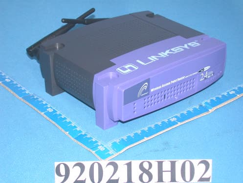
PKW-BEFW11S4V32
Apr 13, 2003Wireless Access Point Router with 4-Port Switch
Equipment Class
DTS - Digital Transmission System
PKW-WSB24-2
Apr 03, 2003Wireless Signal Booster
Equipment Class
DTS - Digital Transmission System
PKW-BEFCMUH4
Apr 01, 2003Cable Gateway
Equipment Class
DTS - Digital Transmission System