PKW-WPC54GWireless 802.11g Notebook Adapter
Cisco-Linksys, LLC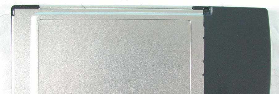
Click to zoom
Application Details
- Equipment Class
- DTS - Digital Transmission System
- Date of Grant
- Dec 12, 2002
- Application Purpose
- Original Equipment
- Date of Application
- Dec 12, 2002
- Equipment Note
- Wireless 802.11g Notebook Adapter
- Frequency Range
- 2412.00000000 - 2462.00000000
- Company
- Cisco-Linksys, LLC
- Country
- United States
Documents & Files
Document Text
Text extracted from the exhibit documents filed with the FCC. Open a document above to read the original.
Users Manual
Instant Wireless ® Series User Guide Wireless-GNotebook AdapterUse this Guide to install the following:WPC54G COPYRIGHT & TRADEMARKS Specifications are subject to change without notice. Copyright © 2003 Linksys, All RightsReserved. Instant Wireless, Linksys, and the Linksys logo are registered trademarks ofLinksys Group, Inc. Microsoft, Windows, and the Windows logo are registered trade-marks of Microsoft Corporation. All other trademarks and brand names are the proper-ty of their respective proprietors. LIMITED WARRANTY Linksys guarantees that every Instant Wireless ® Wireless-G Notebook Adapter will be free from physical defects in material and workmanship for one year from the date of pur-chase, when used within the limits set forth in the Specifications section of this UserGuide. If the product proves defective during this warranty period, call Linksys TechnicalSupport in order to obtain a Return Authorization number. BE SURE TO HAVE YOURPROOF OF PURCHASE ON HAND WHEN CALLING. When returning a product, markthe Return Authorization number clearly on the outside of the package and include acopy of your original proof of purchase. RETURN REQUESTS CANNOT BE PROCESSEDWITHOUT PROOF OF PURCHASE. All customers located outside of the United Statesof America and Canada shall be held responsible for shipping and handling charges.IN NO EVENT SHALL LINKSYS'S LIABILITY EXCEED THE PRICE PAID FOR THE PROD-UCT FROM DIRECT, INDIRECT, SPECIAL, INCIDENTAL, OR CONSEQUENTIAL DAM-AGES RESULTING FROM THE USE OF THE PRODUCT, ITS ACCOMPANYING SOFT-WARE, OR ITS DOCUMENTATION. LINKSYS OFFERS NO REFUNDS FOR ITS PROD-UCTS. Linksys makes no warranty or representation, expressed, implied, or statutory,with respect to its products or the contents or use of this documentation and all accom-panying software, and specifically disclaims its quality, performance, merchantability, orfitness for any particular purpose. Linksys reserves the right to revise or update its prod-ucts, software, or documentation without obligation to notify any individual or entity.Please direct all inquiries to:Linksys P.O. Box 18558, Irvine, CA 92623. SAFETY AND REGULATORY NOTICESFCC STATEMENTThe Instant Wireless ® Wireless-G Notebook Adapter has been tested and found to com- ply with the specifications for a Class B digital device, pursuant to Part 15 of the FCCRules. Operation is subject to the following two conditions: (1) This device may not cause harmful interference, and (2) This device must accept any interference received, including interference that may cause undesired operation. These limits are designed to provide reasonable protection against harmful interferencein a residential installation. This equipment generates, uses, and can radiate radio fre-quency energy and, if not installed and used according to the instructions, may causeharmful interference to radio communications. However, there is no guarantee that inter-ference will not occur in a particular installation. If this equipment does cause harmfulinterference to radio or television reception, which is found by turning the equipment offand on, the user is encouraged to try to correct the interference by one or more of thefollowing measures: • Reorient or relocate the receiving antenna • Increase the separation between the equipment or devices • Connect the equipment to an outlet other than the receiver's • Consult a dealer or an experienced radio/TV technician for assistance FCC Caution: Any change or modification to the product not expressly approved byLinksys could void the user's authority to operate the device.FCC RF Radiation Exposure StatementTo comply with the FCC and ANSI C95.1 RF exposure limits, the antenna(s) for thisdevice must comply with the following:• Access points with 2.4 GHz or 5 GHz integrated antenna must operate with a sepa-ration distance of at least 20 cm from all persons using the cable provided and mustnot be co-located or operating in conjunction with any other antenna or transmitter. End-users must be provided with specific operations for satisfying RF exposure compli-ance.Note: Dual antennas used for diversity operation are not considered co-located.Canadian Department of Communications Industry Canada (IC) NoticeThis Class B digital apparatus complies with Canadian ICES-003 and RSS-210.Cet appareil numérique de la classe B est conforme à la norme NMB-003 et CNR-210du Canada."To prevent radio interference to the licensed service, this device is intended to be oper-ated indoors and away from windows to provide maximum shielding. Equipment (or itstransmit antenna) that is installed outdoors is subject to licensing."" Pour empêcher que cet appareil cause du brouillage au service faisant l'objet d'unelicence, il doit être utilisé à l'intérieur et devrait être placé loin des fenêtres afin de fournirun écran de blindage maximal. Si le matériel (ou son antenne d'émission) est installé àl'extérieur, il doit faire l'objet d'une licence. "EC DECLARATION OF CONFORMITY (EUROPE)Linksys Group declares that the Instant Wireless ® Series products included in the Instant Wireless ® Series conform to the specifications listed below, following the provisions of the European R&TTE directive 1999/5/EC, EMC directive 89/336/EEC, and Low Voltagedirective 73/23/EEC: For 11Mpbs, 2.4 GHz devices with 100 mW radios, the following standards were applied: • ETS 300-826, 301 489-1 General EMC requirements for Radio equipment. • EN 609 50 Safety • ETS 300-328-2 Technical requirements for Radio equipment. Caution: This equipment is intended to be used in all EU and EFTA countries. Outdooruse may be restricted to certain frequencies and/or may require a license for operation.Contact local Authority for procedure to follow. Note: Combinations of power levels and antennas resulting in a radiated power level ofabove 100 mW equivalent isotropic radiated power (EIRP) are considered as not com-pliant with the above mentioned directive and are not allowed for use within the Europeanc…
Text truncated - open the document above for the full version.
Users Manual
Wireless-G Notebook Adapter 17 Instant Wireless ® Series The Link Information screen displays signal strength and link quality informa- tion about the current connection and provides a button to click for additionalstatus information. Ad-Hoc Mode or Infrastructure Mode - The screen indicates whether the Adapter is currently working in ad-hoc or infrastructure mode. Signal Strength - The Signal Strength bar indicates signal strength, from 0 to 100%. Link Quality - The Link Quality bar indicates the quality of the wireless net- work connection, from 0 to 100%.Click the More Information button to view more information about the wire- less network connection.Click the X (Close) button in the upper right corner to exit the WLAN Monitor. 16 TCP/IP SettingIP Address - The IP Address of the Adapter. Subnet Mask - The Subnet Mask of the Adapter. Default Gateway - The Default Gateway address of the Adapter. DHCP - The status of the DHCP client. DNS - The DNS address of the Adapter. Wireless Network StatusState - The status of the wireless network connection. SSID - The unique name of the wireless network. Wireless Mode - The mode of the wireless network currently in use. Transfer Rate - The data transfer rate of the current connection. Channel - The channel to which the wireless network devices are set. WEP - The status of the WEP encryption security feature. MAC - The MAC address of the wireless network’s access point. Signal Strength - The Signal Strength bar indicates signal strength, from 0 to 100%. Link Quality - The Link Quality bar indicates the quality of the wireless net- work connection, from 0 to 100%.Click the Back button to return to the initial Link Information screen. Click the X (Close) button in the upper right corner to exit the WLAN Monitor. Figure 7-4 Link Information Figure 7-3 Wireless-G Notebook AdapterIn the WEP drop-down box, select the type of WEP encryption used by the wireless network: 64-bit , or 128-bit WEP. If the wireless network uses a passphrase, enter the passphrase in thePassphrase field. If the wireless network uses a WEP key, enter the WEP key in the Key 1 field. Click the OK button to complete the network connection and return to the Site Survey screen, or click the Cancel button to cancel the network connection and return to the Site Survey screen. On the Site Survey screen, click the X (Close) button in the upper right corner to exit the WLAN Monitor. 19 Instant Wireless ® Series 18 Figure 7-6 The Site Survey screen displays a list of infrastructure and ad-hoc networks available for connection. SSID - The SSID or unique name of the wireless network. Signal - The percentage of signal strength, from 0 to 100%. Site InformationWireless Mode - The mode of the wireless network currently in use. Channel - The channel to which the wireless network devices are set. WEP - The status of the WEP encryption security feature. MAC - The MAC address of the wireless network’s access point. Surveyed at - The time at which the wireless network was scanned. Refresh - Click the Refresh button to perform a new search for wireless devices. Connect - To connect to one of the networks on the list, select the wireless net- work , and click the Connect button. If the wireless network has WEP encryp- tion enabled, you will see the screen shown in Figure 7-6. Figure 7-5 Site Survey Wireless-G Notebook Adapter 21 Instant Wireless ® Series 20 Import - Click the Import button to import a profile that has been saved in another location. Select the appropriate file, and click the Open button. Export - To save the profile(s) in a different location, click the Export button. Direct Windows to the appropriate folder, and click the OK button. Delete - Click the Delete button to delete a profile. Click the X (Close) button in the upper right corner to exit the WLAN Monitor. Figure 7-8Figure 7-9 Note: If you have more than one profile, all profiles will be auto- matically selected and exported to the same folder. The Profiles screen lets you save different configuration profiles for different network setups. You can also import or export profiles. The default profileholds the initial configuration saved when you ran the Setup Wizard.Profile - Name of the connection profile. SSID - The wireless network’s unique name, as set in the connection profile. Profile InformationNetwork Type - The mode of the wireless network currently in use. Transfer Rate - The data transfer rate of the current connection. (In Auto mode, the Adapter dynamically shifts to the fastest data transfer rate possibleat any given time.)Channel - The channel to which the wireless network devices are set. WEP - The status of the WEP encryption security feature. Connect - To connect to a wireless network using a specific profile, select the profile , and click the Connect button. Edit - Select a profile, and click the Edit button to change an existing profile. New - Click the New button to create a new profile. See the next section, “Creating a New Profile,” for detailed instructions. Figure 7-7 Profiles Wireless-G Notebook Adapter2. The Choose a network type screen shows a choice of two wireless modes. Click the Infrastructure Mode radio button if you want your wireless computers to communicate with computers on your wired network via awireless access point. Click the Ad-Hoc Mode radio button if you want multiple wireless computers to communicate directly with each other. Clickthe Next button to continue or the Back button to return to the previous screen.Infrastructure Mode - This mode allows wireless and wired networks to communicate through an access point.Ad-Hoc Mode - This mode allows wireless-equipped computers to com- municate directly with each other. No access point is used. 23 Instant Wireless ® Series 1. On the Profiles screen, click the New button to create a new profile. 2. When the Create connection profile screen appears, enter a name for the new profile. Click OK to save the profile name or click Cancel to return t…
Text truncated - open the document above for the full version.
External Photos
Page 1 ANNEX PHOTOGRAPHS OF EUT Page 2
Internal Photos
Page 3 Page 4 Page 5
Operational Description
FCC ID: PKW-WPC54G ADT No.911210R03 Operational Description This device is a Instant Wireless Wireless-G Notebook Adapter which operates in 2.4GHz band, the maximum data rate could be up to 54Mbps which OFDM technique will be applied. If the signal to noise radio is too poor which could not support 54Mbps, the 11Mbps data rate with CCK technique will be applied. The transmitter of the EUT is powered by host equipment via a PCMCIA interface. The antenna is Chip antenna. There is no antenna connector. The other instruction, please have a look at the users manual.
RF Exposure Info
FCC ID: PKW-WPC54G Report No.: SA911203R02A1Issued: Dec. 11, 2002 SAR TEST REPORT REPORT NO.: SA911203R02A MODEL NO.: WPC54G RECEIVED: Dec. 10, 2002 TESTED: Dec. 06, 2002 APPLICANT: The Linksys Group, Inc. ADDRESS: 17401 Armstrong Ave. Irvine, CA 92614 ISSUED BY: Advance Data Technology Corporation LAB LOCATION: 47 14th Lin, Chiapau Tsun, Linko, Taipei, Taiwan, R.O.C. This test report consists of 13 pages in total except Appendix. It may be duplicated completely for legal use with the approval of the applicant. It should not be reproduced except in full, without the written approval of our laboratory. The client should not use it to claim product endorsement by CNLA, NVLAP or any government agencies. The test results in the report only apply to the tested sample. FCC ID: PKW-WPC54G Report No.: SA911203R02A2Issued: Dec. 11, 2002 Table of Contents 1.CERTIFICATION ........................................................................................... 3 2.GENERAL INFORMATION ........................................................................... 4 2.1GENERAL DESCRIPTION OF EUT.............................................................. 4 2.2GENERAL DESCRIPTION OF APPLIED STANDARDS ............................... 4 3.DESCRIPTION OF TEST MODES AND CONFIGURATIONS ...................... 5 4.DESCRIPTION OF SUPPORT UNITS .......................................................... 6 5.TEST RESULTS............................................................................................ 7 5.1TEST PROCEDURES................................................................................... 7 5.2MEASURED SAR RESULT........................................................................... 7 5.3SAR LIMITS .................................................................................................. 8 5.4EUT CONDUCTED POWER VARIATION ..................................................... 8 5.5TISSUE ......................................................................................................... 9 5.6TEST EQUIPMENT....................................................................................... 9 6.SYSTEM VALIDATION................................................................................ 10 7.MEASUREMENT UNCERTAINTIES ............................................................11 8.INFORMATION ON THE TESTING LABORATORIES ................................ 13 APPENDIX A: TEST CONFIGURATIONS AND TEST DATA APPENDIX B: ADT SAR MEASUREMENT SYSTEM APPENDIX C: PHOTOGRAPHS OF SYSTEM VALIDATION APPENDIX D: SYSTEM CERTIFICATE & CALIBRATION FCC ID: PKW-WPC54G Report No.: SA911203R02A3Issued: Dec. 11, 2002 1. CERTIFICATION PRODUCT : Instant Wireless Wireless-G Notebook Adapter MODEL NO. : WPC54G BRAND : Linksys APPLICANT : The Linksys Group, Inc. STANDARDS : 47 CFR Part 2 (Section 2.1093), FCC OET Bulletin 65, Supplement C (01-01) We, Advance Data Technology Corporation, hereby certify that one sample of the designation has been tested in our facility on 6 th Dec. 2002. The test record, data evaluation and Equipment Under Test (EUT) configurations represented herein are true and accurate accounts for the measurements of the sample's EMC characteristics under the conditions herein specified. FCC ID: PKW-WPC54G Report No.: SA911203R02A4Issued: Dec. 11, 2002 2. GENERAL INFORMATION 2.1 GENERAL DESCRIPTION OF EUT PRODUCT Instant Wireless Wireless-G Notebook Adapter MODEL NO. WPC54G POWER SUPPLY 3.3VDC powered by host MODULATION TYPE DBPSK, QPSK, CCK, 16QAM, 64QAM RADIO TECHNOLOGY DSSS, OFDM TRANSFER RATE 1/2/5.5/11Mbps FREQUENCY RANGE 2412MHz ~ 2462MHz NUMBER OF CHANNEL 11 CONDUCTED OUTPUT POWER 15.24 dBm (33.42mW) ANTENNA TYPE Chip antenna PEAK SAR 0.516 W/kg DATA CABLE NA I/O PORTS PCMCIA ASSOCIATED DEVICES NA 2.2 GENERAL DESCRIPTION OF APPLIED STANDARDS According to the specifications of the manufacturer, this product must comply with the requirements of the following standards: FCC CFR 47 Part 2 (2.1093) FCC OET Bulletin 65, Supplement C (01- 01) All tests have been performed and recorded as per the above standards. FCC ID: PKW-WPC54G Report No.: SA911203R02A5Issued: Dec. 11, 2002 3. DESCRIPTION OF TEST MODES AND CONFIGURATIONS CARRIER MODULATION UNDER TEST Un-modulated CW Carrier CREST FACTOR 1.0 CHANNEL FREQUENCIES UNDER TEST AND ITS CONDUCTED OUTPUT POWER Ch. 1: 2412MHz / 15.12 dBm Ch. 6: 2437MHz / 15.24 dBm Ch. 11: 2462MHz / 15.14 dBm ANTENNA CONFIGURATION Chip EUT POWER SOURCE From Host Notebook HOST POWER SOURCE Fully Charged Battery The following test configurations have been applied in this test report: Mode 1: EUT in the top PCMCIA slot of the notebook, the keyboard face of the notebook contact the bottom of the flat phantom with 0 cm separation distance. Mode 2: EUT in the bottom PCMCIA slot of the notebook, the bottom of the notebook contact the bottom of the flat phantom with 0 cm separation distance. Mode 3: EUT in the bottom PCMCIA slot of the notebook, the keyboard face of the notebook is perpendicular to the bottom of the flat phantom and the EUT is located between notebook and phantom. The separation distance is 0 cm between the tip of the EUT and the bottom of the flat phantom. Note 1: Please reference “APPENDIX A” for the photos of test configuration. Note 2: The output power of the un-modulated CW carrier has been adjusted to be the same with that of modulated signal. FCC ID: PKW-WPC54G Report No.: SA911203R02A6Issued: Dec. 11, 2002 4. DESCRIPTION OF SUPPORT UNITS The EUT has been tested as an independent unit together with other necessary accessories or support units. The following support units or accessories were used to form a representative test configuration during the tests. NO.PRODUCTBRANDMODEL NO.SERIAL NO.FCC ID 1NOTEBOOKDELLPP01LTW-09C748-12800-19O- B220 FCC DoC APPROVED NO.SIGNAL CABLE DESCRIPTION OF THE ABOVE SUPPORT UNITS 1NA NOTE: All power cords of the above support units are non shielded (1.8m). FCC ID: PKW-WPC54G Report No.: SA911203R02A7Issued: …
Text truncated - open the document above for the full version.
Test Report
FCC ID: PKW-WPC54G Report No.: RF911203R02A1Issued: December 11, 2002 FCC TEST REPORT REPORT NO.: RF911203R02A MODEL NO.: WPC54G RECEIVED: Dec. 10, 2002 TESTED: Dec. 2 ~ Dec. 4, 2002 APPLICANT: The Linksys Group, Inc. ADDRESS: 17401 Armstrong Ave. Irvine, CA 92614 ISSUED BY: Advance Data Technology Corporation LAB LOCATION: 47 14th Lin, Chiapau Tsun, Linko, Taipei, Taiwan, R.O.C. This test report consists of 64 pages in total. It may be duplicated completely for legal use with the approval of the applicant. It should not be reproduced except in full, without the written approval of our laboratory. The client should not use it to claim product endorsement by CNLA, NVLAP or any government agencies. The test results in the report only apply to the tested sample. 0528 ILAC MRA Lab Code: 200102-0 FCC ID: PKW-WPC54G Report No.: RF911203R02A2Issued: December 11, 2002 Table of Contents 1CERTIFICATION ........................................................................................... 4 2SUMMARY OF TEST RESULTS................................................................... 5 3GENERAL INFORMATION ........................................................................... 6 3.1GENERAL DESCRIPTION OF EUT.............................................................. 6 3.2DESCRIPTION OF TEST MODES................................................................ 7 3.3GENERAL DESCRIPTION OF APPLIED STANDARDS ............................... 7 3.4DESCRIPTION OF SUPPORT UNITS .......................................................... 8 4TEST TYPES AND RESULTS....................................................................... 9 4.1CONDUCTED EMISSION MEASUREMENT ................................................ 9 4.1.1LIMITS OF CONDUCTED EMISSION MEASUREMENT.............................. 9 4.1.2TEST INSTRUMENTS .................................................................................. 9 4.1.3TEST PROCEDURES................................................................................. 10 4.1.4DEVIATION FROM TEST STANDARD ....................................................... 10 4.1.5TEST SETUP ...............................................................................................11 4.1.6EUT OPERATING CONDITIONS................................................................ 12 4.1.7TEST RESULTS.......................................................................................... 13 4.2RADIATED EMISSION MEASUREMENT ................................................... 19 4.2.1LIMITS OF RADIATED EMISSION MEASUREMENT................................. 19 4.2.2TEST INSTRUMENTS ................................................................................ 20 4.2.3TEST PROCEDURES................................................................................. 21 4.2.4DEVIATION FROM TEST STANDARD ....................................................... 21 4.2.5TEST SETUP .............................................................................................. 22 4.2.6EUT OPERATING CONDITIONS................................................................ 22 4.2.7TEST RESULTS.......................................................................................... 23 4.2.8TEST RESULTS (A) .................................................................................... 25 4.2.9TEST RESULTS (B) .................................................................................... 28 4.36dB BANDWIDTH MEASUREMENT .......................................................... 31 4.3.1LIMITS OF 6dB BANDWIDTH MEASUREMENT ........................................ 31 4.3.2TEST INSTRUMENTS ................................................................................ 31 4.3.3TEST PROCEDURE ................................................................................... 32 4.3.4DEVIATION FROM TEST STANDARD ....................................................... 32 4.3.5TEST SETUP .............................................................................................. 32 4.3.6EUT OPERATING CONDITIONS................................................................ 32 4.3.7TEST RESULTS (A) .................................................................................... 33 4.3.8TEST RESULTS (B) .................................................................................... 37 FCC ID: PKW-WPC54G Report No.: RF911203R02A3Issued: December 11, 2002 4.4MAXIMUM PEAK OUTPUT POWER .......................................................... 41 4.4.1LIMITS OF MAXIMUM PEAK OUTPUT POWER MEASUREMENT ........... 41 4.4.2TEST INSTRUMENTS ................................................................................ 41 4.4.3TEST PROCEDURES................................................................................. 42 4.4.4DEVIATION FROM TEST STANDARD ....................................................... 42 4.4.5TEST SETUP .............................................................................................. 42 4.4.6EUT OPERATING CONDITIONS................................................................ 42 4.4.7TEST RESULTS (A) .................................................................................... 43 4.4.8TEST RESULTS (B) .................................................................................... 43 4.5POWER SPECTRAL DENSITY MEASUREMENT...................................... 44 4.5.1LIMITS OF POWER SPECTRAL DENSITY MEASUREMENT ................... 44 4.5.2TEST INSTRUMENTS ................................................................................ 44 4.5.3TEST PROCEDURE ................................................................................... 45 4.5.4DEVIATION FROM TEST STANDARD ....................................................... 45 4.5.5TEST SETUP .............................................................................................. 45 4.5.6EUT OPERATING CONDITIONS................................................................ 45…
Text truncated - open the document above for the full version.
Test Setup Photos
FCC ID: PKW-WPC54G Report No.: RF911203R02A62Issued: December 11, 2002 5 PHOTOGRAPHS OF THE TEST CONFIGURATION CONDUCTED EMISSION TEST FCC ID: PKW-WPC54G Report No.: RF911203R02A63Issued: December 11, 2002 RADIATED EMISSION TEST
Contact Information
Applicant
Ms Jennifer Yu(Associate Engineer)
Technical Contact
Advance Data Technology CorporationEllis Wu
[email protected]+886 3 327 0910
13-1, Lane 19, WenShan 3rd St · Taoyuan · Taiwan
Test Firm
Bureau Veritas CPS (H.K.) Ltd. Taoyuan BranchRichard Chen
Technical Specifications
| # | Rule Parts | Frequency Range | Power Output |
|---|---|---|---|
| 1 | 15C | 2.41 GHz - 2.46 GHz | 33.00 mW |
Other Applications from Cisco-Linksys, LLC

PKW-WMP54GV2
May 29, 2003Wireless-G PCI Adapter
Equipment Class
DTS - Digital Transmission System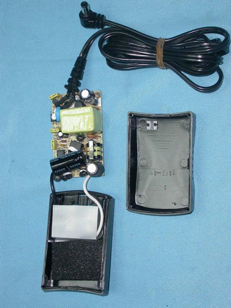
PKW-BEFW11S4V4
May 21, 2003Wireless Access Point Router
Equipment Class
DTS - Digital Transmission System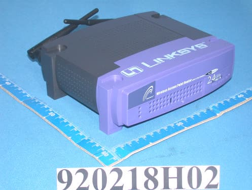
PKW-BEFW11S4V32
Apr 13, 2003Wireless Access Point Router with 4-Port Switch
Equipment Class
DTS - Digital Transmission System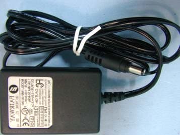
PKW-WSB24-2
Apr 03, 2003Wireless Signal Booster
Equipment Class
DTS - Digital Transmission System
PKW-BEFCMUH4
Apr 01, 2003Cable Gateway
Equipment Class
DTS - Digital Transmission System