PKW-WPG11Wireless Presentation Gateway
Cisco-Linksys, LLC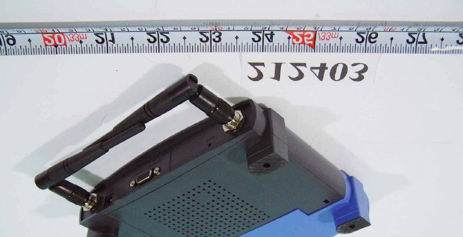
Click to zoom
Application Details
- Equipment Class
- DTS - Digital Transmission System
- Date of Grant
- Jul 11, 2002
- Application Purpose
- Original Equipment
- Date of Application
- Jul 11, 2002
- Equipment Note
- Wireless Presentation Gateway
- Frequency Range
- 2412.00000000 - 2462.00000000
- Company
- Cisco-Linksys, LLC
- Country
- United States
Documents & Files
Document Text
Text extracted from the exhibit documents filed with the FCC. Open a document above to read the original.
Users Manual
THE LINKSYS GROUP, INC. 17401 Armstrong Ave., Irvine, CA 92614 TEL: (949) 261-1288 FAX: (949) 261-8868 Wireless Presentation Gateway WPG11 User’s Manual FCC ID:PKW-WPG11 Draft 2.0 – Apr. 2002 2 Copyright statement No part of this publication may be reproduced, stored in a retrieval system, or transmitted in any form or by any means, whether electronic, mechanical, photocopying, recording, or otherwise without the prior written consent of the publisher. Printed in Taiwan, April 2002 3 IMPORTANT INFORMATION Federal Communication Commission Interference Statement This equipment has been tested and found to comply with the limits for a Class B digital device, pursuant to Part 15 of the FCC Rules. These limits are designed to provide reasonable protection against harmful interference in a residential installation. This equipment generates, uses and can radiate radio frequency energy and, if not installed and used in accordance with the instructions, may cause harmful interference to radio communications. However, there is no guarantee that interference will not occur in a particular installation. If this equipment does cause harmful interference to radio or television reception, which can be determined by turning the equipment off and on, the user is encouraged to try to correct the interference by one of the following measures: - Reorient or relocate the receiving antenna. - Increase the separation between the equipment and receiver. - Connect the equipment into an outlet on a circuit different from that to which the receiver is connected. - Consult the dealer or an experienced radio/TV technician for help. FCC Caution: To assure continued compliance, (example - use only shielded interface cables when connecting to computer or peripheral devices). Any changes or modifications not expressly approved by the party responsible for compliance could void the user's authority to operate this equipment. This device complies with Part 15 of the FCC Rules. Operation is subject to the following two conditions: (1) This device may not cause harmful interference, and (2) this device must accept any interference received, including interference that may cause undesired operation. IMPORTANT NOTE: FCC RF Radiation Exposure Statement: This equipment complies with FCC RF radiation exposure limits set forth for an uncontrolled environment. This equipment should be installed and operated with a minimum distance of 20 centimeters between the radiator and your body. This transmitter must not be co-located or operating in conjunction with any other antenna or transmitter. 4 R&TTE Compliance Statement This equipment complies with all the requirements of the DIRECTIVE 1999/5/EC OF THE EUROPEAN PARLIAMENT AND THE COUNCIL of 9 March 1999 on radio equipment and telecommunication terminal Equipment and the mutual recognition of their conformity (R&TTE). The R&TTE Directive repeals and replaces in the directive 98/13/EEC (Telecommunications Terminal Equipment and Satellite Earth Station Equipment) As of April 8, 2000. Safety This equipment is designed with the utmost care for the safety of those who install and use it. However, special attention must be paid to the dangers of electric shock and static electricity when working with electrical equipment. All guidelines of this manual and of the computer manufacturer must therefore be allowed at all times to ensure the safe use of the equipment. EU Countries intended for use The ETSI version of this device is intended for home and office use in Austria, Belgium, Denmark, Finland, France (with Frequency channel restrictions), Germany, Greece, Iceland, Ireland, Italy, Luxembourg, Netherlands, Norway, Portugal, Spain, Sweden, Switzerland and United Kingdom. The ETSI version of this device is also authorized for use in EFTA member states Iceland, Liechtenstein, Norway and Switzerland. EU Countries Not intended for use None. Potential restrictive use France: Only channels 10,11,12, and13 5 Safety Notification Your Wireless Presentation Gateway should be placed in a safe and secure location. To ensure proper operation, please keep the unit away from water and other damaging elements. ??Please read the installation guide thoroughly before you install the Wireless Presentation Gateway. ??The Wireless Projector should be repaired by authorized and qualified personnel only ???Please do not try to open or repair the Wireless Presentation Gateway yourself. ???Do not place this product in a damp or humid environment, e.g. in a bathroom. ??The Wireless Presentation Gateway should be placed in a sheltered and non-slippery location within a temperature range of +5 to +40 Celsius degree. ???Please do not expose the Wireless Presentation Gateway to direct sunlight or other heat sources. The housing and electronic components may be damaged by direct sunlight or heat sources. 6 TABLE OF CONTENTS 1. Introduction............................................................................... 7 2. Hardware Installation ...................................................................8 3. WPG11 Web Configuration .......... ................................................10 4. EPS player Program ....................................................................14 5. Troubleshooting...........................................................................20 6.Specifications..............................................................................21 7 1. INTRODUCTION 1.1 Congratulation on Your Purchase of the Wireless Presentation Gateway The Wireless Presentation Gateway features state of the art technology that helps bring wireless capability to a conventional projector. You can now access the projector through a wireless network effortlessly without being constrained by the physical layout of a wired connection. The Wireless Presentation Gateway allows for multiple dynamic wireless connections from several PCs. The benefit of using Wireless Presentation Gateway is therefore enormous. Image…
Text truncated - open the document above for the full version.
External Photos
FCC ID : PKW-WPG11 Number 1 FRONT SIDE OF EUT FCC ID : PKW-WPG11 Number 2 REAR SIDE OF EUT
Internal Photos
FCC ID : PKW-WPG11 Number 1 Mechanical Construction 1 FCC ID : PKW-WPG11 Number 2 Mechanical Construction FCC ID : PKW-WPG11 Number 3 Front side of Main Board FCC ID : PKW-WPG11 Number 4 Rear side of Main Board FCC ID : PKW-WPG11 Number 5 Front side of 11Mbps Wireless LAN Mini-PCI Card FCC ID : PKW-WPG11 Number 6 Rear side of 11Mbps Wireless LAN Mini-PCI Card FCC ID : PKW-WPG11 Number 7 Rear side of Module board FCC ID : PKW-WPG11 Number 8 Front side of Module board FCC ID : PKW-WPG11 Number 9 FRONT SIDE OF ADAPTER 2 FCC ID : PKW-WPG11 Number 10 REAR SIDE OF ADAPTER FCC ID : PKW-WPG11 Number 11 LABEL OF ADAPTER
Operational Description
AR-B9641 PC Compatible Information Appliance System-on-Chip The AR-B9641 integrates a standard generation x86 core, a Synchronous DRAM controller, a graphics subsystem, a video pipeline, and support logic including PCI, ISA, and IDE controllers to provide a single consumer orientated PC compatible subsystem on a single device. The device is based on a tightly coupled Unified Memory Architecture (UMA), sharing memory between the CPU, the graphics and the video. At the heart of the STPC Consumer-II is an advanced 64-bit x86 processor block. It includes a 64-bit SDRAM controller, advanced 64-bit accelerated graphics and video controller, a high-speed PCI local-bus controller and Industry standard PC chip set functions (Interrupt controller, DMA Controller, Interval timer and ISA bus). The STPC Consumer-II has in addition, an EIDE Controller, I 2 C Interface, a Local Bus interface and a JTAG interface. The STPC Consumer-II makes use of a tightly coupled Unified Memory Architecture (UMA), where the same memory array is used for CPU main memory and graphics frame-buffer. This means a reduction in total system memory for system performances that are equal to that of a comparable frame buffer and system memory based system, and generally much better, due to the higher memory bandwidth allowed by attaching the graphics engine directly to the 64-bit processor host interface running at the speed of the processor Bus rather than the traditional PCI bus. The 64-bit wide memory array provides the system with 528MB/s peak bandwidth. This allows for higher resolution screens and greater color depth. The ‘standard’ PC chipset functions (DMA, interrupt controller, timers, power management logic) are integrated together with the x86 processor core, additional functions such as communications ports are accessed by the STPC Consumer-II via internal ISA bus. The PCI bus is the main data communication link to the STPC Consumer-II chip. The STPC Consumer-II translates appropriate host bus I/O and Memory cycles onto the PCI bus. It also supports generation of Configuration cycles on the PCI bus, as a PCI bus agent (host bridge class), fully complies with PCI specification. Description of the operation of the RF module: 1. Fundamental frequency spec. –10 to + 70 25 ppm which was generated by 44 MHz crystal oscillator(U6).It supply the reference clock to CPU and PLL. 2.Synthesizer The frequency-synthesized circuits consists of crystal oscillator (U6), RF PLL IC (U11), IF PLL IC (U9) and IF VCO (U14). The frequency is controlled through CPU (U4) and generate different frequency band Which made by RF PLL and IF PLL. Receive and transmitter are same frequency; IF PLL (U13) generate 748MHz which is divided by 2(U9) to 374 MHz, which is IF LO. RF LO comes from VCO U14 and U11 PLL, the LO frequency is 2038—2110 MHz, 5 MHz per step, total 14 channels. Transmitter/receiver freq. is 2412 and 2484 MHz. 3.Transmitter Transmitter path is through (ANT1), switch (U8), band pass filter (FL3), IC (U11) transmitter, band pass filter (FL5), SAW filter (FL1), Quad IF Converter (U9) to Base band processor. Transmitter frequency, channel 1 is 2412 MHz and channel 14 is 2484MHz,each channel has 5 MHz step. Transmitter power is 12 to 13 dBm. 4.Modulation Modulation from CPU (U4), transmitter data into base band processor generate the I, Q signal then mixed with the IFLO which is 374MHz differential signal (phase difference 90 degree) then the I, Q sum up together. The modulation is DBPSK for 1M data rate, DQPSK for 2M data rate, CCK for 5 and 11 M data rate. Demodulation: IF signal through U9 mixed with IFLO which is 374MHz differential signal (phase difference 90 degree). Generate the I, Q signal then through U4 base band processor demodulate into data. And send to CPU (U4) for data processing. 5.Receiver RF signal 2412 to 2484 MHz, received from antenna, band pass TX/RX switch (U8), filter (FL6), through RF/IF converter (U11), mixed with RFLO down to 374MHz IF. Then IF through SAW filter into U9 mixed with IFLO, which is 374MHz differential signal (phase difference 90 degree). Generate the I, Q signal then through U4 base band processor demodulate into data. nd send to CPU (U4) for data processing. Both U9 and U11 have AGC circuit to auto control the receiver signal for the best receiver sensitivity. 6.Signal Control Signal control consists of CPU (U4), SRAM (U1), and Flash ROM (U5), Voltage regulator (U15/U7) 6-1.PLL control: Two PLL IC controlled by U4, one is IFLO, 748MHz, the other is RFLO from 2038 to 2110 MHz, with channel step 5 MHz. 6-2.TX/RX control: control the TX/RX switch (U8), U9, U11, U5 to perform TX/RX function. 6-3.VCO control: control the power supply of the RF VCO (U14) and IF VCO (U13) 6-4.Interface control: control Mini PCI interface through this interface communicate with system, which have TCP/IP and NDIS protocol. 6-5.Memory: In the flash memory contain the MAC address, firmware, product information, series number and other relative information. 7.Power supply: Main power supply is from 3.3 V Mini PCI interface then into 2 regulator (U15, U7), which generate 2.85 V for RFIC and VCO.
Test Report
FCC TEST REPORT Report No. : F212403 SPORTON International Inc. TEL : 886-2-2696-2468 FAX : 886-2-2696-2255 FCC TEST REPORT for 47 CFR, Part 15, Subpart C Equipment : Wireless Presentation Gateway Model No. : WPG11 FCC ID : PKW-WPG11 Filing Type : Certification Applicant : The Linksys Group, Inc. 17401 Armstrong Ave., Irvine, CA 92614 ??The test result refers exclusively to the test presented test model / sample. ??Without written approval of SPORTON International Inc., the test report shall not be reproduced except in full. ??Certificate or Test Report must not be used by the applicant to claim the product in this test report endorsement by NVLAP or any agency of U.S. government. SPORTON International Inc. 6F, No.106, Sec. 1, Hsin Tai Wu Rd., Hsi Chih, Taipei Hsien, Taiwan, R.O.C. FCC TEST REPORT Report No. : F212403 SPORTON International Inc. FCC ID : PKW-WPG11 TEL : 886-2-2696-2468 Page No. : i FAX : 886-2-2696-2255 Issued Date : Apr. 26, 2002 Table of Contents History of this test report.................................................................................................................ii CERTIFICATE OF COMPLIANCE..............................................................................................................1 1. General Description of Equipment under Test.....................................................................................2 1.1. Applicant.......................................................................................................................................................................................2 1.2. Manufacturer.................................................................................................................................................................................2 1.3. Basic Description of Equipment under Test...................................................................................................................................2 1.4. Feature of Equipment under Test..................................................................................................................................................3 2. Test Configuration of Equipment under Test.......................................................................................4 2.1. Test Manner..................................................................................................................................................................................4 2.2. Description of Test System...........................................................................................................................................................4 2.3. Connection Diagram of Test System.............................................................................................................................................5 3. Operation of Equipment under Test.....................................................................................................6 4. General Information of Test.................................................................................................................7 4.1. Test Facility...................................................................................................................................................................................7 4.2. Standard for Methods of Measurement.........................................................................................................................................7 4.3. Test in Compliance with................................................................................................................................................................7 4.4. Frequency Range Investigated......................................................................................................................................................7 4.5. Test Distance................................................................................................................................................................................7 5. Report of Measurements and Examinations........................................................................................8 5.1. List of Measurements and Examinations.......................................................................................................................................8 5.2. 6dB Bandwidth..............................................................................................................................................................................9 5.3. Peak Output Power.....................................................................................................................................................................13 5.4. Power Spectral Density...............................................................................................................................................................14 5.5. Test of Conducted Emission........................................................................................................................................................18 5.6. Test of Radiated Emission..........................................................................................................................................................24 5.7. Band Edges Measurement..........................................................................................................................................................34 5.8. Antenna Requirements................................................................................................................................................................37 5.9. RF Exposure...............................................................................................................................................................................38 6. Antenna Factor & Cable Loss.................................................................…
Text truncated - open the document above for the full version.
Test Setup Photos
FCC TEST REPORT Report No. : F212403 SPORTON International Inc. FCC ID : PKW-WPG11 TEL : 886-2-2696-2468 Page No. : 1 of 3 FAX : 886-2-2696-2255 Issued Date : Apr, 30, 2002 1.1. Photographs of Conducted Powerline Test Configuration ??The photographs show the configuration that generates the maximum emission. FRONT VIEW REAR VIEW FCC TEST REPORT Report No. : F212403 SPORTON International Inc. FCC ID : PKW-WPG11 TEL : 886-2-2696-2468 Page No. : 2 of 3 FAX : 886-2-2696-2255 Issued Date : Apr, 30, 2002 SIDE VIEW FCC TEST REPORT Report No. : F212403 SPORTON International Inc. FCC ID : PKW-WPG11 TEL : 886-2-2696-2468 Page No. : 3 of 3 FAX : 886-2-2696-2255 Issued Date : Apr, 30, 2002 1.2. Photographs of Radiated Emission Test Configuration ??The photographs show the configuration that generates the maximum emission. Handset FRONT VIEW REAR VIEW
Contact Information
Applicant
Ms Jennifer Yu(Associate Engineer)
Test Firm
Sporton International Inc.Kathy Lin
Technical Specifications
| # | Rule Parts | Frequency Range | Power Output |
|---|---|---|---|
| 1 | 15C | 2.41 GHz - 2.46 GHz | 52.60 mW |
Other Applications from Cisco-Linksys, LLC

PKW-WMP54GV2
May 29, 2003Wireless-G PCI Adapter
Equipment Class
DTS - Digital Transmission System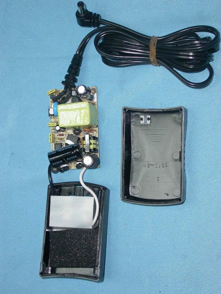
PKW-BEFW11S4V4
May 21, 2003Wireless Access Point Router
Equipment Class
DTS - Digital Transmission System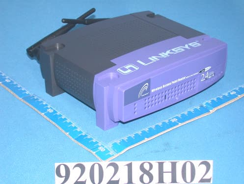
PKW-BEFW11S4V32
Apr 13, 2003Wireless Access Point Router with 4-Port Switch
Equipment Class
DTS - Digital Transmission System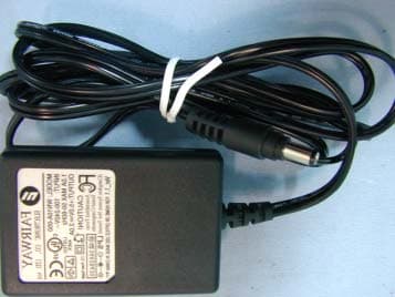
PKW-WSB24-2
Apr 03, 2003Wireless Signal Booster
Equipment Class
DTS - Digital Transmission System
PKW-BEFCMUH4
Apr 01, 2003Cable Gateway
Equipment Class
DTS - Digital Transmission System