PKW-WRT51ABDual Band Wireless A+B Broadband Router
Cisco-Linksys, LLC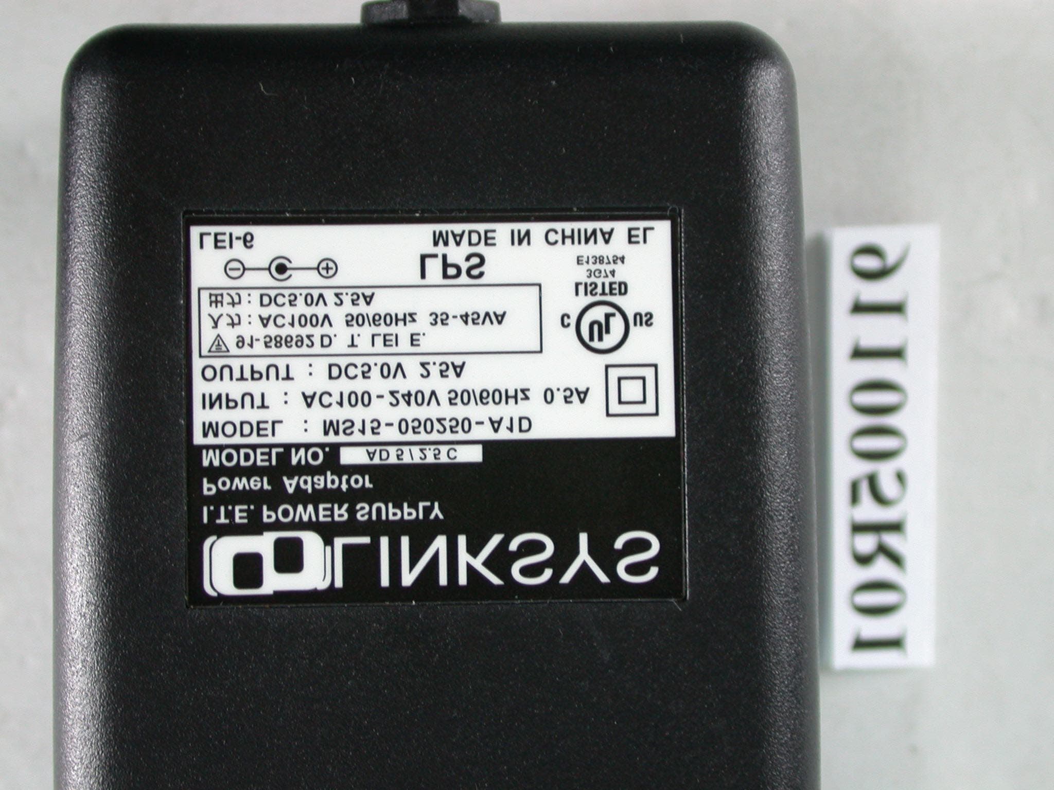
Click to zoom
Application Details
- Equipment Class
- DTS - Digital Transmission System
- Date of Grant
- Nov 07, 2002
- Application Purpose
- Original Equipment
- Date of Application
- Nov 07, 2002
- Equipment Note
- Dual Band Wireless A+B Broadband Router
- Frequency Range
- 2412.00000000 - 2462.00000000
- Company
- Cisco-Linksys, LLC
- Country
- United States
Documents & Files
Document Text
Text extracted from the exhibit documents filed with the FCC. Open a document above to read the original.
Users Manual
Instant Wireless ® Series Dual-Band Wireless A+BBroadband RouterUse this guide to install:WRT51AB User Guide FCC RF Radiation Exposure StatementTo comply with the FCC and ANSI C95.1 RF exposure limits, the antenna(s) for thisdevice must comply with the following: 1. Access points with 2.4 GHz or 5 GHz integrated antenna must operate with a sepa- ration distance of at least 20 cm from all persons using the cable provided and mustnot be co-located or operating in conjunction with any other antenna or transmitter. 2. The Access Point's co-located 2.4 GHz and 5 GHz integrated antennas support a minimum separation distance of 10 cm (3.9 in.) and are compliant with the applica-ble FCC RF exposure limit when transmitting simultaneously. End-users must be provided with specific operations for satisfying RF exposure compli-ance.Note: Dual antennas used for diversity operation are not considered co-located.Canadian Department of Communications Industry Canada (IC) NoticeThis Class B digital apparatus complies with Canadian ICES-003 and RSS-210.Cet appareil numérique de la classe B est conforme à la norme NMB-003 et CNR-210du Canada."To prevent radio interference to the licensed service, this device is intended to be oper-ated indoors and away from windows to provide maximum shielding. Equipment (or itstransmit antenna) that is installed outdoors is subject to licensing."" Pour empêcher que cet appareil cause du brouillage au service faisant l'objet d'unelicence, il doit être utilisé à l'intérieur et devrait être placé loin des fenêtres afin de fournirun écran de blindage maximal. Si le matériel (ou son antenne d'émission) est installé àl'extérieur, il doit faire l'objet d'une licence. "EC DECLARATION OF CONFORMITY (EUROPE)Linksys Group declares that the Instant Wireless ® Series products included in the Instant Wireless ® Series conform to the specifications listed below, following the provisions of the European R&TTE directive 1999/5/EC, EMC directive 89/336/EEC, and Low Voltagedirective 73/23/EEC: For 11Mpbs, 2.4 GHz access points with 100 mW radios, the following standards wereapplied: • ETS 300-826, 301 489-1 General EMC requirements for Radio equipment. • EN 609 50 Safety • ETS 300-328-2 Technical requirements for Radio equipment. For 54 Mpbs, 5 GHz access points with 40 mW radios, the following standards wereapplied: • ETS 301 489-1, 301 489-17 General EMC requirements for Radio equipment. • EN 609 50 Safety • ETS 301-893 Technical requirements for Radio equipment. Caution: The frequencies used by 802.11a wireless LAN devices are not yet harmonizedwithin the European community, 802.11a products are designed for use only in specificcountries, and are not allowed to be operated in countries other than those of designat-ed use. Contact local Authority for procedure to follow.Caution: This equipment is intended to be used in all EU and EFTA countries. Outdooruse may be restricted to certain frequencies and/or may require a license for operation.Contact local Authority for procedure to follow.Note: Combinations of power levels and antennas resulting in a radiated power level ofabove 100 mW equivalent isotropic radiated power (EIRP) are considered as not com-pliant with the above mentioned directive and are not allowed for use within the Europeancommunity and countries that have adopted the European R&TTE directive 1999/5/ECand/or the CEPT recommendation Rec 70.03. For more details on legal combinations of power levels and antennas, contact LinksysCorporate Compliance. COPYRIGHT & TRADEMARKS Copyright © 2002 Linksys, All Rights Reserved. Instant Wireless, Linksys, and theLinksys logo are registered trademarks of Linksys Group, Inc. Microsoft, Windows, andthe Windows logo are registered trademarks of Microsoft Corporation. All other trade-marks and brand names are the property of their respective proprietors. LIMITED WARRANTY Linksys guarantees that every Instant Wireless Dual-Band Wireless A+B BroadbandRouter will be free from physical defects in material and workmanship for one year fromthe date of purchase, when used within the limits set forth in the Specifications sectionof this User Guide. If the product proves defective during this warranty period, callLinksys Technical Support in order to obtain a Return Authorization number. BE SURE TOHAVE YOUR PROOF OF PURCHASE ON HAND WHEN CALLING. When returning aproduct, mark the Return Authorization number clearly on the outside of the package andinclude a copy of your original proof of purchase. RETURN REQUESTS CANNOT BEPROCESSED WITHOUT PROOF OF PURCHASE. All customers located outside of theUnited States of America and Canada shall be held responsible for shipping and han-dling charges.IN NO EVENT SHALL LINKSYS'S LIABILITY EXCEED THE PRICE PAID FOR THE PROD-UCT FROM DIRECT, INDIRECT, SPECIAL, INCIDENTAL, OR CONSEQUENTIAL DAM-AGES RESULTING FROM THE USE OF THE PRODUCT, ITS ACCOMPANYING SOFT-WARE, OR ITS DOCUMENTATION. LINKSYS OFFERS NO REFUNDS FOR ITS PROD-UCTS. Linksys makes no warranty or representation, expressed, implied, or statutory,with respect to its products or the contents or use of this documentation and all accom-panying software, and specifically disclaims its quality, performance, merchantability, orfitness for any particular purpose. Linksys reserves the right to revise or update its prod-ucts, software, or documentation without obligation to notify any individual or entity.Please direct all inquiries to:Linksys P.O. Box 18558, Irvine, CA 92623. SAFETY AND REGULATORY NOTICESFCC STATEMENTThe Instant Wireless Dual-Band Wireless A+B Broadband Router has been tested andfound to comply with the specifications for a Class B digital device, pursuant to Part 15of the FCC Rules. Operation is subject to the following two conditions: (1) This device may not cause harmful interference, and (2) This device must accept any interference received, including interference that may cause undesired operation. These limits are designed to provide reasonabl…
Text truncated - open the document above for the full version.
Users Manual
Dual-Band Wireless A+B Broadband Router DTIM Interval This value, between 1 and 16384, indicates the interval of the Delivery Traffic Indication Message (DTIM). A DTIM field is a countdownfield informing clients of the next window for listening to broadcast and mul-ticast messages. When the Router has buffered broadcast or multicast messagesfor associated clients, it sends the next DTIM with a DTIM Interval value. Itsclients hear the beacons and awaken to receive the broadcast and multicast mes-sages. The default value is 1 . RTS Threshold Should you encounter inconsistent data flow, only minor reduction of the default value, 2346, is recommended. If a network packet issmaller than the preset RTS threshold size, the RTS/CTS mechanism will notbe enabled. The Router sends Request to Send (RTS) frames to a particularreceiving station and negotiates the sending of a data frame. After receiving anRTS, the wireless station responds with a Clear to Send (CTS) frame toacknowledge the right to begin transmission. The RTS Threshold value shouldremain at its default value of 2346 . Fragmentation Threshold This value specifies the maximum size for a pack- et before data is fragmented into multiple packets. If you experience a highpacket error rate, you may slightly increase the Fragmentation Threshold.Setting the Fragmentation Threshold too low may result in poor network per-formance. Only minor reduction of the default value is recommended. In mostcases, it should remain at its default value of 2346 . Transmission Rate The rate of data transmission should be set depending on the speed of your wireless network. You can select from a range of transmissionspeeds ( 6 , 9 , 12 , 18 , 24 , 36 , 48 , or 54 Mbps), or you can select Best to have the Router automatically use the fastest possible data rate and enable the Auto-Fallback feature. Auto-Fallback will negotiate the best possible connectionspeed between the Router and a wireless client. The default value is Best . Transmit Power The greater the transmit power used, the larger the area a wireless network covers. To minimize the likelihood of eavesdropping by unau-thorized wireless users, do not use more transmit power than necessary to coverthe range needed for your wireless network. Try using the Router at differentlevels of transmit power, and determine how much transmit power is needed toreach the wireless client, such as a PC, or access point that is farthest from theRouter. Then select the appropriate level of transmit power ( Full , Half , Quarter , Eighth , or Min ) from the drop-down menu. The default value is Full . 49 Instant Wireless ® Series The Advanced Wireless screen allows you to customize data transmission set- tings and access the 802.1x Configuration screen. In most cases, the advanced wireless settings on this screen should remain at their default values. 5GHz, 802.11aBeacon Interval The Beacon Interval value indicates the frequency interval of the beacon. Enter a value between 20 and 1000. A beacon is a packet broadcastby the Router to synchronize the wireless network. The default value is 100 . 48 Advanced Wireless Figure 6-19 Dual-Band Wireless A+B Broadband Router 802.1x ConfigurationThe 802.1x Configuration screen allows you to alter the 802.1x settings for your wireless network(s). Based on the Extensible Authentication Protocol(EAP), the 802.1x standard specifies an authentication framework for awireless client to access a network, so network security is enhanced.To access a network with 802.1x enabled, wireless clients, such as PCs,must use 802.1x client software or Windows XP, which supports 802.1x. 51 Instant Wireless ® Series 2.4GHz, 802.11bBeacon Interval The Beacon Interval value indicates the frequency interval of the beacon. Enter a value between 20 and 1000. A beacon is a packet broadcastby the Router to synchronize the wireless network. The default value is 100 . RTS Threshold Should you encounter inconsistent data flow, only minor reduction of the default value, 2346, is recommended. If a network packet issmaller than the preset RTS threshold size, the RTS/CTS mechanism will notbe enabled. The Router sends Request to Send (RTS) frames to a particularreceiving station and negotiates the sending of a data frame. After receiving anRTS, the wireless station responds with a Clear to Send (CTS) frame toacknowledge the right to begin transmission. The RTS Threshold value shouldremain at its default value of 2346 . Fragmentation Threshold This value specifies the maximum size for a pack- et before data is fragmented into multiple packets. If you experience a highpacket error rate, you may slightly increase the Fragmentation Threshold.Setting the Fragmentation Threshold too low may result in poor network per-formance. Only minor reduction of this value is recommended. In most cases,it should remain at its default value of 2346 . Preamble Type The preamble defines the length of the CRC block for com- munication between the Router and a roaming wireless network adapter. Selectthe appropriate preamble type for your wireless network. (High network trafficareas should use the shorter preamble type.) The default is Long Preamble . Transmission Rate The rate of data transmission should be set depending on the speed of your wireless network. You can select from a range of transmissionspeeds ( 1 , 2 , 5.5 , or 11 Mbps), or you can select Best to have the Router auto- matically use the fastest possible data rate and enable the Auto-Fallback fea-ture. Auto-Fallback will negotiate the best possible connection speed betweenthe Router and a wireless client. The default setting is Best . To apply any of the settings you change on this page, click the Apply button. To cancel any changes you’ve entered on this page, click the Cancel button. To get more information about the features, click the Help button. 802.1x Configuration802.1x Configuration Click the 802.1x Configuration button to customize the Router’s 802.1x feature (see Figure 6-…
Text truncated - open the document above for the full version.
External Photos
Page 1 ANNEX PHOTOGRAPHS OF EUT Page 2 Page 3 Page 4 Page 5 Page 6 Page 7
Internal Photos
Page 8 Page 9 Page 10 Page 11 Page 12
Internal Photos
Page 13 Page 14 Page 15 Page 16
Operational Description
FCC ID: PKW-WRT51AB ADT No.911005R01 Technical Description The transmitter of the EUT is powered by power adapter and connected with PC through RJ45 port. The antenna is Dipole antenna. There is no antenna connector. Under normal use condition, the user has to keep at least 20cm separation distance between radiator and the body of the user. This device is a Dual-Band Wireless Access Point which can operate in both the 5GHz and 2.4GHz bands and can not transmitting simultaneously, the maximum data rate could be 72Mbps. For more detailed instruction, please take a look at the user’s manual. FCC 15.407(c) states : The device shall automatically discontinue transmission in case of either absence of information to transmit or operational failure. These provisions are not intended to preclude the transmission of control or signaling information or the use of repetitive codes used by certain digital technologies to complete frame or burst intervals. Applicants shall include in their application for equipment authorization a description of hoe this requirement is met” Data transmission is always initiated by software, which is then pass down through the MAC, through the digital and analog baseband, and finally to the RF chip. Several special packets (ACKs, CTS, PSPoll, etc...) are initiated by the MAC. There are the only ways the digital baseband portion will turn on the RF transmitter, which it then turns off at the end of the packet. Therefore, the transmitter will be on only while one of the aforementioned packets are being transmitted.
RF Exposure Info
ADT No: 911005R01 1 FCC TEST REPORT REPORT NO.: RF911005R01 MODEL NO.: WRT51AB ACCORDING: FCC Guidelines for Human Exposure IEEE C95.1 APPLICANT:The Linksys Group, Inc. ADDRESS:17401 Armstrong Ave., Irvine, CA 92614 ISSUED BY:Advance Data Technology Corporation LAB LOCATION:47 14th Lin, Chiapau Tsun, Linko, Taipei, Taiwan, R.O.C. 0528 ILAC MRA Lab Code: 200102-0 ADT No: 911005R01 2 RF Exposure Measurement 1. Introduction In this document, we try to prove the safety of radiation harmfulness to the human body for our product. The limit for Maximum Permissible Exposure (MPE) specified in FCC 1.1310 is followed. The Gain of the antenna used in this product is measured in a Fully Anechoic Chamber (FAC) calibrated for antenna measurement in ADT, and also the maximum total power input to the antenna is measured. Through the Friis transmission formula and the maximum gain of the antenna, we can calculate the distance, away from the product, where the limit of MPE is reached. Although the Friis transmission formula is a far field assumption, the calculated result of that is an over-prediction for near field power density. We will take that as the worst case to specify the safety range. 2. RF Exposure Limit According to FCC 1.1310: The criteria listed in the following table shall be used to evaluate the environmental impact of human exposure to radio-frequency (RF) radiation as specified in 1.1307(b) LIMITS FOR MAXIMUM PERMISSIBLE EXPOSURE (MPE) Frequency Range (MHz) Electric Field Strength (V/m) Magnetic Field Strength (A/m) Power Density (mW/cm 2 ) Average Time (minutes) (A)Limits For Occupational / Control Exposures 300-1500......F/3006 1500-100,000......56 (B)Limits For General Population / Uncontrolled Exposure 300-1500......F/15006 1500-100,000......1.030 F = Frequency in MHz ADT No: 911005R01 3 3. Friis Formula Friis transmission formula : Pd = (Pout*G) / (4*pi*r 2 ) where Pd = power density in mW/cm 2 Pout = output power to antenna in mW G = gain of antenna in linear scale Pi = 3.1416 R = distance between observation point and center of the radiator in cm Pd is the limit of MPE, 1 mW/cm 2 . If we know the maximum Gain of the antenna and the total power input to the antenna, through the calculation, we will know the distance r where the MPE limit is reached. Ref. : David K. Cheng, Field and Wave Electromagnetics, Second Edition, Page 640, Eq. (11-133). 4 EUT Operating condition The software provided by Manufacturer enabled the EUT to transmit and receive data at lowest, middle and highest channel individually. 5 Climate Condition The temperature and related humidity: 20 deg. C and 63 % RH 6. Classification This device is not fixed inside the host equipment, it is connected with host through wire. So it is easy to be re-located in the place where at least 20cm far away from the body of the user. Warning statement to the user for keeping at least 20cm or more separation distance with the antenna should be included in users manual. So, this device is classified as Mobile Device. ADT No: 911005R01 4 7 Test Results 7.1 Antenna Gain The maximum Gain measured in Fully Anechoic Chamber are 1dBi or 1.26 (numeric) for 5GHz and 2.4GHz. 7.2 Output Power Into Antenna & RF Exposure Distance : For Part 802.11b: CHANNEL CHANNEL FREQUENCY (MHz) OUTPUT POWER TO ANTENNA (mW) MINIMUM ALLOWABLE DISTANCE ( r ) FROM SKIN (Centi-Meter) 1241217.781.33 6243716.601.29 11246214.451.20 For Part 802.11a: Normal Mode: CHANNEL CHANNEL FREQUENCY (MHz) OUTPUT POWER TO ANTENNA (mW) MINIMUM ALLOWABLE DISTANCE ( r ) FROM SKIN (Centi-Meter) 1518025.001.58 4524020.091.42 5526033.271.83 8532021.131.46 Turbo Mode: CHANNEL CHANNEL FREQUENCY (MHz) OUTPUT POWER TO ANTENNA (mW) MINIMUM ALLOWABLE DISTANCE ( r ) FROM SKIN (Centi-Meter) 1521017.861.34 2525015.141.23 3529012.471.77 The minimum allowable distance is very close to the enclosure of the antenna. So, the user has no need to worry about the harmfulness of radiation. But it is recommended to always keep, at least, 20cm separation distance with the antenna.
Test Report
FCC ID: PKW-WRT51AB Report No.: RF911005R01 1 Issued: Nov. 5, 2002 FCC TEST REPORT REPORT NO.: RF911005R01 MODEL NO.: WRT51AB RECEIVED: Sept. 4, 2002 TESTED: Sept. 4 ~ Nov. 4, 2002 APPLICANT:The Linksys Group, Inc. ADDRESS:17401 Armstrong Ave., Irvine, CA 92614 ISSUED BY:Advance Data Technology Corporation LAB LOCATION:47 14 th Lin, Chiapau Tsun, Linko, Taipei, Taiwan, R.O.C. This test report consists of 133 pages in total. It may be duplicated completely for legal use with the approval of the applicant. It should not be reproduced except in full, without the written approval of our laboratory. The client should not use it to claim product endorsement by CNLA, NVLAP or any government agencies. The test results in the report only apply to the tested sample. 0528 ILAC MRA Lab Code: 200102-0 FCC ID: PKW-WRT51AB Report No.: RF911005R01 2 Issued: Nov. 5, 2002 Table of Contents 1CERTIFICATION........................................................................................... 5 2SUMMARY OF TEST RESULTS .................................................................. 6 3GENERAL INFORMATION ........................................................................... 8 3.1GENERAL DESCRIPTION OF EUT ...................................................................................... 8 3.2DESCRIPTION OF TEST MODES ........................................................................................ 9 3.3GENERAL DESCRIPTION OF APPLIED STANDARDS ..................................................... 10 3.4DESCRIPTION OF SUPPORT UNITS................................................................................. 11 4TEST TYPES AND RESULTS (FOR PART 802.11b) ................................. 12 4.1CONDUCTED EMISSION MEASUREMENT....................................................................... 12 4.1.1LIMITS OF CONDUCTED EMISSION MEASUREMENT .................................................... 12 4.1.2TEST INSTRUMENTS ......................................................................................................... 12 4.1.3TEST PROCEDURES .......................................................................................................... 13 4.1.4DEVIATION FROM TEST STANDARD ................................................................................ 13 4.1.5TEST SETUP ....................................................................................................................... 14 4.1.6EUT OPERATING CONDITIONS......................................................................................... 14 4.1.7TEST RESULTS ................................................................................................................... 15 4.2RADIATED EMISSION MEASUREMENT ............................................................................ 21 4.2.1LIMITS OF RADIATED EMISSION MEASUREMENT ......................................................... 21 4.2.2TEST INSTRUMENTS ......................................................................................................... 22 4.2.3TEST PROCEDURES .......................................................................................................... 23 4.2.4DEVIATION FROM TEST STANDARD ................................................................................ 23 4.2.5TEST SETUP ....................................................................................................................... 24 4.2.6EUT OPERATING CONDITIONS......................................................................................... 24 4.2.7TEST RESULTS................................................................................................................... 25 4.36dB BANDWIDTH MEASUREMENT ................................................................................... 30 4.3.1LIMITS OF 6dB BANDWIDTH MEASUREMENT ................................................................ 30 4.3.2TEST INSTRUMENTS ......................................................................................................... 30 4.3.3TEST PROCEDURE ............................................................................................................31 4.3.4DEVIATION FROM TEST STANDARD ................................................................................ 31 4.3.5TEST SETUP ....................................................................................................................... 31 4.3.6EUT OPERATING CONDITIONS......................................................................................... 31 4.3.7TEST RESULTS ................................................................................................................... 32 4.4MAXIMUM PEAK OUTPUT POWER ................................................................................... 36 4.4.1LIMITS OF MAXIMUM PEAK OUTPUT POWER MEASUREMENT ................................... 36 4.4.2INSTRUMENTS.................................................................................................................... 36 4.4.3TEST PROCEDURES .......................................................................................................... 37 4.4.4DEVIATION FROM TEST STANDARD ................................................................................ 37 4.4.5TEST SETUP ....................................................................................................................... 37 4.4.6EUT OPERATING CONDITIONS......................................................................................... 37 FCC ID: PKW-WRT51AB Report No.: RF911005R01 3 Issued: Nov. 5, 2002 4.4.7TEST RESULTS ................................................................................................................... 38 4.5POWER SPECTRAL DENSITY MEASUREMENT .............................................................. 39 4.5.1LIMITS OF POWER SPECTRAL DENSITY MEASUREMENT ........................................... 39 4.5.2TEST INSTRUMENTS ..........…
Text truncated - open the document above for the full version.
Test Report
FCC ID: PKW-WRT51AB Report No.: RF911005R01 101 Issued: Nov. 5, 2002 CHANNEL 5 FCC ID: PKW-WRT51AB Report No.: RF911005R01 102 Issued: Nov. 5, 2002 CHANNEL 8 FCC ID: PKW-WRT51AB Report No.: RF911005R01 103 Issued: Nov. 5, 2002 EUT Dual-Band Wireless A+B Broadband Router MODEL WRT51AB MODE Turbo INPUT POWER (SYSTEM) 120Vac, 60 Hz ENVIRONMENTAL CONDITIONS 23deg. C, 64%RH, 1005 hPa TESTED BY Steven Lu CHANNEL CHANNEL FREQUENCY (MHz) PEAK POWER EXCURSION (dB) PEAK to AV E R AG E EXCURSION LIMIT (dB) PASS/FAIL 1521010.0413PASS 2525010.9013PASS 3529010.9613PASS FCC ID: PKW-WRT51AB Report No.: RF911005R01 104 Issued: Nov. 5, 2002 CHANNEL 1 FCC ID: PKW-WRT51AB Report No.: RF911005R01 105 Issued: Nov. 5, 2002 CHANNEL 2 FCC ID: PKW-WRT51AB Report No.: RF911005R01 106 Issued: Nov. 5, 2002 CHANNEL 3 FCC ID: PKW-WRT51AB Report No.: RF911005R01 107 Issued: Nov. 5, 2002 5.5 PEAK POWER SPECTRAL DENSITY MEASUREMENT 5.5.1 LIMITS OF PEAK POWER SPECTRAL DENSITY MEASUREMENT Frequency BandLimit 5.15 – 5.25 GHz4dBm 5.25 – 5.35 GHz11dBm 5.725 – 5.825 GHz17dBm 5.5.2 TEST INSTRUMENTS Description & ManufacturerModel No.Serial No.Calibrated Until ROHDE&SCHWARZ SPECTRUM ANALYZER FSEK30100049July 24, 2003 NOTE: 1. The measurement uncertainty is less than +/- 2.6dB, which is calculated as per the NAMAS document NIS81. 2. The calibration interval of the above test instruments is 12 months and the calibrations are traceable to NML/ROC and NIST/USA. FCC ID: PKW-WRT51AB Report No.: RF911005R01 108 Issued: Nov. 5, 2002 5.5.3 TEST PROCEDURES 1. The transmitter output was connected to the spectrum analyzer. 2. Set RBW=1MHz, VBW=3MHz. The PPSD is the highest level found across the emission in any 1MHz band. 5.5.4 DEVIATION FROM TEST STANDARD No deviation 5.5.5 TEST SETUP 5.5.6 EUT OPERATING CONDITIONS Same as 5.3.6 EUT SPECTRUM ANALYZER FCC ID: PKW-WRT51AB Report No.: RF911005R01 109 Issued: Nov. 5, 2002 5.5.7 TEST RESULTS EUT Dual-Band Wireless A+B Broadband Router MODEL WRT51AB MODE Normal INPUT POWER (SYSTEM) 120Vac, 60 Hz ENVIRONMENTAL CONDITIONS 23deg. C, 64%RH, 1005 hPa TESTED BY Steven Lu CHANNEL NUMBER CHANNEL FREQUENCY (MHz ) RF POWER LEVEL IN 1 MHz BW (dBm) MAXIMUM LIMIT (dBm) PASS/FAIL 15180-3.724PASS 45240-2.964PASS 55260-0.1811PASS 85320-2.5811PASS FCC ID: PKW-WRT51AB Report No.: RF911005R01 110 Issued: Nov. 5, 2002 CHANNEL 1 FCC ID: PKW-WRT51AB Report No.: RF911005R01 111 Issued: Nov. 5, 2002 CHANNEL 4 FCC ID: PKW-WRT51AB Report No.: RF911005R01 112 Issued: Nov. 5, 2002 CHANNEL 5 FCC ID: PKW-WRT51AB Report No.: RF911005R01 113 Issued: Nov. 5, 2002 CHANNEL 8 FCC ID: PKW-WRT51AB Report No.: RF911005R01 114 Issued: Nov. 5, 2002 EUT Dual-Band Wireless A+B Broadband Router MODEL WRT51AB MODE Turbo INPUT POWER (SYSTEM) 120Vac, 60 Hz ENVIRONMENTAL CONDITIONS 23deg. C, 64%RH, 1005 hPa TESTED BY Steven Lu CHANNEL NUMBER CHANNEL FREQUENCY (MHz ) RF POWER LEVEL IN 1 MHz BW (dBm) MAXIMUM LIMIT (dBm) PASS/FAIL 15210-4.144PASS 25250-5.014PASS 35290-6.2311PASS FCC ID: PKW-WRT51AB Report No.: RF911005R01 115 Issued: Nov. 5, 2002 CHANNEL 1 FCC ID: PKW-WRT51AB Report No.: RF911005R01 116 Issued: Nov. 5, 2002 CHANNEL 2 FCC ID: PKW-WRT51AB Report No.: RF911005R01 117 Issued: Nov. 5, 2002 CHANNEL 3 FCC ID: PKW-WRT51AB Report No.: RF911005R01 118 Issued: Nov. 5, 2002 5.6 FREQUENCY STABILITY 5.6.1 LIMITS OF FREQUENCY STABILITY MEASUREMENT The frequency tolerance of the carrier signal shall be maintained within +/- 0.02% of the operating frequency over a temperature variation of –30 degrees to 50 degrees C at normal supply voltage, and for a variation in the primary supply voltage from 85% to 115% of the rated supply voltage at a temperature of 20 degrees C. 5.6.2 TEST INSTRUMENTS Description & ManufacturerModel No.Serial No.Calibrated Until ANRITSU SPECTRUM ANALYZERMS2667CM10281Mar. 15, 2003 WIT STANDARD TEMPERATURE AND HUMIDITY CHAMBER TH-4S-CW901030Jun. 24, 2003 NOTE: The measurement uncertainty is less than +/- 2.6dB, which is calculated as per the NAMAS document NIS81. The calibration interval of the above test instruments is 12 months and the calibrations are traceable to NML/ROC and NIST/USA. 5.6.3 TEST PROCEDURE 1. The EUT was placed inside the environmental test chamber and powered by nominal DC voltage. 2. Turn the EUT on and couple its output to a spectrum analyzer. 3. Turn the EUT off and set the chamber to the highest temperature specified. 4. Allow sufficient time (approximately 30 min) for the temperature of the chamber to stabilize, turn the EUT on and measure the operating frequency after 2, 5, and 10 minutes. 5. Repeat step 2 and 3 with the temperature chamber set to the lowest temperature. 6. The test chamber was allowed to stabilize at +20 degree C for a minimum of 30 minutes. The supply voltage was then adjusted on the EUT from 85% to 115% and the frequency record. FCC ID: PKW-WRT51AB Report No.: RF911005R01 119 Issued: Nov. 5, 2002 5.6.4 DEVIATION FROM TEST STANDARD No deviation 5.6.5 TEST SETUP 5.6.6 EUT OPERATING CONDITION Same as Item 4.1.6 Spectrum Analyzer DC Power Supply Temperature Chamber FCC ID: PKW-WRT51AB Report No.: RF911005R01 120 Issued: Nov. 5, 2002 5.6.7 TEST RESULTS Operating frequency: 5180MHz Limit : ± 0.02% 2 minute5 minute10 minute Temp. (°C °C°C °C) Power supply (VDC) (MHz)(%)(MHz)(%)(MHz)(%) 126.5 5179.9914-0.00016605179.9920-0.00015445179.9918-0.0001583 110.0 5179.9912-0.00016995179.9914-0.00016605179.9916-0.0001622 50 93.5 5179.9912-0.00016995179.9916-0.00016225179.9918-0.0001583 126.5 5179.9780-0.00042475179.9778-0.00042865179.9778-0.0004286 110.0 5179.9780-0.00042475179.9780-0.00042475179.9778-0.0004286 40 93.5 5179.9778-0.00042865179.9778-0.00042865179.9780-0.0004247 126.5 5179.9702-0.00057535179.9706-0.00056765179.9706-0.0005676 110.0 5179.9704-0.00057145179.9706-0.00056765179.9706-0.0005676 30 93.5 5179.9702-0.00057535179.9706-0.00056765179.9706-0.0005676 126.5 5179.9724-0.00053285179.9724-0.00053285179.9726-0.0005290 110.0 5179.9724-0.00053285179.9724-0.00053285179.9726-0.0005290 20 …
Text truncated - open the document above for the full version.
Test Setup Photos
FCC ID: PKW-WRT51AB Report No.: RF911005R01 131 Issued: Nov. 5, 2002 6 PHOTOGRAPHS OF THE TEST CONFIGURATION CONDUCTED EMISSION TEST FCC ID: PKW-WRT51AB Report No.: RF911005R01 132 Issued: Nov. 5, 2002 RADIATED EMISSION TEST
Contact Information
Applicant
Ms Jennifer Yu(Associate Engineer)
Technical Contact
Advance Data Technology CorporationVivi Wang
[email protected]+886 3 327 0910
13-1, Lane 19, WenShan 3rd St · Taoyuan · Taiwan
Test Firm
Bureau Veritas CPS (H.K.) Ltd. Taoyuan BranchRichard Chen
Technical Specifications
| # | Rule Parts | Frequency Range | Power Output |
|---|---|---|---|
| 1 | 15C | 2.41 GHz - 2.46 GHz | 18.00 mW |
Other Applications from Cisco-Linksys, LLC

PKW-WMP54GV2
May 29, 2003Wireless-G PCI Adapter
Equipment Class
DTS - Digital Transmission System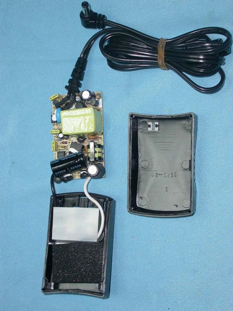
PKW-BEFW11S4V4
May 21, 2003Wireless Access Point Router
Equipment Class
DTS - Digital Transmission System
PKW-BEFW11S4V32
Apr 13, 2003Wireless Access Point Router with 4-Port Switch
Equipment Class
DTS - Digital Transmission System
PKW-WSB24-2
Apr 03, 2003Wireless Signal Booster
Equipment Class
DTS - Digital Transmission System
PKW-BEFCMUH4
Apr 01, 2003Cable Gateway
Equipment Class
DTS - Digital Transmission System