PKW-WSB24-1Wireless Router with Booster
Cisco-Linksys, LLC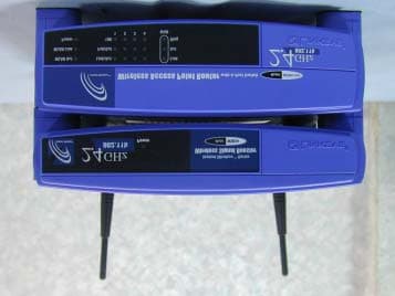
Click to zoom
Application Details
- Equipment Class
- DTS - Digital Transmission System
- Date of Grant
- Dec 23, 2002
- Application Purpose
- Original Equipment
- Date of Application
- Dec 23, 2002
- Equipment Note
- Wireless Router with Booster
- Frequency Range
- 2412.00000000 - 2462.00000000
- Company
- Cisco-Linksys, LLC
- Country
- United States
Documents & Files
Document Text
Text extracted from the exhibit documents filed with the FCC. Open a document above to read the original.
Users Manual
WWW. LINKS YS . C O M A. With your Access Point/Router powered off, place the Wireless Signal Booster on top of the Access Point/Router. B. Disconnect the Access Point’s/Router’s a ntennas. C. Connect the Signal Booster Cables from the Access Point’s/Router’s a nten- na ports to the Wireless Si gnal Booster’s cable ports. D. Connect the antennas to the Wireless Signal Booster’s a ntenna ports. E. Connect the appropriate power adapters to both the Access Point/Router and Wireless Signal Booster. F. Now you are ready to use the Wireless Signal Booster in your wireless network. Connecting the Wireless Signal Booster toYour Linksys Access Point/Router QI-WSB24-10/25/02NC BW B Package Contents• One Linksys W ireless Signal Booster • Two Signal Booster Cables• Two Power Adapters• One Quick Installation and User Guide • One Wireless Router, BEFW11S4 Wireless Signal Booster Instant Wireless ® WSB24-1 The Wireless Signal Booster with Access Point C D E Note: The images in this document show the Wireless Signal Booster being con- nected to an Access Point; the same directions can be followed when connecting theWireless Signal Booster to a wireless Router. wsb24 quick install-2.qxd 2002/12/20 ¤U¤È 04:07 Page 1 COPYRIGHT & TRADEMARKSCopyright c 2002 Linksys, All Rights Reserved. All other trademarks and brandnames are the property of their respective proprietors.LIMITED WARRANTYLinksys guarantees that every Wireless Signal Booster WSB24-1 is free from physi-cal defects in material and workmanship under normal use for one years from thedate of purchase. If the product proves defective during this warranty period, callLinksys Customer Support in order to obtain a Return Authorization Number. BESURE TO HAVE YOUR PROOF OF PURCHASE ON HAND WHEN CALLING.RETURN REQUESTS CANNOT BE PROCESSED WITHOUT PROOF OF PUR-CHASE. When returning a product, mark the Return Authorization Number clearlyon the outside of the package and include a copy of your original proof of purchase.All customers outside of the United States of America and Canada shall be heldresponsible for shipping and handling charges.IN NO EVENT SHALL LIN KSYS’ LIABILITY EXCEED THE PRICE PAID FOR THE PRODUCT FROM DEFECT, INDIRECT, SPECIAL, INCIDENTAL, OR CONSE-QUENTIAL DAMAGES RESULTING FROM THE USE OF THE PRODUCT, ITSACCOMPANYING SOFTWARE, OR ITS DOCUMENTATION. LINKSYS DOES NOTISSUE REFUNDS. WARRANTY DOES NOT COVER NATURAL DISASTERS ORACTS OF NATURE.Linksys makes no warranty or representation, expressed, implied, or statutory, withrespect to its products or the contents use of this documentation and all accompany-ing software, and specially disclaims its quality, performance, merchantability, or fit-ness for any particular purpose. Linksys reserves the right to revise or update itsproducts, software, or documentation without obligation to notify any individual orentity. Please direct all inquiries to :Linksys P.O.Box 18558, Irvine, CA 92623CAUTION : ANY CHANGES OR MODIFICATIONS NOT EXPRESSLY APPROVED IN THIS MANUAL COULD VOID YOUR AUTHORIZATION TO USETHIS DEVICE. This device should be operated at least 2.0m away from any person FCC STATEMENTThe Wireless Signal Booster WSB24-1 has been tested and found to comply withthe limits for a class B digital device, pursuant to part 15 of the FCC Rules. Theselimits are designed to provide reasonable protection against harmful interference in aresidential installation.This equipment generates, uses and can radiate radio frequency energy and, if notinstalled and used in accordance with the instructions, may cause harmful interfer-ence to radio communications. However, there is no guarantee that interference willnot occur in a particular installation. If this equipment does cause harmful interfer-ence to radio or television reception, which can be determined by turning the equip-ment off and on, the user is encouraged to try to correct the interference by one ormore of the following measures:—-Reorient or relocate the rece iving antenna. —-Increas e the separation between the equipment and receiver. —-Connect the equipment into an outlet on a circuit different from that to which the receiver is connected. —-Con sult the dealer or an experienced radio/TV technician for help. Regulatory information / DisclaimersInstallation and use of this Wireless LAN device must be in strict accordance withthe instructions included in the user documentation provided with the product. Anychanges or modifications (including the antennas) made to this device that are notexpressly approved by the manufa cturer may void the user’s authority to operate the equipment. The manufacturer is not responsible for any radio or television inter-ference caused by unauthorized modification of this device, or the substitution of theconnecting cables and equipment other than manufacturer specified. It is the respon-sibility of the user to correct any interference caused by such unauthorized modifica-tion, substitution or attachment. Manufacturer and its authorized resellers or distribu-tors will assume no liability for any damage or violation of government regulationsarising from failing to comply with these guidelines.CAUTION: To maintain compli ance with FCC’sRF exposure guidelines, this equipment should be installed and operated with minimum distance20cm between the radiator and your body. Use on the suppliedantenna. Unauthorized antenna, modification, or attachments coulddamage the transmitter and may violate FCC regulations. MPE Statement (Safety Information)Your device contains a low power transmitter. When device is transmitted it sendsout Radio Frequency (RF) signal.Safety InformationIn order to maintain compliance with the FCC RF exposure guidelines, this equip-ment should be installed and operated with minimum distance 20cm between theradiator and your body.Use only with supplied antenna. Unauthorized antenna, modification, or attachmentscould damage the transmitter and may violate FCC regulations.Caution Statement of the FCC Radio Freque…
Text truncated - open the document above for the full version.
Users Manual
Instant Wir eless™ Series Wireless Access Point Router with 4-Port Switch Use this Guide to install:BEFW11S4 Fast Start Guide EC DECLARATION OF CONFORMITY (EUROPE)Linksys Group declares that the Instant Wir eless™ Series pr oducts included in the Instant Wireless™ Series conform to the specifications listed below, following the provisions of the EMC Directive 89/336/EEC and Low Voltage Directive 73/23/EEC:• ETS 300-826, 301 489-1 General EMC requirements for Radio equipment. • EN 609 50 Safety • ETS 300-328-2 Technical requirements for Radio equipment. Note: This equipment is intended to be used in all EU and EFTA countries. Outdoor usemay be restricted to certain frequencies and/or may require a license for operation. Formore details, contact Linksys Corporate Compliance.Note: Combinations of power levels and antennas resulting in a radiated power level ofabove 100 mW are considered as not compliant with the above mentioned directive andare not allowed for use within the European community and countries that have adoptedthe European R&TTE directive 1999/5/EC and/or the CEPT recommendation Rec 70.03.For more details on legal combinations of power levels and antennas, contact LinksysCorporate Compliance.• Linksys Gr oup™ vakuuttaa täten että Instant Wir eless IEEE 802.11 PC Card tyyppinen laite on direktiivin 1999/5/EY, direktiivin 89/336/EEC ja direktiivin 73/23/EEC oleellis-ten vaatimusten ja sitä koskevien näiden direktiivien muiden ehtojen mukainen. • Linksys Gr oup™ déclare que la carte PC Instant Wireless IEEE 802.11 est conforme aux conditions essentielles et aux dispositions relatives à la directive 1999/5/EC, ladirective 89/336/EEC, et à la directive 73/23/EEC. • Belgique B L’utilisation en extérieur est autorisé sur le canal 11 (2462 MHz), 12 (2467MHz), et 13 (2472 MHz).Dans le cas d’une utilisation privée, à l’extérieur d’un bâtiment, au-dessus d’unespace public, aucun enregistrement n’est nécessaire pour une distance de moinsde 300m. Pour une distance supérieure à 300m un enregistrement auprès de l’IBPTest requise. Pour une utilisation publique à l’extérieur de bâtiments, une licence del’IBPT est requise. Pour les enregistrements et licences, veuillez contacter l’IBPT. • France F: Bande de fréquence restreinte: seuls les canaux 10, 11, 12, 13 (2457,2462, 2467, et 2472 MHz respectivement) doivent être utilisés en France. Toute util-isation, qu'elle soit intérieure ou extérieure, est soumise à autorisation. Vous pouvezcontacter l'Autorité de Régulation des Télécommuniations (http://www.art-telecom.fr)pour la procédure à suivre. • France F: Restricted frequency band: only channels 10, 11, 12, 13 (2457, 2462,2467, and 2472 MHz respectively) may be used in France. License required forevery indoor and outdoor installations. Please contact ART for procedure to follow. • Deutschland D: Anmeldung im Outdoor-Bereich notwending, aber nicht genehmi-gungspflichtig. Bitte mit Händler die Vorgehensweise abstimmen. • Germany D: License required for outdoor installations. Check with reseller for proce-dure to follow. • Italia I: E' necessaria la concessione ministeriale anche per l'uso interno. Verificarecon i rivenditori la procedura da seguire. L'uso per installazione in esterni non e' per-messa. • Italy I: License required for indoor use. Use with outdoor installations not allowed. • the Netherlands NL License required for outdoor installations. Check with reseller forprocedure to follow. • Nederlands NL Licentie verplicht voor gebruik met buitenantennes. Neem contact opmet verkoper voor juiste procedure. 1 Table of ContentsEnglish 2 Français 30 Deutsch 58 Italiano 86 Portuguese 114 Español 142 COPYRIGHT & TRADEMARKS Copyright © 2002 Linksys, All Rights Reserved. Instant Wireless is a trademark ofLinksys. Microsoft, Windows, and the Windows logo are registered trademarks ofMicrosoft Corporation. All other trademarks and brand names are the property of theirrespective proprietors. FCC STATEMENTThe Instant Wir eless™ Wir eless Access Point Router with 4-Port Switch has been tested and complies with the specifications for a Class B digital device, pursuant to Part 15 ofthe FCC Rules. These rules are designed to provide reasonable protection againstharmful interference in a residential installation. This equipment generates, uses, andcan radiate radio frequency energy and, if not installed and used according to theinstructions, may cause harmful interference to radio communications. However, there isno guarantee that interference will not occur in a particular installation. If this equipmentdoes cause harmful interference to radio or television reception, which is found by turn-ing the equipment off and on, the user is encouraged to try to correct the interference byone or more of the following measures:• Reorient or relocate the receiving antenna• Increase the separation between the equipment or devices• Connect the equipment to an outlet other than the receiver’s• Consult a dealer or an experienced radio/TV technician for assistance Table of ContentsIntroduction 4 Step 1: Connect the Router 6 Step 2: Configure the PCs 8 Step 3: Configure the Router 12 Help 16 Configuring Wireless Security 21 Configuring WirelessSecurity in Windows XP 24 FSG-BEFW11S4 ver. 3-21008 TE 3 2 For product support and product registration, contact us at the addresses below:E-mail [email protected]@linksys.com We b http://www.linksys.com/international Use the instructions in this Fast Start to help you connect the Router, configure yourPCs, and configure the Router in your network. These instructions should be all youneed to get you up and running with a basic network, sharing your Internet access.The Router also comes equipped with more advanced functions, but these functionsshould not be utilized without a further understanding of routers and networks.These and other issues are explained in the User Guide on the Setup Wizard CD-ROM.The Router’s setup is similar to that shown in the figure above …
Text truncated - open the document above for the full version.
External Photos
Spectrum Research & Testing Lab., Inc. No. 101-10, Ling 8, Shan-Tong Li, Chung-Li City, Taoyuan, Taiwan Tel: 886-3-4987684 Fax:: 886-3-4986528 PHOTOS OF EUT (Router with Booster) Spectrum Research & Testing Lab., Inc. No. 101-10, Ling 8, Shan-Tong Li, Chung-Li City, Taoyuan, Taiwan Tel: 886-3-4987684 Fax:: 886-3-4986528 PHOTOS OF EUT (Router) Spectrum Research & Testing Lab., Inc. No. 101-10, Ling 8, Shan-Tong Li, Chung-Li City, Taoyuan, Taiwan Tel: 886-3-4987684 Fax:: 886-3-4986528 PHOTOS OF EUT (Booster)
ID Label/Location Info
RD / IE NOTE: 1. 2. : 55.5x12.7mm 3. +- 1 mm WB1000#LK LBWB1000-RCC-LK100 V1.0 10/31/2002 CorelDRAW 9.0 Erica ext. 6104 = 12.7 mm 55.5mm FCC ID:PKW-WSB24-1 FCC ID:PKW-WSB24-1 1:1NON
ID Label/Location Info
Spectrum Research & Testing Lab., Inc. No. 101-10, Ling 8, Shan-Tong Li, Chung-Li City, Taoyuan, Taiwan Tel: 886-3-4987684 Fax:: 886-3-4986528 ID LABEL FCC Location
Operational Description
Operational Description The WSB24 consists of a RF power amplifier and a wireless access point router, BEFW11S4. ÿ The operational Frequency Band: 2400~2483.5MHz ÿ Number of channel: 11 ÿ Channel spacing: 5 MHz ÿ Rated RF output power: 120.2mW ÿ Modulation type: QPSK/BPSK/CCK ÿ Bit rate of transmission: 11Mbps ÿ Antenna type: Sleeve dipole To Access Point / Router Other description for the Signal Booster:
Test Report
Spectrum Research & Testing Lab., Inc. No. 101-10, Ling 8, Shan-Tong Li, Chung-Li City, Taoyuan, Taiwan TEST REPORT Reference No.:A02121801 Report No.:FCCA02121801 FCC ID:PKW-WSB24-1 Page:1 of 1 Date: Dec. 18, 2002 Lab Code: 200099-0 Product Name: Wireless Router with Signal Booster (SB) Model Number: WSB24-1 Applicant: THE LINKSYS GROUP, INC. 17401 ARMSTRONG AVE., IRVINE, CA 92614, U.S.A. Date of Receipt: Dec. 1, 2002 Finished date of Test: Dec. 4, 2002 Applicable Standards: 47 CFR Part 15, Subpart C ANSI C63.4:1992 We, Spectrum Research & Testing Laboratory Inc., hereby certify that one sample of the above was tested in our laboratory with positive results according to the above- mentioned standards. The records in the report are an accurate account of the results. Details of the results are given in the subsequent pages of this report. Tested By : , Date: Checked By : ( James Lee ) , Date: Approved By : (Spring Wang) , Date: ( Harris W. Lai, Director ) Spectrum Research & Testing Lab., Inc. No. 101-10, Ling 8, Shan-Tong Li, Chung-Li City, Taoyuan, Taiwan TEST REPORT Reference No.:A02120305 Report No.:FCCA02120305 FCC ID: PKW-WSB24-1 Page:2 of 2 Date:Dec.18, 2002 TABLE OF CONTENTS 1. DOCUMENT POLICY AND TEST STATEMENT.........................................................4 1.1 DOCUMENT POLICY.....................................................................................................4 1.2 TEST STATEMENT.........................................................................................................4 2. DESCRIPTION OF EUT AND TEST MODE................................................................4 2.1 GENERAL DESCRIPTION OF EUT.............................................................................4 2.2 DESCRIPTION OF SUPPORT UNIT............................................................................5 2.3 DESCRIPTION OF TEST MODE..................................................................................5 3. DESCRIPTION OF APPLIED STANDARDS...............................................................6 4 . TECHNICAL CHARACTERISTICS TEST...................................................................7 4.1 CONDUCTED EMISSION TEST...................................................................................7 4.1.1 LIMIT................................................................................................................................7 4.1.2 TEST EQUIPMENT.......................................................................................................7 4.1.3 TEST SETUP..................................................................................................................8 4.1.4 TEST PROCEDURE.....................................................................................................8 4.1.5 EUT OPERATING CONDITION..................................................................................8 4.1.6 TEST RESULT...............................................................................................................9 4.2 RADIATED EMISSION TEST......................................................................................11 4.2.1 LIMIT..............................................................................................................................11 4.2.2 TEST EQUIPMENT.....................................................................................................12 4.2.3 TEST SET-UP...............................................................................................................13 4.2.4 TEST PROCEDURE...................................................................................................14 4.2.5 EUT OPERATING CONDITION................................................................................14 4.2.6 TEST RESULT.............................................................................................................15 4.3 6DBC BANDWIDTH TEST...........................................................................................20 4.3.1 LIMIT..............................................................................................................................20 4.3.2 TEST EQUIPMENT.....................................................................................................20 4.3.3 TEST SET-UP...............................................................................................................20 4.3.5 EUT OPERATING CONDITION................................................................................20 4.3.6 TEST RESULT.............................................................................................................21 4.4 PEAK POWER TEST.....................................................................................................24 4.4.1 LIMIT..............................................................................................................................24 4.4.2 TEST EQUIPMENT.....................................................................................................24 4.4.3 TEST SET-UP...............................................................................................................25 4.4.5 EUT OPERATING CONDITION................................................................................25 4.4.6 TEST RESULT.............................................................................................................26 4.5 BAND EDGE TEST........................................................................................................29 4.5.1 LIMIT..............................................................................................................................29 4.5.2 TEST EQUIPMENT.....................................................................................................30 4.5.3 TEST SET-UP...............................................................................................................31 4.5.5 EUT OPERATING CONDITION...........…
Text truncated - open the document above for the full version.
Test Setup Photos
Spectrum Research & Testing Lab., Inc. No. 101-10, Ling 8, Shan-Tong Li, Chung-Li City, Taoyuan, Taiwan Tel: 886-3-4987684 Fax:: 886-3-4986528 PHOTOS OF TESTING - Conducted test Spectrum Research & Testing Lab., Inc. No. 101-10, Ling 8, Shan-Tong Li, Chung-Li City, Taoyuan, Taiwan Tel: 886-3-4987684 Fax:: 886-3-4986528 - Radiated test
Contact Information
Applicant
Ms Jennifer Yu(Associate Engineer)
Test Firm
Spectrum Research & Testing Lab.Linda Chiang
Technical Specifications
| # | Rule Parts | Frequency Range | Power Output |
|---|---|---|---|
| 1 | 15C | 2.41 GHz - 2.46 GHz | 120.20 mW |
Other Applications from Cisco-Linksys, LLC

PKW-WMP54GV2
May 29, 2003Wireless-G PCI Adapter
Equipment Class
DTS - Digital Transmission System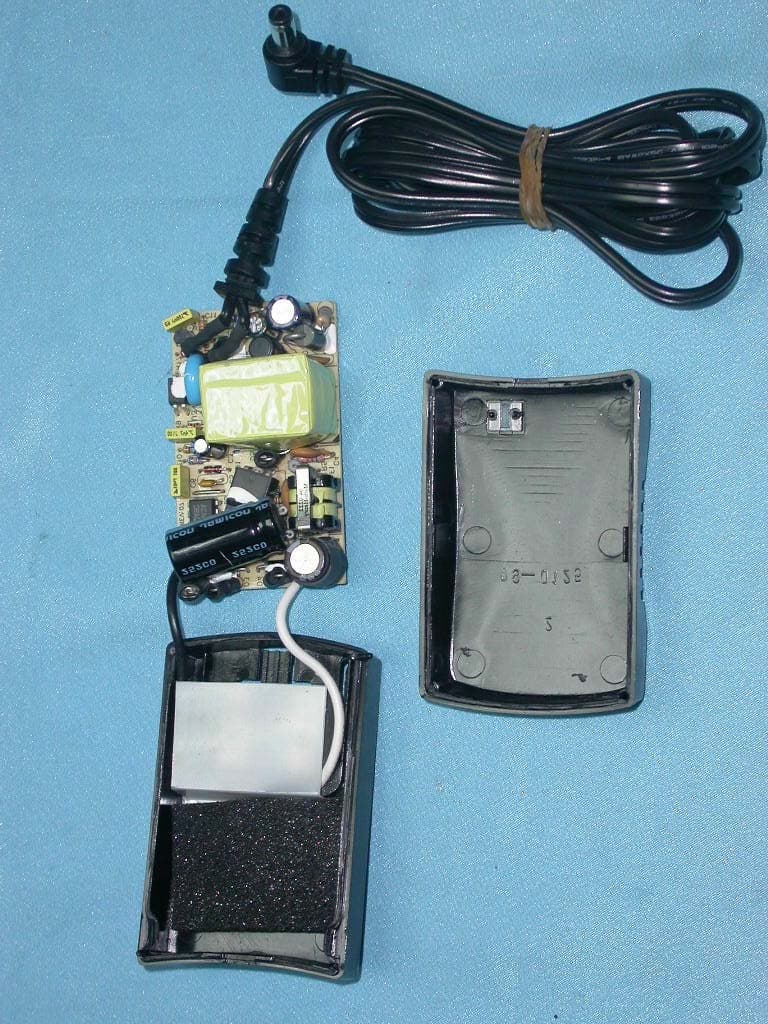
PKW-BEFW11S4V4
May 21, 2003Wireless Access Point Router
Equipment Class
DTS - Digital Transmission System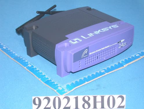
PKW-BEFW11S4V32
Apr 13, 2003Wireless Access Point Router with 4-Port Switch
Equipment Class
DTS - Digital Transmission System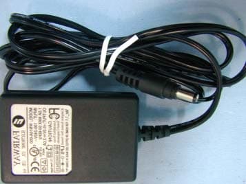
PKW-WSB24-2
Apr 03, 2003Wireless Signal Booster
Equipment Class
DTS - Digital Transmission System
PKW-BEFCMUH4
Apr 01, 2003Cable Gateway
Equipment Class
DTS - Digital Transmission System