PKW-WUSB12Wireless USB Adapter
Cisco-Linksys, LLC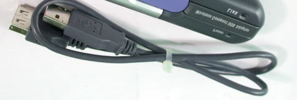
Click to zoom
Application Details
- Equipment Class
- DSS - Part 15 Spread Spectrum Transmitter
- Date of Grant
- Sep 17, 2002
- Application Purpose
- Original Equipment
- Date of Application
- Sep 16, 2002
- Equipment Note
- Wireless USB Adapter
- Frequency Range
- 2412.00000000 - 2462.00000000
- Company
- Cisco-Linksys, LLC
- Country
- United States
Documents & Files
Document Text
Text extracted from the exhibit documents filed with the FCC. Open a document above to read the original.
Users Manual
Instant Wireless TM Series Wireless Compact USB Adapter Use this guide to install:WUSB12 User Guide COPYRIGHT & TRADEMARKS Copyright © 2002 Linksys, All Rights Reserved. Instant Wireless is a trademark of Linksys.Linksys is a registered trademark of Linksys. Microsoft, Windows, and the Windows logo areregistered trademarks of Microsoft Corporation. All other trademarks and brand names are theproperty of their respective proprietors. LIMITED WARRANTY Linksys guarantees that every Instant Wir eless™ Wir eless Compact USB Adapter will be free from physical defects in material and workmanship under normal use for one year from thedate of purchase, when used within the limits set forth in the Specifications chapter of this UserGuide. If these products prove defective during this warranty period, call Linksys TechnicalSupport in order to obtain a Return Authorization Number. BE SURE TO HAVE YOUR PROOFOF PURCHASE AND A BARCODE FROM THE PRODUCT'S PACKAGING ON HAND WHENCALLING. RETURN REQUESTS CANNOT BE PROCESSED WITHOUT PROOF OF PUR-CHASE. When returning a product, mark the Return Authorization Number clearly on the out-side of the package and include a copy of your original proof of purchase. All customers locat-ed outside of the United States of America and Canada shall be held responsible for shippingand handling charges.IN NO EVENT SHALL LINKSYS’S LIABILITY EXCEED THE PRICE PAID FOR THE PRODUCTFROM DIRECT, INDIRECT, SPECIAL, INCIDENTAL, OR CONSEQUENTIAL DAMAGESRESULTING FROM THE USE OF THE PRODUCT, ITS ACCOMPANYING SOFTWARE, OR ITSDOCUMENTATION. LINKSYS DOES NOT OFFER REFUNDS FOR ANY PRODUCT. Linksysmakes no warranty or representation, expressed, implied, or statutory, with respect to its prod-ucts or the contents or use of this documentation and all accompanying software, and specif-ically disclaims its quality, performance, merchantability, or fitness for any particular purpose.Linksys reserves the right to revise or update its products, software, or documentation withoutobligation to notify any individual or entity. Please direct all inquiries to:Linksys P.O. Box 18558, Irvine, CA 92623. FCC STATEMENTThis Instant Wir eless™ Wir eless Compact USB Adapter has been tested and complies with the specifications for a Class B digital device, pursuant to Part 15 of the FCC Rules. These limits aredesigned to provide reasonable protection against harmful interference in a residential installa-tion. This equipment generates, uses, and can radiate radio frequency energy and, if not installedand used according to the instructions, may cause harmful interference to radio communications.However, there is no guarantee that interference will not occur in a particular installation. If thisequipment does cause harmful interference to radio or television reception, which is found byturning the equipment off and on, the user is encouraged to try to correct the interference by oneor more of the following measures:• Reorient or relocate the receiving antenna• Increase the separation between the equipment or devices• Connect the equipment to an outlet other than the receiver’s• Consult a dealer or an experienced radio/TV technician for assistanceFCC Caution: Any changes or modifications nor expressly approved by the party responsiblefor compliance could void the user's authority to operate this equipment.This device complies with Part 15 of the FCC Rules. Operation is subject to the following twoconditions: (1) This device may not cause harmful interference, and (2) This device mustaccept any interference received, including interference that may cause undesired operation.FCC RF Radiation Exposure StatementThis device and its antenna(s) must operate with a separation distance of at least 20 cm fromall persons using the cable provided and must not be co-located or operating in conjunctionwith any other antenna or transmitter. End-users must be provided with specific operations forsatisfying RF exposure compliance. UG-WUSB12-092002A JL Wireless Compact USB Adapter Table of ContentsChapter 1: Introduction 1 The Wireless Compact USB Adapter 1 Features 1 Package Contents 2 System Requirements 2 Chapter 2: Planning Your Wireless Network 3 Network Topology 3 Roaming 3 Chapter 3: About USB 5 Overview 5 USB Icon 5 USB Cabling 6 Chapter 4: Getting To Know the Wireless CompactUSB Adapter 7 The Wireless Compact USB Adapter’s Port and LEDs 7 Chapter 5: Software Installation and Configurationfor Windows 98SE, Me, and 2000 8 Overview 8 Instructions for Windows 98SE, Me, and 2000 9 Instant Wireless TM Series Chapter 6: Connecting the Wireless Compact USB Adapter 13 Hardware Detection for Windows 98SE, Me, and 2000 14 Chapter 7: Driver Installation and Configurationfor Windows XP 15 Overview 15 Driver Installation for Windows XP 15 Windows XP Wireless Zero Configuration 17 Chapter 8: Using the WLAN Monitor forWindows 98SE, Me, and 2000 19 Overview 19 Starting the WLAN Monitor 19 Link Information 20 Site Survey 21 Profiles 23 Creating a New Profile 25 Using the Expert Mode 32 Appendix A: Troubleshooting 38 Common Problems and Solutions 38 Frequently Asked Questions 38 Instant Wireless ™ Series Appendix B: Glossary 42 Appendix C: Specifications 47 Environmental 48 Appendix D: Warranty Information 49 Appendix E: Contact Information 50 Wireless Compact USB AdapterChapter 1: Introduction Add your PC to your wireless network the easy way—with the WirelessCompact USB Adapter. It’s so easy to install—simply connect the CompactAdapter to your PC’s USB port, click open the antenna, and run the LinksysSetup Wizard. Your PC is ready to share high-speed Internet access, files, andprinters through the network—without wires.The Adapter’s compact design and hot-swappable flexibility are tremendousadvantages for notebook users. Take the pocket-sized Adapter wherever you go.When you want to join a wireless network, install the Adapter on the fly—noneed to reboot. The Adapter draws power from the PC, so you don’t need anexternal power supply.Trans…
Text truncated - open the document above for the full version.
Users Manual
Instant Wireless TM Series Wireless Compact USB Adapter Use this guide to install:WUSB12 User Guide C O P Y R IG H T & TR ADE MAR K S C opyright © 2002 L inks ys , All R ights R es erved. Ins ta nt W ir eles s is a tra dema rk of L inks ys . L inks ys is a r egis ter ed tra dema rk of L inks ys . Mic r os oft, W indows , a nd the W indows logo a r e r egis ter ed tra dema rks of Mic r os oft C orpora tion. All other tra dema rks a nd bra nd na mes a r e the pr oper ty of their r es pec tive pr oprietors . L IMITE D W AR R AN TY L inks ys gua ra ntees tha t ever y Ins ta nt W ir eles s ™ W i r eles s C ompa c t U S B Ada pter will be fr ee fr om phys ic a l defec ts in ma teria l a nd workma ns hip under nor ma l us e for one yea r fr om the da te of pur c ha s e, when us ed within the limits s et for th in the S pec ific a tions c ha pter of this U s er G uide. If thes e pr oduc ts pr ove defec tive during this wa rra nty period, c a ll L inks ys T ec hnic a l S uppor t in or der to obta in a R etur n Authoriz a tion N umber . B E S U R E TO H A VE Y O U R P R O O F O F P U R C H AS E AN D A B AR C O DE F R O M TH E P R O DU C T'S P AC K AG IN G O N H AN D W H E N C AL L IN G . R E TU R N R E Q U E S TS C AN N O T B E P R O C E S S E D W ITH O U T P R O O F O F P U R - C H AS E . W hen r etur ning a pr oduc t, ma rk the R etur n Authoriz a tion N umber c lea rly on the out- s ide of the pa c ka ge a nd inc lude a c opy of your origina l pr oof of pur c ha s e. All c us tomers loc a t- ed outs ide of the U nited S ta tes of Americ a a nd C a na da s ha ll be held r es pons ible for s hipping a nd ha ndling c ha rges .IN N O E VE N T S H AL L L IN K S Y S ’S L IAB IL ITY E XC E E D TH E P R IC E P AID F O R TH E P R O DU C T F R O M DIR E C T , IN DIR E C T , S P E C IAL , IN C IDE N T AL , O R C O N S E Q U E N TIAL DAMAG E S R E S U L TIN G F R O M TH E U S E O F TH E P R O DU C T , ITS AC C O MP AN Y IN G S O F TW AR E , O R ITS DO C U ME N T A TIO N . L IN K S Y S DO E S N O T O F F E R R E F U N DS F O R AN Y P R O DU C T . L inks ys ma kes no wa rra nty or r epr es enta tion, expr es s ed, implied, or s ta tutor y , with r es pec t to its pr od- uc ts or the c ontents or us e of this doc umenta tion a nd a ll a c c ompa nying s oftwa r e, a nd s pec if- ic a lly dis c la ims its qua lity , per for ma nc e, mer c ha nta bility , or fitnes s for a ny pa r tic ula r purpos e. L inks ys r es erves the right to r evis e or upda te its pr oduc ts , s oftwa r e, or doc umenta tion without obliga tion to notify a ny individua l or entity . P lea s e dir ec t a ll inquiries to: L inks ys P . O . B ox 18558, Irvine, C A 92623. F C C S T A TE ME N T This Ins ta nt W ir eles s ™ W i r eles s C ompa c t U S B Ada pter ha s been tes ted a nd c omplies with the s pec ific a tions for a C la s s B digita l devic e, purs ua nt to P a r t 15 of the F C C R ules . Thes e limits a r e des igned to pr ovide r ea s ona ble pr otec tion a ga ins t ha r mful inter fer enc e in a r es identia l ins ta lla - tion. This equipment genera tes , us es , a nd c a n ra dia te ra dio fr equenc y energy a nd, if not ins ta lled a nd us ed a c c or ding to the ins truc tions , ma y c a us e ha r mful inter fer enc e to ra dio c ommunic a tions . H owever , ther e is no gua ra ntee tha t inter fer enc e will not oc c ur in a pa r tic ula r ins ta lla tion. If this equipment does c a us e ha r mful inter fer enc e to ra dio or televis ion r ec eption, whic h is found by tur ning the equipment of f a nd on, the us er is enc oura ged to tr y to c orr ec t the inter fer enc e by one or mor e of the following mea s ur es : • R eorient or r eloc a te the r ec eiving a ntenna • Inc r ea s e the s epa ra tion between the equipment or devic es • C onnec t the equipment to a n outlet other tha n the r ec eiver’ s • C ons ult a dea ler or a n experienc ed ra dio/TV tec hnic ia n for a s s is ta nc eF C C C a ution: Any c ha nges or modific a tions nor expr es s ly a ppr oved by the pa r ty r es pons ible for c omplia nc e c ould void the us er's a uthority to opera te this equipment.This devic e c omplies with P a r t 15 of the F C C R ules . O pera tion is s ubjec t to the following two c onditions : (1) This devic e ma y not c a us e ha r mful inter fer enc e, a nd (2) This devic e mus t a c c ept a ny inter fer enc e r ec eived, inc luding inter fer enc e tha t ma y c a us e undes ir ed opera tion. This tra ns mitter mus t not be c o-loc a ted or opera ting in c onjunc tion with a ny other a ntenna or tra ns mitter. r UG-WUSB12-091102A J L Wireless Compact USB Adapter Table of ContentsChapter 1: Introduction 1 The Wireless Compact USB Adapter 1 Features 1 Package Contents 2 System Requirements 2 Chapter 2: Planning Your Wireless Network 3 Network Topology 3 Roaming 3 Chapter 3: About USB 5 Overview 5 USB Icon 5 USB Cabling 6 Chapter 4: Getting To Know the Wireless CompactUSB Adapter 7 The Wireless Compact USB Adapter’s Port and LEDs 7 Chapter 5: Software Installation and Configurationfor Windows 98SE, Me, and 2000 8 Overview 8 Instructions for Windows 98SE, Me, and 2000 9 Instant Wireless TM Series Chapter 6: Connecting the Wireless Compact USB Adapter 13 Hardware Detection for Windows 98SE, Me, and 2000 14 Chapter 7: Driver Installation and Configurationfor Windows XP 15 Overview 15 Driver Installation for Windows XP 15 Windows XP Wireless Zero Configuration 17 Chapter 8: Using the WLAN Monitor forWindows 98SE, Me, and 2000 19 Overview 19 Starting the WLAN Monitor 19 Link Information 20 Site Survey 21 Profiles 23 Creating a New Profile 25 Using the Expert Mode 32 Appendix A: Troubleshooting 38 Common Problems and Solutions 38 Frequently Asked Questions 38 Instant Wireless ™ Series Appendix B: Glossary 42 Appendix C: Specifications 47 Environmental 48 Appendix D: Warranty Information 49 Appendix E: Contact Information 50 Wireless Compact USB AdapterChapter 1: Introduction Add your PC to your wireless network the easy way—with …
Text truncated - open the document above for the full version.
Cover Letter(s)
American Telecommunications Certification Body Inc. 6731 Whittier Ave, McLean, VA 22101 September 17, 2002 RE: Linksys Group, Inc. FCC ID: PKW-WUSB12 After a review of the submitted information, I have a few comments on the above referenced Application. 1) Please provide a photograph that shows the antenna. 2) This device may be directly plugged directly into any standard USB port. Other uses other than desktop computers (i.e. laptop use) becomes a portable RF Exposure condition. This condition exists because of the following: a) the antenna is integrated into the EUT b) If the device were to be directly plugged into the USB ports on a laptop, the antenna will be closer than the 20 cm distance if the user chooses to use the laptop in their lap. This same condition exists with PCMCIA Cards. However, this device appears to include a USB extension cable. This cable must be included with the product. Using this extension cable will ensure that the device will be used and installed in the proper manner. However, the users manual does not clearly instruct the user that this cable MUST be used. Sections of the manual that discuss the cable (section 3) and installation of the device (section 6) should clearly instruct the user that this cable must be used and how the device must be placed to meet the RF exposure requirements. Please provide an updated users manual. Timothy R. Johnson Examining Engineer mailto: [email protected] The items indicated above must be submitted before processing can continue on the above referenced application. Failure to provide the requested information may result in application termination. Correspondence should be considered part of the permanent submission and may be viewed from the Internet after a Grant of Equipment Authorization is issued. Please do not respond to this correspondence using the email reply button. In order for your response to be processed expeditiously, you must submit your documents through the AmericanTCB.com website. Also, please note that partial responses increase processing time and should not be submitted. Any questions about the content of this correspondence should be directed to the sender.
External Photos
Page 1 ANNEX PHOTOGRAPHS OF EUT Page 2 Page 3 Page 4
ID Label/Location Info
LABEL LOCATION FOR FCC ID
Internal Photos
Page 5 Page 6 Page 7 Page 8 Page 9
Internal Photos
Page 1 ANNEX PHOTOGRAPHS OF EUT Page 2 Page 3
Operational Description
FCC ID: PKW-WUSB12 ADT No.910814R06 Operational Description The transmitter of the EUT is powered by host equipment from USB port. The antenna is Dipole Antenna with UFL connector. Under normal use condition, the user has to keep at least 20cm separation distance between radiator and the body of the user. The other instruction, please have a look at the users manual. DSSS Information This device is Direct Sequence Spread Spectrum, the data is mixed by pseudorandom code which is an orthogonal code. The mixed data is digital modulated by BPSK and QPSK technique depends on the data rates. The CCK coding is applied for increasing the data rate, and also the processing gain will be increased. The bit rates are 1,2,5.5,11Mbps, the symbol rates are 1,1,1.375,1.375Mbps, the chip rates are always 11Mbps. So, the Chip/symbol is 11,11,8 and 8 respectively. Although is higher bit rate, the processing gain is lower than 10, but the CCK coding used in higher bit rate will provide 2.2dB coding gain.
RF Exposure Info
FCC ID: PKW-WUSB12 ADT No.: 910814R06 FCC TEST REPORT REPORT NO.: RF910814R06 MODEL NO.: WUSB12 ACCORDING: FCC Guidelines for Human Exposure IEEE C95.1 APPLICANT:The Linksys Group, INC. ADDRESS:17401 Armstrong Ave. Irvine, CA 92614 ISSUED BY:Advance Data Technology Corporation LAB LOCATION:47 14th Lin, Chiapau Tsun, Linko, Taipei, Taiwan, R.O.C. 0528 ILAC MRA Lab Code: 200102-0 FCC ID: PKW-WUSB12 ADT No.: 910814R06 RF Exposure Measurement (Mobile Device) 1. Introduction 2.4GHz frequency band is regarded specially as a dangerous band for its heating harmfulness to the human body. That’s why microwave oven is operating in this frequency band. The manufacturer whose product is working in this frequency band is obligatory to prove the harmfulness of his product. In this document, we try to prove the safety of radiation harmfulness to the human body for our product. The limit for Maximum Permissible Exposure (MPE) specified in FCC 1.1310 is followed. The Gain of the antenna used in this product is measured in a Fully Anechoic Chamber (FAC), and the maximum total power input to the antenna is measured. Through the Friis transmission formula and the maximum gain of the antenna, we can calculate the distance, away from the product, where the limit of MPE is reached. 2. Classification The antenna of the product, under normal use condition, is at least 20cm away from the body of the user. Warning statement for keeping 20cm separation distance and the prohibition of operating next to a person has been printed on the user’s manual. So, this product is classified as the Mobile Device. 3. RF Exposure Limit According to FCC 1.1310: The criteria listed in the following table shall be used to evaluate the environmental impact of human exposure to radio-frequency (RF) radiation as specified in 1.1307(b). FCC ID: PKW-WUSB12 ADT No.: 910814R06 LIMITS FOR MAXIMUM PERMISSIBLE EXPOSURE (MPE) Frequency Range (MHz) Electric Field Strength (V/m) Magnetic Field Strength (A/m) Power Density (mW/cm 2 ) Average Time (minutes) (A)Limits For Occupational / Control Exposures 30-30061.40.1631.06 300-1500......F/3006 1500-100,000......56 (B)Limits For General Population / Uncontrolled Exposure 30-30027.50.0730.230 300-1500......F/150030 1500-100,000......1.030 F = Frequency in MHz 4. Friis Formula Friis transmission formula : Pd = (Pout*G) / (4*pi*r 2 ) where Pd = power density in mW/cm 2 Pout = output power to antenna in mW G = gain of antenna in linear scale Pi = 3.1416 R = distance between observation point and center of the radiator in cm Pd is the limit of MPE, 1 mW/cm 2 . If we know the maximum Gain of the antenna and the total power input to the antenna, through the calculation, we will know the distance r where the MPE limit is reached. Ref. : David K. Cheng, Field and Wave Electromagnetics, Second Edition, Page 640, Eq. (11-133). 5. EUT Operating condition The software provided by Manufacturer enabled the EUT to transmit and receive data at lowest, middle and highest channel individually. FCC ID: PKW-WUSB12 ADT No.: 910814R06 6. Test Results 6.1 Antenna Gain The maximum Gain measured in Fully Anechoic Chamber is 1dBi or 1.26 (numeric). 6.2 Output Power Into Antenna & RF Exposure Distance : CHANNEL CHANNEL FREQUENCY (MHz) OUTPUT POWER TO ANTENNA (mW) MINIMUM ALLOWABLE DISTANCE ( r ) FROM SKIN (Centi-Meter) 1241227.671.66 6243726.301.62 11246226.611.63 The minimum allowable distance is very close to the enclosure of the antenna and is very far away from the human being under normal use condition.
RF Exposure Info
Test Report S/N: 111902-317PKW Test Date(s): December 17, 2002 FCC SAR Evaluation © 2002 Celltech Research Inc.1 of 21 . Celltech Research Inc. declares under its sole responsibility that this device was found to be in compliance with the Specific Absorption Rate (SAR) RF exposure requirements specified in FCC 47 CFR §2.1093. The device was tested in accordance with the measurement standards and procedures specified in FCC OET Bulletin 65, Supplement C, Edition 01-01 (General Population / Uncontrolled Exposure). I attest to the accuracy of data. All measurements were performed by me or were made under my supervision and are correct to the best of my knowledge and belief. I assume full responsibility for the completeness of these measurements and vouch for the qualifications of all persons taking them. This test report shall not be reproduced partially, or in full, without the prior written approval of Celltech Research Inc. The results and statements contained in this report pertain only to the device(s) evaluated. Russell Pipe Senior Compliance Technologist Celltech Research Inc. DECLARATION OF COMPLIANCE SAR EVALUATION Test Lab CELLTECH RESEARCH INC. Testing and Engineering Lab 1955 Moss Court Kelowna, B.C. Canada V1Y 9L3 Phone: 250-448-7047 Fax: 250-448-7046 e-mail: [email protected] web site: www.celltechlabs.com Applicant Information THE LINKSYS GROUP, INC. 17401 Armstrong Avenue Irvine, CA 92614 FCC Rule Part(s):47 CFR §2.1093 Test Procedure(s):FCC OET Bulletin 65, Supplement C (01-01) FCC Device Classification: Part 15 Spread Spectrum Transmitter (DSS) FCC ID:PKW-WUSB12 Model:WUSB12 Device Type:Wireless Compact USB LAN Adapter (for Laptop PC) Modulation:Direct Sequence Spread Spectrum (DSSS) Tx Frequency Range:2412 - 2462 MHz RF Output Power Tested:14.45 dBm Conducted (2412 MHz) 14.25 dBm Conducted (2437 MHz) 14.25 dBm Conducted (2462 MHz) Antenna Type:External Power Supply:from Host Laptop PC Host Laptop PC(s) Tested: 1. Gateway Solo 1400 (Vertical USB Slot) 2. SONY VAIO PCG-R505 Super Slim Pro (Horizontal USB Slot) Max. SAR Measured:0.407 W/kg (1g average) Test Report S/N: 111902-317PKW Test Date(s): December 17, 2002 FCC SAR Evaluation © 2002 Celltech Research Inc.2 of 21 TABLE OF CONTENTS 1.0INTRODUCTION..................................................................... 3 2.0DESCRIPTION OF EUT............................................................ 3 3.0SAR MEASUREMENT SYSTEM ............................................... 4 4.0MEASUREMENT SUMMARY..................................................... 5 5.0DETAILS OF SAR EVALUATION............................................... 6 6.0EVALUATION PROCEDURES................................................... 6-7 7.0SYSTEM PERFORMANCE CHECK............................................ 8 8.0EQUIVALENT TISSUES........................................................... 9 9.0SAR LIMITS........................................................................... 9 10.0SYSTEM SPECIFICATIONS...................................................... 10 11.0PROBE SPECIFICATION.......................................................... 11 12.0SAM PHANTOM...................................................................... 11 13.0DEVICE HOLDER.................................................................... 11 14.0TEST EQUIPMENT LIST........................................................... 12 15.0MEASUREMENT UNCERTAINTIES............................................ 13 16.0REFERENCES........................................................................ 14 APPENDIX A - SAR MEASUREMENT DATA............................................. 15 APPENDIX B - SYSTEM CHECK DATA.................................................... 16 APPENDIX C - SYSTEM VALIDATION..................................................... 17 APPENDIX D - PROBE CALIBRATION.................................................... 18 APPENDIX E - MEASURED FLUID DIELECTRIC PARAMETERS................ 19 APPENDIX F - SAM PHANTOM CERTIFICATE OF CONFORMITY.............. 20 APPENDIX G - SAR TEST SETUP & EUT PHOTOGRAPHS........................ 21 Test Report S/N: 111902-317PKW Test Date(s): December 17, 2002 FCC SAR Evaluation © 2002 Celltech Research Inc.THE LINKSYS GROUP, INC. FCC ID: PKW-WUSB123 of 21 Wireless USB LAN Adapter for Laptop PC (2412-2462MHz) 1.0 INTRODUCTION This measurement report demonstrates that THE LINKSYS GROUP, INC. Model: WUSB12 Wireless Compact USB LAN Adapter FCC ID: PKW-WUSB12 (for Laptop PC) complies with the RF exposure requirements specified in FCC 47 CFR §2.1093 (see reference [1]) for the General Population environment. The test procedures described in FCC OET Bulletin 65, Supplement C, Edition 01-01 (see reference [2]) were employed. A description of the product, operating configuration, detailed summary of the test results, methodology and procedures used in the evaluation, equipment used, and the various provisions of the rules are included within this test report. 2.0 DESCRIPTION of Equipment Under Test (EUT) FCC Rule Part(s)47 CFR §2.1093 Test ProcedureFCC OET Bulletin 65, Supplement C (01-01) FCC Device ClassificationPart 15 Spread Spectrum Transmitter (DSS) Device TypeWireless Compact USB LAN Adapter (for Laptop PC) FCC IDPKW-WUSB12 ModelWUSB12 Serial No.Pre-Production ModulationDirect Sequence Spread Spectrum (DSSS) Tx Frequency Range2412 - 2462 MHz RF Output Power Tested 14.45 dBm Conducted (2412 MHz) 14.25 dBm Conducted (2437 MHz) 14.25 dBm Conducted (2462 MHz) Antenna TypeExternal Power SupplyFrom Host Laptop PC Host Laptop PC(s) Tested 1. Gateway Solo 1400 (Vertical USB Slot) (S/N: BT002062449) 2. SONY VAIO PCG-R505 Super Slim Pro (Horizontal USB Slot) (S/N: 28321630 3205677) Test Report S/N: 111902-317PKW Test Date(s): December 17, 2002 FCC SAR Evaluation © 2002 Celltech Research Inc.THE LINKSYS GROUP, INC. FCC ID: PKW-WUSB124 of 21 Wireless USB LAN Adapter for Laptop PC (2412-2462MHz) 3.0 SAR MEASUREMENT SYSTEM Celltech Research SAR measurem…
Text truncated - open the document above for the full version.
Test Report
FCC ID: PKW-WUSB12 Report No.: RF910814R061Issued: Sept. 11, 2002 FCC TEST REPORT REPORT NO.: RF910814R06 MODEL NO.: WUSB12 RECEIVED: Aug. 14, 2002 TESTED: Aug. 1 ~ Aug. 23, 2002 APPLICANT:The Linksys Group, INC. ADDRESS:17401 Armstrong Ave. Irvine, CA 92614 ISSUED BY:Advance Data Technology Corporation LAB LOCATION:47 14th Lin, Chiapau Tsun, Linko, Taipei, Taiwan, R.O.C. This test report consists of 49 pages in total. It may be duplicated completely for legal use with the approval of the applicant. It should not be reproduced except in full, without the written approval of our laboratory. The client should not use it to claim product endorsement by CNLA, NVLAP or any government agencies. The test results in the report only apply to the tested sample. 0528 ILAC MRA Lab Code: 200102-0 FCC ID: PKW-WUSB12 Report No.: RF910814R062Issued: Sept. 11, 2002 Table of Contents 1CERTIFICATION...........................................................................................4 2SUMMARY OF TEST RESULTS...................................................................5 3GENERAL INFORMATION...........................................................................6 3.1GENERAL DESCRIPTION OF EUT..............................................................6 3.2DESCRIPTION OF TEST MODES................................................................7 3.3GENERAL DESCRIPTION OF APPLIED STANDARDS...............................7 3.4DESCRIPTION OF SUPPORT UNITS..........................................................8 4TEST TYPES AND RESULTS.......................................................................9 4.1CONDUCTED EMISSION MEASUREMENT................................................9 4.1.1LIMITS OF CONDUCTED EMISSION MEASUREMENT..............................9 4.1.2TEST INSTRUMENTS..................................................................................9 4.1.3TEST PROCEDURES.................................................................................10 4.1.4DEVIATION FROM TEST STANDARD.......................................................10 4.1.5TEST SETUP..............................................................................................11 4.1.6EUT OPERATING CONDITIONS................................................................12 4.1.7TEST RESULTS..........................................................................................13 4.2RADIATED EMISSION MEASUREMENT...................................................19 4.2.1LIMITS OF RADIATED EMISSION MEASUREMENT.................................19 4.2.2TEST INSTRUMENTS................................................................................20 4.2.3TEST PROCEDURES.................................................................................21 4.2.4DEVIATION FROM TEST STANDARD.......................................................21 4.2.5TEST SETUP..............................................................................................22 4.2.6EUT OPERATING CONDITIONS................................................................22 4.2.7TEST RESULTS..........................................................................................23 4.36dB BANDWIDTH MEASUREMENT..........................................................27 4.3.1LIMITS OF 6dB BANDWIDTH MEASUREMENT........................................27 4.3.2TEST INSTRUMENTS................................................................................27 4.3.3TEST PROCEDURE...................................................................................28 4.3.4DEVIATION FROM TEST STANDARD.......................................................28 4.3.5TEST SETUP..............................................................................................28 4.3.6EUT OPERATING CONDITIONS................................................................28 4.3.7TEST RESULTS..........................................................................................29 4.4MAXIMUM PEAK OUTPUT POWER..........................................................33 4.4.1LIMITS OF MAXIMUM PEAK OUTPUT POWER MEASUREMENT...........33 4.4.2INSTRUMENTS..........................................................................................33 4.4.3TEST PROCEDURES.................................................................................34 4.4.4DEVIATION FROM TEST STANDARD.......................................................34 4.4.5TEST SETUP..............................................................................................34 4.4.6EUT OPERATING CONDITIONS................................................................34 4.4.7TEST RESULTS..........................................................................................35 FCC ID: PKW-WUSB12 Report No.: RF910814R063Issued: Sept. 11, 2002 4.5POWER SPECTRAL DENSITY MEASUREMENT......................................36 4.5.1LIMITS OF POWER SPECTRAL DENSITY MEASUREMENT...................36 4.5.2TEST INSTRUMENTS................................................................................36 4.5.3TEST PROCEDURE................................…
Text truncated - open the document above for the full version.
Contact Information
Applicant
Ms Jennifer Yu(Associate Engineer)
Technical Contact
Advance Data Technology CorporationAlan Lane
[email protected]+886-3-327-0910
13-1, Lane 19, WenShan 3rd., St. · Taoyuan · Taiwan
Non-Technical Contact
Advance Data Technology CorporationAlan Lane
[email protected]+886-3-327-0910
Test Firm
Bureau Veritas CPS (H.K.) Ltd. Taoyuan BranchTommy Wu
Technical Specifications
| # | Rule Parts | Frequency Range | Power Output |
|---|---|---|---|
| 1 | 15C | 2.41 GHz - 2.46 GHz | 28.00 mW |
Other Applications from Cisco-Linksys, LLC

PKW-WMP54GV2
May 29, 2003Wireless-G PCI Adapter
Equipment Class
DTS - Digital Transmission System
PKW-BEFW11S4V4
May 21, 2003Wireless Access Point Router
Equipment Class
DTS - Digital Transmission System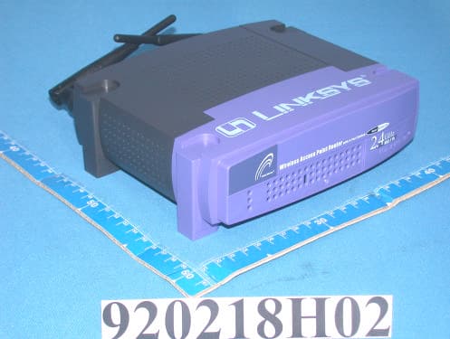
PKW-BEFW11S4V32
Apr 13, 2003Wireless Access Point Router with 4-Port Switch
Equipment Class
DTS - Digital Transmission System
PKW-WSB24-2
Apr 03, 2003Wireless Signal Booster
Equipment Class
DTS - Digital Transmission System
PKW-BEFCMUH4
Apr 01, 2003Cable Gateway
Equipment Class
DTS - Digital Transmission System