PLRAR225000Downstream Transmitter - Omnidirectional
Arcwave, Inc.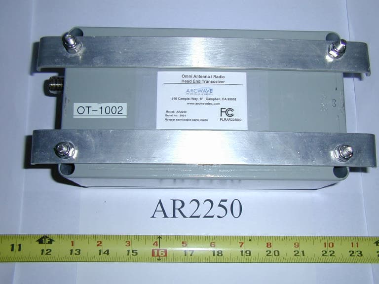
Click to zoom
Application Details
- Equipment Class
- DTS - Digital Transmission System
- Date of Grant
- Jan 13, 2004
- Application Purpose
- Original Equipment
- Date of Application
- Jan 13, 2004
- Equipment Note
- Downstream Transmitter - Omnidirectional
- Frequency Range
- 5729.00000000 - 5819.00000000
- Company
- Arcwave, Inc.
- Country
- United States
Documents & Files
Document Text
Text extracted from the exhibit documents filed with the FCC. Open a document above to read the original.
Users Manual
ARCell Planning and Installation Guide The ARCell License-Free Point-To-Multipoint Wireless Broadband Solution October 2003 © 2001-2003 Arcwave, Inc., 910 Campisi Way, Suite 1F, Campbell, CA 95008 USA Phone: 408-558-2300 www.arcwaveinc.com Customer Service: 408-748-7570 PN: 820-00001-002 LIMITED WARRANTY. Arcwave warrants to Buyer at the time of delivery that the equipment will be free from defects in material and workmanship under normal use and service. Arcwave's sole obligation under these warranties is limited to replacing or repairing, at its option, at its factory, any equipment that is returned to Arcwave, transportation, duties, and taxes prepaid, within twelve (12) months after delivery. In the case of products not of Arcwave's own manufacture, the only warranty available is that provided by the original equipment manufacturer. Arcwave shall return the equipment to Buyer freight prepaid. THIS WARRANTY IS EXPRESSED IN LIEU OF ALL OTHER WARRANTIES, EXPRESS, IMPLIED OR STATUTORY, INCLUDING THE IMPLIED WARRANTIES OF MERCHANTABILITY AND FITNESS FOR A PARTICULAR PURPOSE, AND OF ALL OTHER OBLIGATIONS OR LIABILITIES ON THE PART OF Arcwave, AND IT NEITHER ASSUMES NOR AUTHORIZES ANY OTHER PERSON TO ASSUME FOR ARCWAVEANY OTHER LIABILITIES IN CONNECTION WITH THE SALE OF PRODUCTS. IN NO EVENT WILL Arcwave BE LIABLE FOR CONSEQUENTIAL DAMAGES EVEN IF Arcwave HAS BEEN ADVISED OF THE POSSIBILITY OF SUCH DAMAGES. This Warranty does not apply to any of such products, which shall have been repaired or altered, except by Arcwave, or which shall have been subjected to misuse, negligence, or accident or operation outside the environmental specifications. Repairs or replacements of Equipment made during the warranty period or thereafter will be warranted, as provided above, for the remainder of the original warranty period or for ninety days from the date of return, as applicable, whichever is longer. RETURN OF EQUIPMENT UNDER WARRANTY: If an item of Equipment malfunctions or fails in normal intended usage and maintenance within the applicable Warranty Period: (a) The Customer shall promptly notify Arcwave of the problem and the serial number of the defective item; (b) Arcwave shall, at its sole option, either resolve the problem over the telephone or provide the Customer with a Returned Materials Authorization number (RMA #) and the address of the location to which the Customer may ship the defective item; (c) If the problem is not resolved over the telephone, the Customer shall attach a label to each returned item describing the fault and the Customer's return address. The Customer shall, at its cost, properly pack the item to be returned, prepay the insurance and shipping charges, and ship the item to the specified location; (d) If the Arcwave product shall prove to be defective in material or workmanship upon examination by Arcwave, Arcwave shall either repair or replace the returned item at its sole option. The replacement item may be new or refurbished; if refurbished, it shall be equivalent in operation to new Equipment. If Arcwave replaces a returned item, the Customer agrees that the returned item shall become the property of Arcwave. (e) Arcwave shall ship the repaired item or replacement to the Customer's return address by carrier and method of delivery chosen by Arcwave at its cost. If Customer has requested some other form of conveyance, such as express shipping, then the Customer shall pay the cost of return shipment. NOTE: This publication may include technical inaccuracies or typographical errors. Changes are periodically made to the information herein; these changes will be incorporated in new editions of this publication. Arcwave may make improvements and/or changes in the product(s) described in this publication at any time without notice. FCC NOTICE: This device complies with Part 15 of the FCC Rules. Operation is subject to the following two conditions: (1) this device may not cause harmful interference, and (2) this device must accept any interference received, including interference that may cause undesired operation. : ARCell and DBWA are Trademarks of Arcwave, Inc. DOCSIS is a registered trademark of Cable Television Laboratories, Inc. Other product and company names mentioned herein may be the trademarks of their respective owners. June 2003 ii FCC Requirements for Operation in the Unites States Radio Frequency Interference Warnings & Instructions This equipment has been tested and found to comply with the limits for a Class B digital device, pursuant to Part 15 of the FCC Rules. These limits are designed to provide reasonable protection against harmful interference in a residential installation. This equipment uses and can radiate radio frequency energy and, if not installed and used in accordance with the instructions, may cause harmful interference to radio communications. However, there is no guarantee that interference will not occur in a particular installation. If this equipment does cause harmful interference to radio or television reception, which can be determined by turning the equipment off and on, the user is encouraged to try to correct the interference by one or more of the following methods: • Reorient or relocate the receiving antenna • Increase the separation between the equipment and the receiver • Connect the equipment into an electrical outlet on a circuit different from that which the radio receiver is connected • Consult the dealer or an experienced radio/TV technician for help Modifications made to the product, unless expressly approved by Arcwave, Inc. could void the user’s right to operate the equipment. RF Exposure CAUTION: To ensure compliance with FCC RF exposure requirements, the antenna used for this device must be installed to provide a separation distance of at least 20 cm from all persons and must not be located or operated in conjunction with any other antenna or radio transmitter. Declaration Of Conformity We, Arcwave, Inc. 910 Campisi Way…
Text truncated - open the document above for the full version.
Users Manual
The incoming ground & DC- cable is attached to the bottom of the ground block along with ground leads to the negative bus on the fuse block and the enclosure’s ground lug. The incoming DC+ cable is attached to the bottom of the DC+ bus on the fuse block. Cables to the individual Hub antennas (light gray) terminate on the right side of the fuse block. The electrolytic capacitor (2200 uF) across the power supply busses reduces transients when individual Hub power connectors are inserted or removed with power ON. It is normally not needed, but if it is used, be sure to observe the polarity. Space is provided at the top of the box for additional lightning protectors, which have not proven to be necessary at our test site in San Jose, CA. Lightning protectors are installed on a ground bus in the base station equipment room to protect the indoor equipment. Upper power strip with barriers for sensing cable Ground bus Individual fuses Electrolytic capacitor Figure 5-8: Close-up of OJB. OJB Components The OJB pictured here is assembled from the following components: Device Vendor & Part Number Source Enclosure Hoffman A-1412CH Electric Supply Trade www.hoffmanonline.com Inner Panel Hoffman A14P12 Electric Supply Trade June 2003 Page 5-7 Fuse Block Blue Sea Systems 5015 West Marine Retail www.bluesea.com Ground Bus Blue Sea Systems 2301 West Marine Retail Dual Bus (use in lieu of fuse block) Blue Sea Systems 2702 West Marine Retail Rubber Insert ¾” couplings, locknuts, bushings Electric Supply Trade Shielded Cat 5 Cable Superior Essex BBDN Part #04-001-34 Graybar Electric Cat 5 Shield Bond Connectors Hubbell BC285SB Graybar Electric 5.3 Installation Detail – Indoor Equipment Figure 5-9 provides a single line diagram illustrating one Hub Transceiver. When implementing multiple sector systems, replicate the IF cabling, lightning protection, 12 dB test taps, etc. for each Hub Transceiver. June 2003 Page 5-8 1 12 d B Ta p W- C M T S Do w n st re a m p o r t Ne tw o r k po r t U p s t re a m p o rt 12 dB Ta p Up c o n v e r t e r Up s t r e a m IF fr o m Hu b T r a n s c e i ve r Do w n s t r e a m I F t o Hu b T r a n s c e i v e r Up s t r e a m p o r t i s ty p i c a l of 1 t o 6 10 0B a s e T t o / f r om Et h e r n e t S w i t c h an d I S P / I n t e r n e t AR C i S t a t i o n Co n t r o l l e r (f ut ur e ) Po s ( + ) Tr a n s c e i v e r Te l e m e t r y (f u t ur e ) B o nd G r o und Bu s t o R a c k DC Vo l t a g e Se ns e ( + ) ( - ) D C Po w e r Su ppl y Re m o t e V . S e n s e DC P o w e r t o Hu b Tr a n s c e i v e r s Ne g ( - ) Bo n d G r o u n d Bu s to F a c i l i ty G r o u n d N O T E : A l l G r o u nds t o be bo nd e d w i th # 6 A W G o r g r e a te r s t r a n d e d w i r e , o r w i t h g r ou n d st ra p of e q ui v a l e nt cr o s s s e c t i o n a r e a . B o nd G r o u nd B u s to a l l A R C i T r an s c ei v e r s an d M o un t i ng S t r u c t u r e s Gr o u n d B u s 1 2 34 L i gh tni n g P r o t e c to r Re f e r e n c e - Se e P a g e E 1 1 Figure 5-9: Connection diagram of indoor equipment. 5.3.1 Grounding and Lightning Protection Proper grounding is critical to the safety, performance and the life of the equipment installed at the base station. Refer to Figure 5-9. Arcwave recommends that the installer follow the general grounding practices employed in cellular and PCS base station sites. Arcwave recommends the following Lightning Protectors from PolyPhaser Corp. (www.polyphaser.com ). These PolyPhaser devices are designed to bolt directly to the ground bus. See diagram in Figure 5-9 for circled reference numbers. June 2003 Page 5-9 Table 5-1 – Lightning Protector Part Numbers Ref # Item Part # 1 75 ohm RG-6 transmit and receive cableIS-75F-C1 2 DC Power Supply IS-17VDC-30A-NG The ground bus, in turn, should be connected with an appropriate conductor (minimum #6 AWG) to the hub site ground that includes the power service and building common ground, per the NEC and local codes. Arcwave recommends the installer run a minimum #6 AWG conductor between the equipment room ground bus and a common ground point adjacent to the Hub Transceiver(s) unless the transceiver mounting system consists of a known low impedance ground (as a steel tower or monopole). In the case of a single sector Hub Transceiver installation, this point can be the antenna ground bolt or mounting bracket. In a multi sector installation including an outdoor junction box (OJB) this conductor can be connected to the ground bus in the OJB, which in turn, is connected to each transceiver and any nearby building or support structure ground. Normally the Wireless CMTS (W-CMTS), upconverter(s), DC power supply, 100baseT data switch, etc. are mounted in a 19-inch equipment rack in the base station equipment room. This rack should also be connected to the ground bus, preferably by a conductor #6 AWG or greater. When shielded cable is utilized to connect DC power between the hub equipment room and the hub antenna, ground the shield to the ground bus in the equipment room. Figures 5-10 and detail 5-11 show a ground bus installation with the specified PolyPhaser protector on each IF cable and on the antenna lead for a backhaul microwave. Note the ground strap to the right, which connects to the equipment rack. Lighting Protector for Backhaul Microwave Antenna Cable Ground strap to rack Ground wire from buildingGround bus bar Cable-Building entrance Figure 5-10: Example of Hub protection at building entrance. June 2003 Page 5-10 ARCell IF cables (3 downstream + 6 Upstream) Lightning protectors for ARCell IF cables Figure 5-11: Details of Fig 5-10 IF cable protection. 5.3.2 DC Power The Hub Transceiver requires 8.0 – 8.5 Vdc at the transceiver modules and draws approximately 900 mA of current. In a one or two sector installation a small variable voltage linear DC power supply capable of supplying at least 1000 mA is employed. Arcwave has successfully tested the following power supply in a one or two sector configu…
Text truncated - open the document above for the full version.
ID Label/Location Info
PROPOSED FCC ID LABEL AND LOCATION ARCWAVE, INC This device complies with Part 15 of the FCC Rules. Operation is subject to the following two conditions: (1) this device may not cause harmful interference, and (2) this device must accept any interference received, including interference that may cause undesired operation. FCC ID: PLRAR225000 FCC ID LABEL
Test Report
FCC CFR47 PART 15 SUBPART C CERTIFICATION TEST REPORT FOR DOWNSTREAM TRANSMITTER - OMNIDIRECTIONAL MODEL NUMBER: AR2250 FCC ID: PLRAR225000 REPORT NUMBER: 03U2037-5 ISSUE DATE: OCTOBER 2, 2003 Prepared for ARCWAVE INCORPORATED 910 CAMPISI WAY, #1C CAMPBELL, CALIFORNIA 95008 U.S.A Prepared by COMPLIANCE CERTIFICATION SERVICES 561F MONTEREY ROAD, MORGAN HILL, CA 95037, USA TEL: (408) 463-0885 FAX: (408) 463-0888 REPORT NO: 03U2037-5 DATE: OCTOBER 2, 2003 EUT: DOWNSTREAM TRANSMITTER - OMNIDIRECTIONAL FCC ID:PLRAR225000 Page 2 of 53 COMPLIANCE CERTIFICATION SERVICES DOCUMENT NO: CCSUP4031A 561F MONTEREY ROAD, MORGAN HILL, CA 95037 USA TEL: (408) 463-0885 FAX: (408) 463-0888 This report shall not be reproduced except in full, without the written approval of CCS. This document may be altered or revised by Compliance Certification Services personnel only, and shall be noted in the revision section of the document. TABLE OF CONTENTS 1. TEST RESULT CERTIFICATION.................................................................................................3 2. EUT DESCRIPTION.........................................................................................................................4 3. TEST METHODOLOGY..................................................................................................................5 4. FACILITIES AND ACCREDITATION..........................................................................................5 5. CALIBRATION AND UNCERTAINTY.........................................................................................6 5.1. MEASURING INSTRUMENT CALIBRATION............................................................................6 5.2. MEASUREMENT UNCERTAINTY..............................................................................................6 5.3. TEST AND MEASUREMENT EQUIPMENT...............................................................................7 6. SETUP OF EQUIPMENT UNDER TEST.......................................................................................8 7. APPLICABLE LIMITS AND TEST RESULTS...........................................................................10 7.1. 6 dB BANDWIDTH.....................................................................................................................10 7.2. 99% BANDWIDTH.....................................................................................................................14 7.3. PEAK OUTPUT POWER...........................................................................................................18 7.4. MAXIMUM PERMISSIBLE EXPOSURE...................................................................................22 7.5. AVERAGE POWER....................................................................................................................24 7.6. PEAK POWER SPECTRAL DENSITY.......................................................................................25 7.7. CONDUCTED SPURIOUS EMISSIONS...................................................................................29 7.8. RADIATED EMISSIONS............................................................................................................39 7.8.1. RADIATED EMISSIONS ABOVE 1 GHZ.......................................................................42 7.8.2. RADIATED EMISSIONS BELOW 1 GHZ......................................................................43 7.9. POWERLINE CONDUCTED EMISSIONS................................................................................45 8. SETUP PHOTOS..............................................................................................................................49 REPORT NO: 03U2037-5 DATE: OCTOBER 2, 2003 EUT: DOWNSTREAM TRANSMITTER - OMNIDIRECTIONAL FCC ID:PLRAR225000 Page 3 of 53 COMPLIANCE CERTIFICATION SERVICES DOCUMENT NO: CCSUP4031A 561F MONTEREY ROAD, MORGAN HILL, CA 95037 USA TEL: (408) 463-0885 FAX: (408) 463-0888 This report shall not be reproduced except in full, without the written approval of CCS. This document may be altered or revised by Compliance Certification Services personnel only, and shall be noted in the revision section of the document. 1. TEST RESULT CERTIFICATION COMPANY NAME: ARCWAVE, INC. 910 CAMPISI WAY, #1C CAMPBELL, CA 95008 U.S.A EUT DESCRIPTION: DOWNSTREAM TRANSMITTER - OMNIDIRECTIONAL MODEL: AR2250 DATE TESTED: SEPTEMBER 15 – OCTOBER 2, 2003 APPLICABLE STANDARDS STANDARD TEST RESULTS FCC PART 15 SUBPART C NO NON-COMPLIANCE NOTED Compliance Certification Services, Inc. tested the above equipment in accordance with the requirements set forth in the above standards. The test results show that the equipment tested is capable of demonstrating compliance with the requirements as documented in this report. Note: This document reports conditions under which testing was conducted and results of tests performed. This document may not be altered or revised in any way unless done so by Compliance Certification Services and all revisions are duly noted in the revisions section. Any alteration of this document not carried out by Compliance Certification Services will constitute fraud and shall nullify the document. Approved & Released For CCS By: Tested By: MIKE HECKROTTE NEELESH RAJ CHIEF ENGINEER EMC TECHNICIAN COMPLIANCE CERTIFICATION SERVICES COMPLIANCE CERTIFICATION SERVICES REPORT NO: 03U2037-5 DATE: OCTOBER 2, 2003 EUT: DOWNSTREAM TRANSMITTER - OMNIDIRECTIONAL FCC ID:PLRAR225000 Page 4 of 53 COMPLIANCE CERTIFICATION SERVICES DOCUMENT NO: CCSUP4031A 561F MONTEREY ROAD, MORGAN HILL, CA 95037 USA TEL: (408) 463-0885 FAX: (408) 463-0888 This report shall not be reproduced except in full, without the written approval of CCS. This document may be altered or revised by Compliance Certification Services personnel only, and shall be noted in the revision section of the document. 2. EUT DESCRIPTION The EUT is a transmitter operating in the 5725 – 5850 MHz band. The transmitter has a maximum peak conduct…
Text truncated - open the document above for the full version.
Test Setup Photos
REPORT NO: 03U2037-5 DATE: OCTOBER 2, 2003 EUT: DOWNSTREAM TRANSMITTER - OMNIDIRECTIONAL FCC ID:PLRAR225000 Page 49 of 53 COMPLIANCE CERTIFICATION SERVICES DOCUMENT NO: CCSUP4031A 561F MONTEREY ROAD, MORGAN HILL, CA 95037 USA TEL: (408) 463-0885 FAX: (408) 463-0888 This report shall not be reproduced except in full, without the written approval of CCS. This document may be altered or revised by Compliance Certification Services personnel only, and shall be noted in the revision section of the document. 8. SETUP PHOTOS ANTENNA PORT CONDUCTED RF MEASUREMENT SETUP ANTENNA PORT CONDUCTED PHOTO REPORT NO: 03U2037-5 DATE: OCTOBER 2, 2003 EUT: DOWNSTREAM TRANSMITTER - OMNIDIRECTIONAL FCC ID:PLRAR225000 Page 50 of 53 COMPLIANCE CERTIFICATION SERVICES DOCUMENT NO: CCSUP4031A 561F MONTEREY ROAD, MORGAN HILL, CA 95037 USA TEL: (408) 463-0885 FAX: (408) 463-0888 This report shall not be reproduced except in full, without the written approval of CCS. This document may be altered or revised by Compliance Certification Services personnel only, and shall be noted in the revision section of the document. RADIATED RF MEASUREMENT SETUP RADIATED FRONT PHOTO REPORT NO: 03U2037-5 DATE: OCTOBER 2, 2003 EUT: DOWNSTREAM TRANSMITTER - OMNIDIRECTIONAL FCC ID:PLRAR225000 Page 51 of 53 COMPLIANCE CERTIFICATION SERVICES DOCUMENT NO: CCSUP4031A 561F MONTEREY ROAD, MORGAN HILL, CA 95037 USA TEL: (408) 463-0885 FAX: (408) 463-0888 This report shall not be reproduced except in full, without the written approval of CCS. This document may be altered or revised by Compliance Certification Services personnel only, and shall be noted in the revision section of the document. RADIATED BACK PHOTO REPORT NO: 03U2037-5 DATE: OCTOBER 2, 2003 EUT: DOWNSTREAM TRANSMITTER - OMNIDIRECTIONAL FCC ID:PLRAR225000 Page 52 of 53 COMPLIANCE CERTIFICATION SERVICES DOCUMENT NO: CCSUP4031A 561F MONTEREY ROAD, MORGAN HILL, CA 95037 USA TEL: (408) 463-0885 FAX: (408) 463-0888 This report shall not be reproduced except in full, without the written approval of CCS. This document may be altered or revised by Compliance Certification Services personnel only, and shall be noted in the revision section of the document. POWERLINE CONDUCTED EMISSIONS MEASUREMENT SETUP LINE CONDUCTED FRONT PHOTO REPORT NO: 03U2037-5 DATE: OCTOBER 2, 2003 EUT: DOWNSTREAM TRANSMITTER - OMNIDIRECTIONAL FCC ID:PLRAR225000 Page 53 of 53 COMPLIANCE CERTIFICATION SERVICES DOCUMENT NO: CCSUP4031A 561F MONTEREY ROAD, MORGAN HILL, CA 95037 USA TEL: (408) 463-0885 FAX: (408) 463-0888 This report shall not be reproduced except in full, without the written approval of CCS. This document may be altered or revised by Compliance Certification Services personnel only, and shall be noted in the revision section of the document. END OF REPORT LINE CONDUCTED BACK PHOTO
Contact Information
Applicant
Leon Louie(Director of Operations)
Test Firm
Compliance Certification Services IncSteve Cheng
Technical Specifications
| # | Rule Parts | Frequency Range | Power Output |
|---|---|---|---|
| 1 | 15C | 5.73 GHz - 5.82 GHz | 106.00 mW |
Other Applications from Arcwave, Inc.
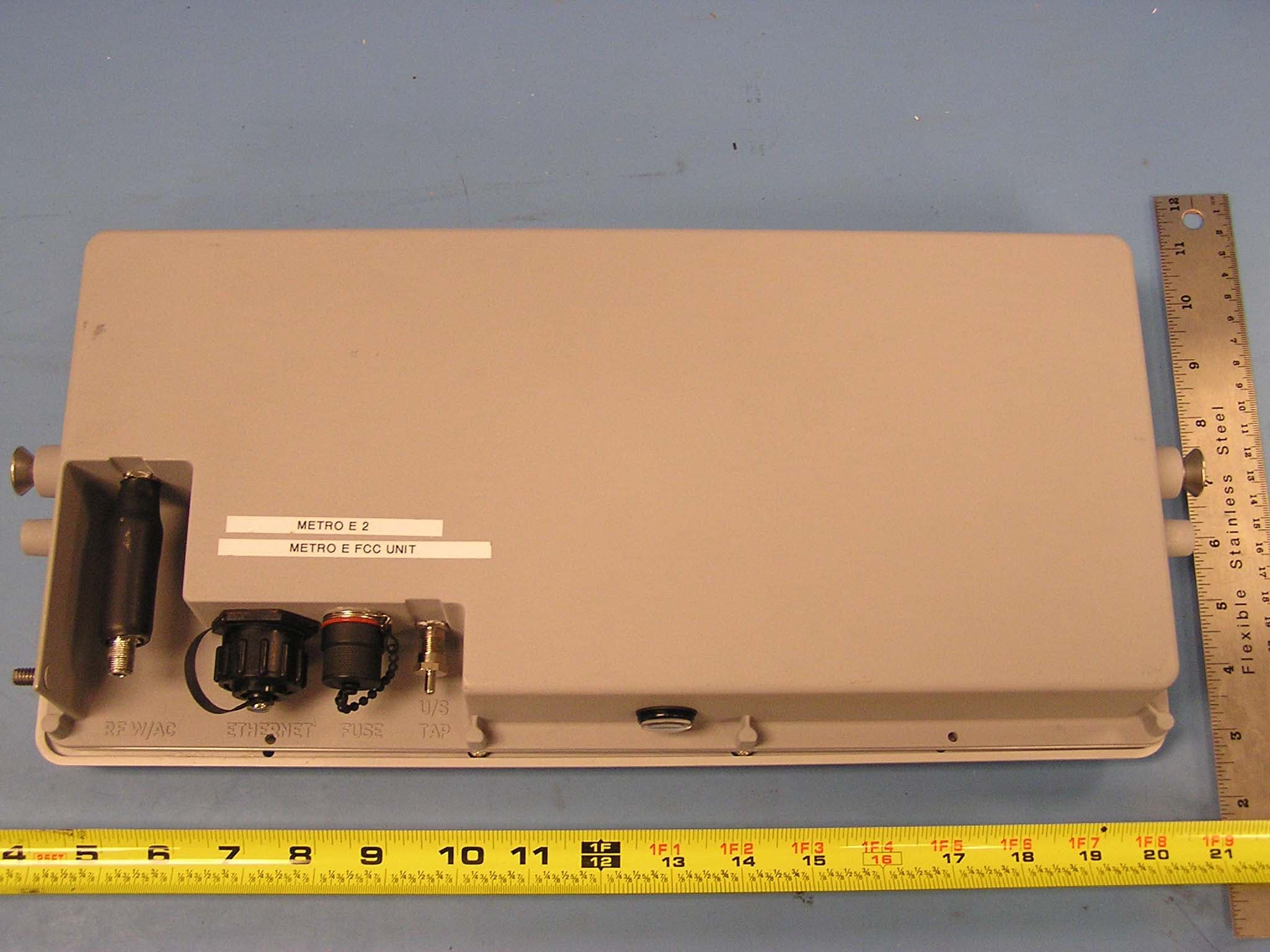
PLRFX501000
Sep 26, 2006Point-to-Point Wireless Internet System
Equipment Class
DTS - Digital Transmission System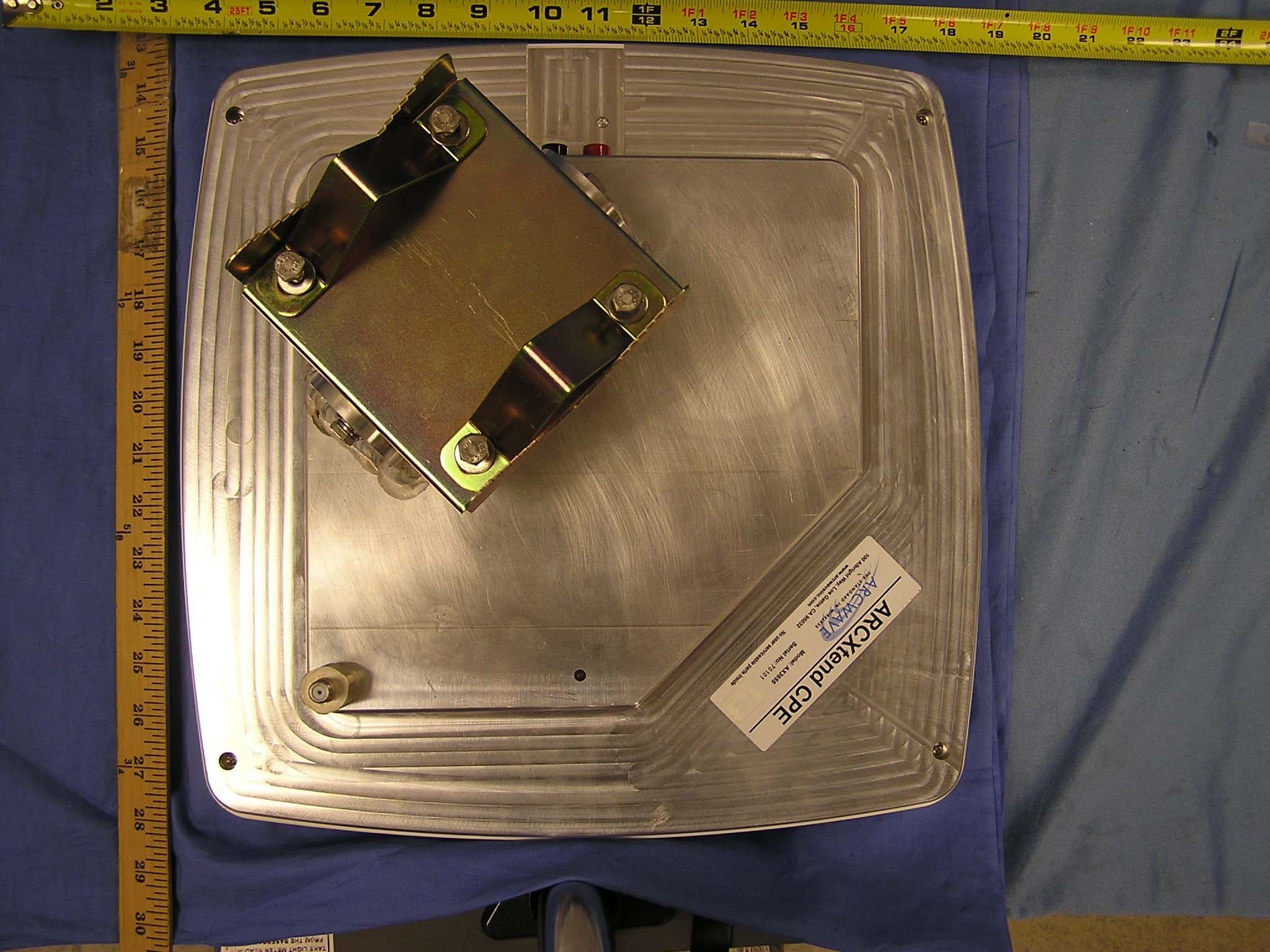
PLRAX365500
Jun 21, 2006Point to Multipoint Wireless Internet System
Equipment Class
DTS - Digital Transmission System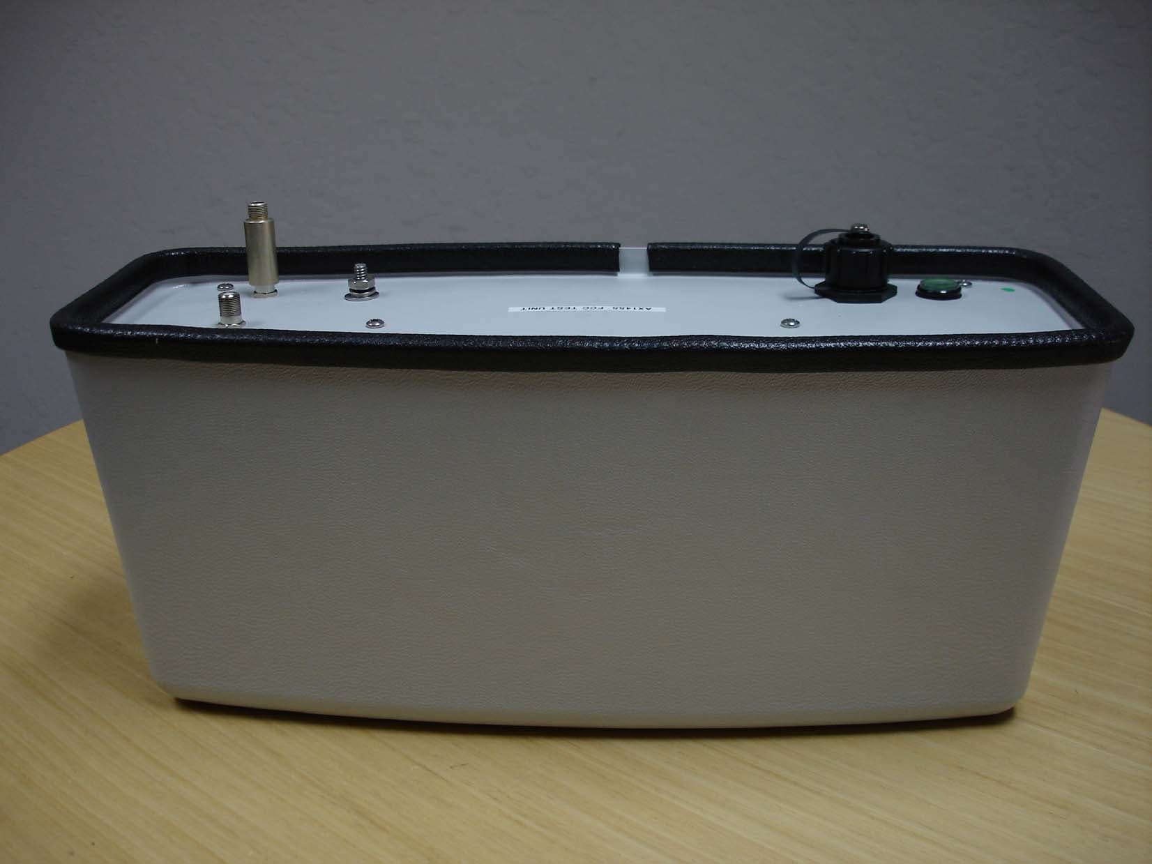
PLRAX145500
Sep 14, 2005ArcXtend TM
Equipment Class
DTS - Digital Transmission System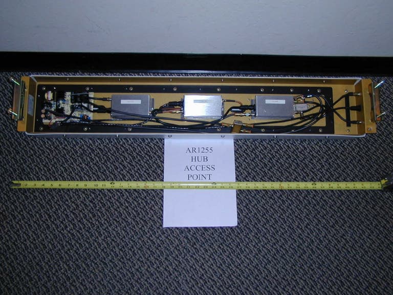
PLRARC12550
Jan 04, 2004Point To Multipoint Wireless System
Equipment Class
DTS - Digital Transmission System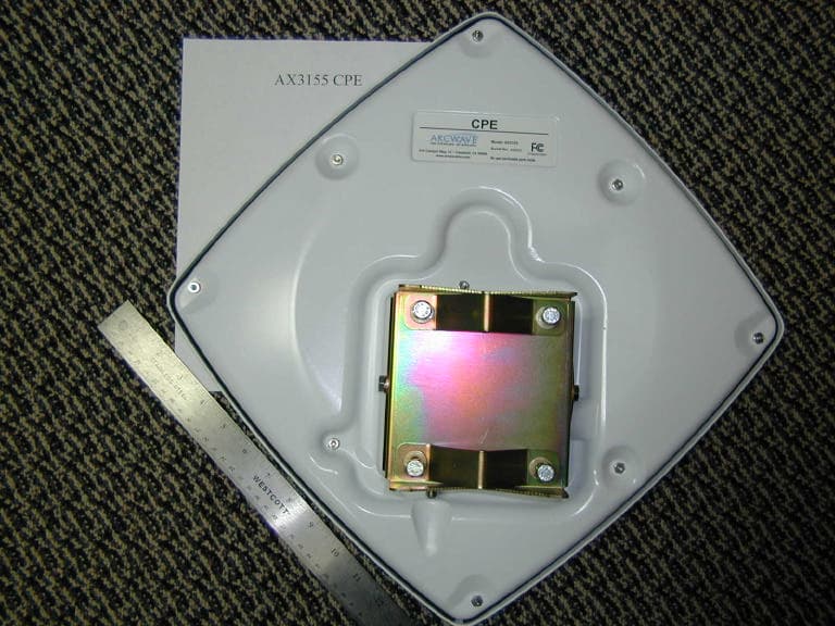
PLRAX315500
Dec 22, 2003Point To Multipoint Wireless System
Equipment Class
NII - Unlicensed National Information Infrastructure TX