PLRAX365500Point to Multipoint Wireless Internet System
Arcwave, Inc.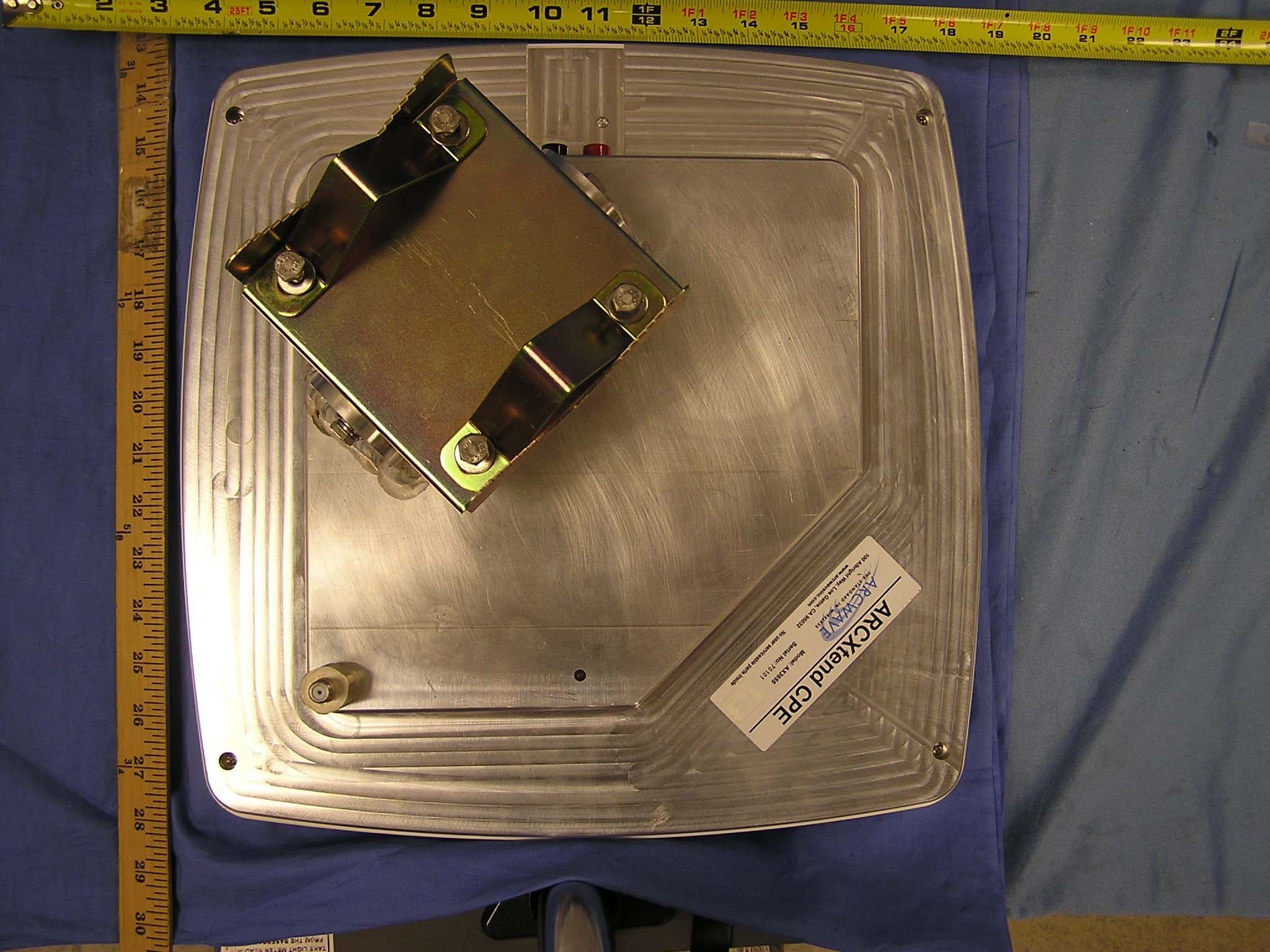
Click to zoom
Application Details
- Equipment Class
- DTS - Digital Transmission System
- Date of Grant
- Jun 21, 2006
- Application Purpose
- Original Equipment
- Date of Application
- Jun 21, 2006
- Equipment Note
- Point to Multipoint Wireless Internet System
- Frequency Range
- 5730.00000000 - 5760.00000000
- Company
- Arcwave, Inc.
- Country
- United States
Documents & Files
Document Text
Text extracted from the exhibit documents filed with the FCC. Open a document above to read the original.
Users Manual
Arcwave, Inc. 100 Albright Way, Suite A Los Gatos, CA 95032 USA, Phone: 408-558-2300 www.arcwaveinc.com © 2006 Arcwave’s ARCXtend HSD Enhanced 5.8 GHz Wireless Plant Extension Solution Installation Guide P/N: 920-00009-001 Rev. 1 Installation Guide 2 of 27 About this document This guide is designed familiarize you with the ARCXtend HSD Enhanced 5.8 GHz WPE solut ion. The guide ident ifies the major components and describes their funct ions wit hin the WPE solution. The installation and configuration processes are also discussed in fundamental terms. Revision History Related Documents The following documents provide additional information about the ARCXtend HSD WPE solution: • Arcwave’s ARCSmart 3.1 User Interface Guide • Arcwave Enterprise 3.1 MIB Specification Feedback We welcome your feedback on Arcwave documentation. This includes feedback on structure, content, accuracy, or completeness of our documents, and any other comments you may have. Please send your comments to [email protected]. Trademarks Arcwave and the Stylized Arcwave Logo, ARCXtend, ARCXtend HSD, ARCSmart, and PureBurst are trademarks of Arcwave. Other product/service names are the property of their owners. ISSUE # AUTHOR CHECK OUT CHECK IN COMMENTS 1.0 CM MARCH 6, 2006 FOR BETA RELEASE 1.1 CM MAY 23, 2006 ADDED ARCSMART 3.1 SUPPORT AND EXT BRACKET INFORMATION. Installation Guide 3 of 27 Notices The information in this publication is subject to change without notice. Arcwave shall not be liable for technical or editorial errors or omissions nor for any damages resulting from the use of this material. U.S. Federal Communication Commission (FCC) and Industry Canada (IC) Notification This device complies with part 15 of the U. S. FCC Rules and Regulations and with RSS- 210 of Industry Canada. Operation is subject to the following two conditions: (1) This device may not cause harmful interference, and (2) This device must accept any interference received, including interference that may cause undesired operation. In Canada, users should be cautioned to take note that high power radars are allocated as primary users (meaning they have priority) of 5250 – 5350 MHz and 5650 – 5850 MHz and these radars could cause interference and/or damage to license-exempt local area networks (LELAN). This equipment has been tested and found to comply with the limits for a Class B digital device, pursuant to Part 15 of the U.S. FCC Rules and with RSS-210 of Industry Canada. These limits are designed to provide reasonable protection against harmful interference in a residential installation. This equipment generates, uses, and can radiate radio-frequency energy and, if not installed and used in accordance with these instructions, may cause harmful interference to radio communications. If this equipment does cause harmful interference to radio or television reception, which can be determined by turning the equipment on and off, the user is encouraged to correct the interference by one or more of the following measures: Increase the separation between the affected equipment and the unit; Connect the affected equipment to a power outlet on a different circuit from that which the receiver is connected to; Consult the dealer and/or experienced radio/TV technician for help. Part 15, Section 15.21 Warning Changes or modifications not expressly approved by Arcwave, Inc. could void the user's authority to operate the equipment. FCC IDs and Industry Canada Certification Numbers are listed below: • FCC Identifier: • FCC Identifier: • IC Radio Cert. No.: Installation Guide 4 of 27 • IC Radio Cert. No.: RF Safety Warning To ensure compliance with FCC recommended General Population/Uncontrolled exposure limits the ARCXtend Hub and CPE must be installed at a minimum of one foot from areas frequented by the general population. To ensure compliance with FCC recommended Occupational/Controlled exposure limits, field engineers and technicians should maintain a minimum working distance of six inches, as measured from the front of the Hub or CPE to the front of their bodies. For working distance inside six inches, RF exposure should be limited to an average of 30 minutes at a time. All Arcwave equipment, however, has been designed to allow installation and maintenance at a range well within FCC RF exposure levels. DOCSIS Network Considerations Embedded Cable Modem Operation The ARCXtend Hub contains an embedded cable modem for remote management of the hub via the DOCSIS network, obtaining the DOCSIS operating parameters needed to program the hub and monitoring input RF signal level and quality. The embedded cable modem is identical in operation to a customer cable modem and requires Internet Protocol (IP) connectivity. Setup Prior to deployment of the ARCXtend solution, the embedded cable mode configuration file and firmware must be loaded on the TFTP server. The configuration and firmware files are included on the documentation CD shipped with each hub and can be downloaded from the Support Extranet, http://www.arcwaveinc.com/support.html . The configuration file provided by Arcwave contains the necessary modem specific informat ion required to do firmware downloads. Before an individual hub can be assigned an IP address its MAC address must be provisioned in the DHCP server. If the MAC address is not provisioned prior to deployment, most likely the embedded cable modem will receive a default configuration with Network Access set to “disable”. The Ethernet MAC address of the embedded cable modem is located on a label on the back o f each hub. Load Balancing Groups Currently, the ARCXtend solution does not support upstream shared spectrum (aka load balancing) groups where the cable modem(s) can be moved from one upstream frequency Installation Guide 5 of 27 to another based on plant conditions. Both the customer cable modem and the cable modem located inside the hub must be explicitly excluded from this feature. This is usually accomplished by putting the M…
Text truncated - open the document above for the full version.
Cover Letter(s)
1 Chris Harvey From: Claire Hoque [[email protected]] Sent: Tuesday, June 13, 2006 8:33 PM To: Chris Harvey; Chris Harvey Cc: Chuck Cowden; Erica Yueh; Michael Heckrotte Subject: answer: Arcwave, Inc. , FCC ID: PLRAX365500, Assessment NO.: AN06T5837, Notice#1 Attachments: 06U10203-3B FCC Report AX3655.pdf; AX3655 Theory of Operation(revised).pdf; FCC Label AX3655_Rev4.pdf; Installation Manual(revised).pdf; AX3655 Block Diagram(revised).pdf 06U10203-3B FCC Report AX3655.... AX3655 Theory of Operation(rev... FCC Label X3655_Rev4.pdf (123 Installation Manual(revised).p... AX3655 Block Dia gram(revised).... Hi Chris, Pls see answer below. 1. The test report 6dB bandwidth table has typos on the bandwidth measurements. The data in the 6dB bandwidth tables does not match the data on the associated plots. <answer> report is revised. 2. The test report documents channels of approximately 3MHz bandwidth (6dB plots), but the Installation Manual documents 1-30MHz channels (diagram on page 6 of 27). Please explain this discrepancy. <answer> manual is revised. 3. The Theory of Operation and Block Diagram exhibits document that the frequency of transmissions for this device is 5730 - 5762 MHz, where the test report documents transmission from 5730 - 5760 MHz. Please correct the discrepancy. <answer> theory of op. and block diagram are all revised. 4. Please explain why the Peak Power Measurements are slightly lower than the Average Measurements for the middle and high channels as documented in the test report. <answer>The altermate power measurement procedure was used in place of the Peak Power measurement procedure and the spurious emissions specification was changed to -30 dBc in accordance with the conditions for using the alternate procedure. This alternate procedure, also known as Maximum Conducted Power, generally yields a value that is slightly less than or equal to the average power measurement. This is an inherent property of the measurement procedure. FCC label is also revised to include necessary FCC statements. Thanks, Claire -----Original Message----- From: Chris Harvey Sent: Friday, June 09, 2006 6:26 AM To: Michael Heckrotte Cc: Chris Harvey; Claire Hoque Subject: Arcwave, Inc. , FCC ID: PLRAX365500, Assessment NO.: AN06T5837, Notice#1 Michael, You are listed as the technical contact for the above referenced TCB application. The following items need to be addressed before the review can be completed: 2 1. The test report 6dB bandwidth table has typos on the bandwidth measurements. The data in the 6dB bandwidth tables does not match the data on the associated plots. 2. The test report documents channels of approximately 3MHz bandwidth (6dB plots), but the Theory of Operation documents 1-30MHz channels (diagram on page 6 of 27). Please explain this discrepancy. 3. The Theory of Operation and Block Diagram exhibits document that the frequency of transmissions for this device is 5730 - 5762 MHz, where the test report documents transmission from 5730 - 5760 MHz. Please correct the discrepancy. 4. Please explain why the Peak Power Measurements are slightly lower than the Average Measurements for the middle and high channels as documented in the test report. The items indicated above must be submitted before processing can continue on the above referenced application. Failure to provide the requested information within 30 days of the original e-mail date may result in application dismissal and forfeiture of the filing fee. Also, please note that partial responses increase processing time and should not be submitted. Any questions about the content of this correspondence should be directed to the e-mail address listed below the name of the sender. Best regards, Chris Harvey [email protected]
Parts List/Tune Up Info
5Aug05 ArcExtend Antenna Parameters Antenna PolarizationGain Az Beamwidth El Beamwidth AX1655-ER 5.8GHz Hub Tx 20 deg Vertical 18 18 18 5.7GHz Hub Rx 20 deg RHCP 17 17 18 AX1655-EC 5.8GHz Hub Tx 60 deg Vertical 14 54 17 5.7GHz Hub Rx 60 deg RHCP 14 54 22 AX3655-VM 5.8GHz CPE Rx Vertical 21 10 10 5.7GHz CPE Tx RHCP 16 17 19 Max Linear GainVertical 15
Test Report
FCC CFR47 PART 15 SUBPART C CERTIFICATION TEST REPORT FOR POINT TO MULTIPOINT WIRELESS INTERNET SYSTEM MODEL NUMBER: AX3655-VM-12 FCC ID: PLRAX365500 REPORT NUMBER: 06U10203-1, Revision B ISSUE DATE: JUNE 13, 2006 Prepared for ARCWAVE, INC 100 ALBRIGHT WAY, SUITE A LOS GATOS, CA 95032, USA Prepared by COMPLIANCE CERTIFICATION SERVICES 561F MONTEREY ROAD MORGAN HILL, CA 95037, USA TEL: (408) 463-0885 FAX: (408) 463-0888 REPORT NO: 06U10203-3B DATE: JUNE 13, 2006 EUT: POINT TO MULTIPOINT WIRELESS INTERNET SYSTEM FCC ID: PLRAX365500 Page 2 of 53 COMPLIANCE CERTIFICATION SERVICES DOCUMENT NO: CCSUP4031A 561F MONTEREY ROAD, MORGAN HILL, CA 95037 USA TEL: (408) 463-0885 FAX: (408) 463-0888 This report shall not be reproduced except in full, without the written approval of CCS. Revision History Rev. Issue Date Revisions Revised By -- 5/5/06 Initial Issue MH B 6/13/06 Corrected Typos in Table on page 10 MH REPORT NO: 06U10203-3B DATE: JUNE 13, 2006 EUT: POINT TO MULTIPOINT WIRELESS INTERNET SYSTEM FCC ID: PLRAX365500 Page 3 of 53 COMPLIANCE CERTIFICATION SERVICES DOCUMENT NO: CCSUP4031A 561F MONTEREY ROAD, MORGAN HILL, CA 95037 USA TEL: (408) 463-0885 FAX: (408) 463-0888 This report shall not be reproduced except in full, without the written approval of CCS. TABLE OF CONTENTS 1. ATTESTATION OF TEST RESULTS............................................................................................. 4 2. TEST METHODOLOGY .................................................................................................................. 5 3. FACILITIES AND ACCREDITATION .......................................................................................... 5 4. CALIBRATION AND UNCERTAINTY.......................................................................................... 5 4.1. MEASURING INSTRUMENT CALIBRATION ............................................................................. 5 4.2. MEASUREMENT UNCERTAINTY ............................................................................................... 5 5. EQUIPMENT UNDER TEST............................................................................................................6 5.1. DESCRIPTION OF EUT ..............................................................................................................6 5.2. MAXIMUM OUTPUT POWER .................................................................................................... 6 5.3. SOFTWARE AND FIRMWARE .................................................................................................... 6 5.4. WORST-CASE CONFIGURATION AND MODE......................................................................... 6 5.5. DESCRIPTION OF TEST SETUP ................................................................................................ 7 6. TEST AND MEASUREMENT EQUIPMENT ................................................................................ 9 7. LIMITS AND RESULTS ................................................................................................................. 10 7.1. CHANNEL TESTS FOR THE 5725 TO 5850 MHz BAND ......................................................... 10 7.1.1. 6 dB BANDWIDTH ........................................................................................................... 10 7.1.2. 99% BANDWIDTH............................................................................................................ 14 7.1.3. PEAK OUTPUT POWER .................................................................................................. 18 7.1.4. MAXIMUM PERMISSIBLE EXPOSURE ........................................................................ 22 7.1.5. AVERAGE POWER........................................................................................................... 25 7.1.6. PEAK POWER SPECTRAL DENSITY ............................................................................ 26 7.1.7. CONDUCTED SPURIOUS EMISSIONS.......................................................................... 30 7.2. RADIATED EMISSIONS.............................................................................................................37 7.2.1. TRANSMITTER RADIATED SPURIOUS EMISSIONS ................................................. 37 7.2.2. TRANSMITTER ABOVE 1 GHz FOR 5725 TO 5850 MHz BAND ................................ 40 7.2.3. WORST-CASE RADIATED EMISSIONS BELOW 1 GHz ............................................. 41 7.3. POWERLINE CONDUCTED EMISSIONS ................................................................................ 45 8. SETUP PHOTOS .............................................................................................................................. 49 REPORT NO: 06U10203-3B DATE: JUNE 13, 2006 EUT: POINT TO MULTIPOINT WIRELESS INTERNET SYSTEM FCC ID: PLRAX365500 Page 4 of 53 COMPLIANCE CERTIFICATION SERVICES DOCUMENT NO: CCSUP4031A 561F MONTEREY ROAD, MORGAN HILL, CA 95037 USA TEL: (408) 463-0885 FAX: (408) 463-0888 This report shall not be reproduced except in full, without the written approval of CCS. 1. ATTESTATION OF TEST RESULTS COMPANY NAME: ARCWAVE, INC 100 ALBRIGH WAY, SUITE A LOS GATOS, CA 95032 U.S.A. EUT DESCRIPTION: POINT TO MULTIPOINT WIRELESS INTERNET SYSTEM MODEL: AX3655-VM-12 SERIAL NUMBER: 701010 DATE TESTED: MARCH 29 - MAY 5, 2006 APPLICABLE STANDARDS STANDARD TEST RESULTS FCC PART 15 SUBPART C NO NON-COMPLIANCE NOTED Compliance Certification Services, Inc. tested the above equipment in accordance with the requirements set forth in the above standards. The test results show that the equipment tested is capable of demonstrating compliance with the requirements as documented in this report. Note: The results documented in this report apply only to the tested sample, under the conditions and modes of operation as described herein. This document may not be altered or revised in any way unless done so by Compliance Certification Services and all revisions are duly noted in the …
Text truncated - open the document above for the full version.
Test Setup Photos
REPORT NO: 06U10203-3 DATE: MAY 5, 2006 EUT: POINT TO MULTIPOINT WIRELESS INTERNET SYSTEM FCC ID: PLRAX365500 Page 49 of 53 COMPLIANCE CERTIFICATION SERVICES DOCUMENT NO: CCSUP4031A 561F MONTEREY ROAD, MORGAN HILL, CA 95037 USA TEL: (408) 463-0885 FAX: (408) 463-0888 This report shall not be reproduced except in full, without the written approval of CCS. 8. SETUP PHOTOS ANTENNA PORT CONDUCTED RF MEASUREMENT SETUP ANTENNA PORT CONDUCTED PHOTO REPORT NO: 06U10203-3 DATE: MAY 5, 2006 EUT: POINT TO MULTIPOINT WIRELESS INTERNET SYSTEM FCC ID: PLRAX365500 Page 50 of 53 COMPLIANCE CERTIFICATION SERVICES DOCUMENT NO: CCSUP4031A 561F MONTEREY ROAD, MORGAN HILL, CA 95037 USA TEL: (408) 463-0885 FAX: (408) 463-0888 This report shall not be reproduced except in full, without the written approval of CCS. RADIATED RF MEASUREMENT SETUP RADIATED FRONT PHOTO REPORT NO: 06U10203-3 DATE: MAY 5, 2006 EUT: POINT TO MULTIPOINT WIRELESS INTERNET SYSTEM FCC ID: PLRAX365500 Page 51 of 53 COMPLIANCE CERTIFICATION SERVICES DOCUMENT NO: CCSUP4031A 561F MONTEREY ROAD, MORGAN HILL, CA 95037 USA TEL: (408) 463-0885 FAX: (408) 463-0888 This report shall not be reproduced except in full, without the written approval of CCS. RADIATED BACK PHOTO REPORT NO: 06U10203-3 DATE: MAY 5, 2006 EUT: POINT TO MULTIPOINT WIRELESS INTERNET SYSTEM FCC ID: PLRAX365500 Page 52 of 53 COMPLIANCE CERTIFICATION SERVICES DOCUMENT NO: CCSUP4031A 561F MONTEREY ROAD, MORGAN HILL, CA 95037 USA TEL: (408) 463-0885 FAX: (408) 463-0888 This report shall not be reproduced except in full, without the written approval of CCS. POWERLINE CONDUCTED EMISSIONS MEASUREMENT SETUP LINE CONDUCTED FRONT PHOTO REPORT NO: 06U10203-3 DATE: MAY 5, 2006 EUT: POINT TO MULTIPOINT WIRELESS INTERNET SYSTEM FCC ID: PLRAX365500 Page 53 of 53 COMPLIANCE CERTIFICATION SERVICES DOCUMENT NO: CCSUP4031A 561F MONTEREY ROAD, MORGAN HILL, CA 95037 USA TEL: (408) 463-0885 FAX: (408) 463-0888 This report shall not be reproduced except in full, without the written approval of CCS. END OF REPORT LINE CONDUCTED BACK PHOTO
Contact Information
Applicant
Leon Louie(Director of Operations)
Test Firm
Compliance Certification ServicesBarbara Judge
Technical Specifications
| # | Rule Parts | Frequency Range | Power Output |
|---|---|---|---|
| 1 | 15C | 5.73 GHz - 5.76 GHz | 110.00 mW |
Other Applications from Arcwave, Inc.
PLRFX501000
Sep 26, 2006Point-to-Point Wireless Internet System
Equipment Class
DTS - Digital Transmission System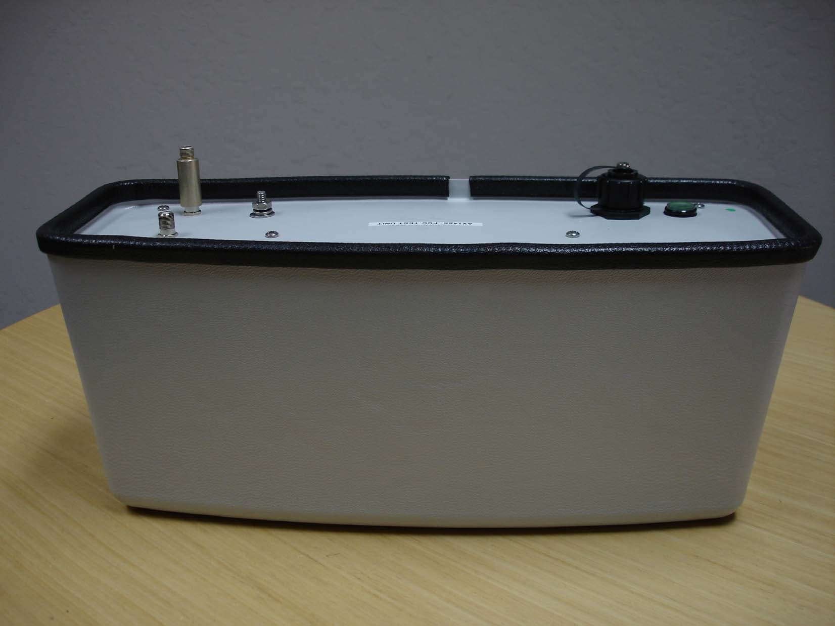
PLRAX145500
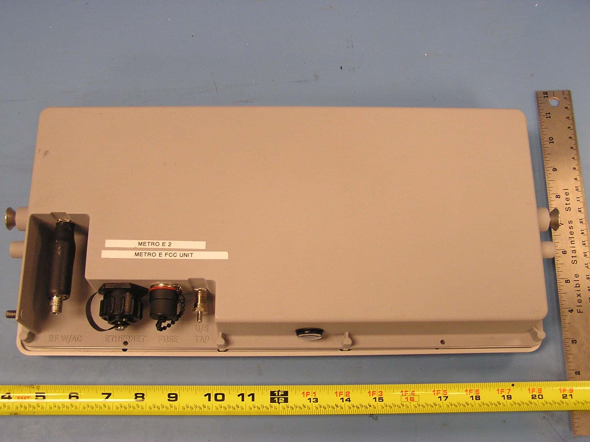
Sep 14, 2005ArcXtend TM
Equipment Class
DTS - Digital Transmission System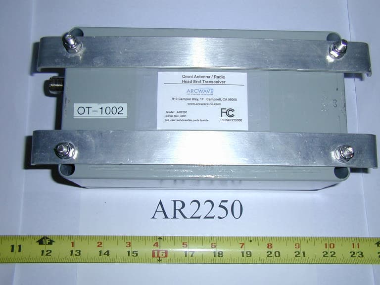
PLRAR225000
Jan 13, 2004Downstream Transmitter - Omnidirectional
Equipment Class
DTS - Digital Transmission System
PLRARC12550
Jan 04, 2004Point To Multipoint Wireless System
Equipment Class
DTS - Digital Transmission System
PLRAX315500
Dec 22, 2003Point To Multipoint Wireless System
Equipment Class
NII - Unlicensed National Information Infrastructure TX