PLRAX315500Point To Multipoint Wireless System
Arcwave, Inc.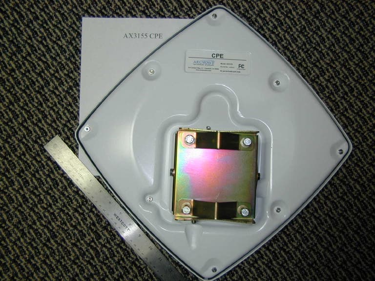
Click to zoom
Application Details
- Equipment Class
- NII - Unlicensed National Information Infrastructure TX
- Date of Grant
- Dec 22, 2003
- Application Purpose
- Original Equipment
- Date of Application
- Dec 22, 2003
- Equipment Note
- Point To Multipoint Wireless System
- Frequency Range
- 5260.00000000 - 5340.00000000
- Company
- Arcwave, Inc.
- Country
- United States
Documents & Files
Document Text
Text extracted from the exhibit documents filed with the FCC. Open a document above to read the original.
Users Manual
ARCXtend System Planning and Installation Guide A License-Free Point-To-Multipoint Wireless Cable Plant Extension Solution October 2003 © 2001-2003 Arcwave, Inc. 910 Campisi Way, Suite 1F, Campbell, CA 95008 USA, Phone: 408-558-2300 www.arcwaveinc.com Customer Service: 408-748-7570 [email protected] PN: 920-20003-001 LIMITED WARRANTY. Arcwave warrants to Buyer at the time of delivery that the equipment will be free from defects in material and workmanship under normal use and service. Arcwave's sole obligation under these warranties is limited to replacing or repairing, at its option, at its factory, any equipment that is returned to Arcwave, transportation, duties, and taxes prepaid, within twelve (12) months after delivery. In the case of products not of Arcwave's own manufacture, the only warranty available is that provided by the original equipment manufacturer. Arcwave shall return the equipment to Buyer freight prepaid. THIS WARRANTY IS EXPRESSED IN LIEU OF ALL OTHER WARRANTIES, EXPRESS, IMPLIED OR STATUTORY, INCLUDING THE IMPLIED WARRANTIES OF MERCHANTABILITY AND FITNESS FOR A PARTICULAR PURPOSE, AND OF ALL OTHER OBLIGATIONS OR LIABILITIES ON THE PART OF Arcwave, AND IT NEITHER ASSUMES NOR AUTHORIZES ANY OTHER PERSON TO ASSUME FOR ARCWAVEANY OTHER LIABILITIES IN CONNECTION WITH THE SALE OF PRODUCTS. IN NO EVENT WILL Arcwave BE LIABLE FOR CONSEQUENTIAL DAMAGES EVEN IF Arcwave HAS BEEN ADVISED OF THE POSSIBILITY OF SUCH DAMAGES. This Warranty does not apply to any of such products, which shall have been repaired or altered, except by Arcwave, or which shall have been subjected to misuse, negligence, or accident or operation outside the environmental specifications. Repairs or replacements of Equipment made during the warranty period or thereafter will be warranted, as provided above, for the remainder of the original warranty period or for ninety days from the date of return, as applicable, whichever is longer. RETURN OF EQUIPMENT UNDER WARRANTY: If an item of Equipment malfunctions or fails in normal intended usage and maintenance within the applicable Warranty Period: (a) The Customer shall promptly notify Arcwave of the problem and the serial number of the defective item; (b) Arcwave shall, at its sole option, either resolve the problem over the telephone or provide the Customer with a Returned Materials Authorization number (RMA #) and the address of the location to which the Customer may ship the defective item; (c) If the problem is not resolved over the telephone, the Customer shall attach a label to each returned item describing the fault and the Customer's return address. The Customer shall, at its cost, properly pack the item to be returned, prepay the insurance and shipping charges, and ship the item to the specified location; (d) If the Arcwave product shall prove to be defective in material or workmanship upon examination by Arcwave, Arcwave shall either repair or replace the returned item at its sole option. The replacement item may be new or refurbished; if refurbished, it shall be equivalent in operation to new Equipment. If Arcwave replaces a returned item, the Customer agrees that the returned item shall become the property of Arcwave. (e) Arcwave shall ship the repaired item or replacement to the Customer's return address by carrier and method of delivery chosen by Arcwave at its cost. If Customer has requested some other form of conveyance, such as express shipping, then the Customer shall pay the cost of return shipment. NOTE: This publication may include technical inaccuracies or typographical errors. Changes are periodically made to the information herein; these changes will be incorporated in new editions of this publication. Arcwave may make improvements and/or changes in the product(s) described in this publication at any time without notice. FCC NOTICE: This device complies with Part 15 of the FCC Rules. Operation is subject to the following two conditions: (1) this device may not cause harmful interference, and (2) this device must accept any interference received, including interference that may cause undesired operation. : ARCell, ARCXtend and DBWA are Trademarks of Arcwave, Inc. DOCSIS is a registered trademark of Cable Television Laboratories, Inc. Other product and company names mentioned herein may be the trademarks of their respective owners. ARCXtend manual, August 2003 ii FCC Requirements for Operation in the Unites States Radio Frequency Interference Warnings & Instructions This equipment has been tested and found to comply with the limits for a Class B digital device, pursuant to Part 15 of the FCC Rules. These limits are designed to provide reasonable protection against harmful interference in a residential installation. This equipment uses and can radiate radio frequency energy and, if not installed and used in accordance with the instructions, may cause harmful interference to radio communications. However, there is no guarantee that interference will not occur in a particular installation. If this equipment does cause harmful interference to radio or television reception, which can be determined by turning the equipment off and on, the user is encouraged to try to correct the interference by one or more of the following methods: • Reorient or relocate the receiving antenna • Increase the separation between the equipment and the receiver • Connect the equipment into an electrical outlet on a circuit different from that which the radio receiver is connected • Consult the dealer or an experienced radio/TV technician for help Modifications made to the product, unless expressly approved by Arcwave, Inc. could void the user’s right to operate the equipment. RF Exposure CAUTION: To ensure compliance with FCC RF exposure requirements, the antenna used for this device must be installed to provide a separation distance of at least 20 cm from all persons and must not be located or operated in conjunction with any other antenna or radio tran…
Text truncated - open the document above for the full version.
Users Manual
Figure 3-10: Pole Mount with temporary pivot bracket detail. It is often convenient to temporarily mount a spare pair of brackets below where the Access Point will be placed. This serves as a pivot point, as well as stopping slippage during installation, as in Figure 3-10. While downtilt is normally not needed, the nuts on either side of the Access Point’s “ears” also serve to establish downtilt. The following Figures 3-11 & 3-12 show the measurement, and the difference in the top and bottom measurements creates the downtilt. ARCXtend manual, August 2003 3-16 Figure 3-11: Measuring bottom spacing. Figure 3-12: Measuring top spacing. ARCXtend manual, August 2003 3-17 3.8.1 Bracket Mount There is a wide range of hardware vendors and approaches to mounting a pipe on a utility pole. For example, Valmont or RFS Celwave (Figures 3-13 & 3-14) will mount on the common wooden utility pole and any pipe of the proper OD can be clamped to it. Arcwave makes a bracket with the pipe welded to the bracket, which is simpler and lighter than the general purpose mounting kits. This was shown in the previous photographs. The industry has many variations on utility pole materials, e.g., metal & cement, and there are many solutions to mounting a pipe on those poles. The Vertical-Mount Access Point mounts on the pipe. Figure 3-13: Valmont Chain-Mount Pipe-Mount Kit combination. ARCXtend manual, August 2003 3-18 Figure 3-14: RFS Celwave Pole Brackets. 3.9 Strand Mount The majority of Access Points are expected to be mounted on the wire strand that supports the coaxial cable system. The strand-mount kit is designed to support a Horizontal-Mount Access Point. There is an arm at each end of the Horizontal Access Point. The top of the arm is clamped to the strand, as in Figure 3-15. The top of the arm is designed to slip in between the strand and the coaxial cable, which is usually spiral wrapped to the strand. ARCXtend manual, August 2003 3-19 Figure 3-15: Strand-mounted Access Point. In high-wind installations, the Access Point can be stabilized by clamping the bottom of the arm to a second strand. ARCXtend manual, August 2003 3-20 Figure 3-16: Strand Mount bracket detail. Figure 3-16 shows the detail of the strand mount bracket. ARCXtend manual, August 2003 3-21 Figure 3-17: Strand-mounted Access Point with dual clamping. 3.10 Verify Service Area When the Access Point is installed, its coverage should be verified by a sampling of building locations. ARCXtend manual, August 2003 3-22 4 Command Line Interface The ARCXtend has a Command Line Interface (CLI) function. The commands will be used by a technician in preparing an Access Point for service and field installation. Some technicians like to “burn-in” a unit prior to field deployment, and this burn-in period is a practical time to also pre-configure a unit via CLI for the parameters used in the network. 4.1 Physical Interface The physical interface is a four-wire EIA/TIA-485, which is a buss interface. The EIA/TIA-485 interface parameter settings are: 9600 baud, 8 bit, 1 stop bit, no parity, no flow control, local echo OFF. NOTE: Most PCs will require an RS-232 to EIA-485 converter. 4.2 Command Line Characteristics All valid commands are automatically saved as soon as they are accepted. Saved commands are not changed by power cycling (ON/OFF). All valid commands are echoed by the Module being addressed, so a technician can visually verify that the correct action has been taken. Commands or parameter values that are not used by the Module are refused (no change in settings) and echoed with the message: “Invalid Command/Parameter”, or a similar response, and a list of the acceptable input options. The “invalid” message is followed by the login response. Commands and parameters are NOT case sensitive. Commands have no spaces. Characters are 8-bit ASCII visible characters. Backspace is the only permitted invisible ASCII character. Login addresses for the Modules inside the Access Point are: 1. 01 = AR250 DX Module 2. 02 = AR150 TX Module 3. 03 = AR105 RX Module Commands that are common to all three modules are: 4. Login 5. Help 6. Quit 7. Banner ARCXtend manual, August 2003 4-1 8. Title 9. Initialize The system response and output is slightly different for each module, as will be explained. From/to tap (RF + Vac) V Power Pickoff Power Supply TXRXDX DX AR250 RX AR105 Receive Module TX AR150 Transmit Module RX & TX Antennas AC RF Control RS485 > Figure 4-1: Block Diagram AX1255 Access Point. 4.3 TX Command Line Interface The commands unique to the TX Module are: 1. Downstream Air Frequency 2. Downstream Enable These will be explained here. 4.3.1 TX Login The LOG Login command is required to establish one-to-one communications with a particular Module. Because this is a bussed system, one and only one Module can be active at any one time. Prior to the complete Login command, no responses or echo backs will occur. Once logged into one Module, one-to-one communications can occur. It is only necessary to log into a Module once to establish communications. *LOG<nnmm>, where nn = mm = {01, 02, ... 7F} is the hexadecimal address of the Module within the ARCell Transceiver/Antenna unit and is entered twice, i.e., nn and mm are identical. ARCXtend manual, August 2003 4-2 Note that the Login command begins with an asterisk (*), and the Module’s address is repeated twice. Prior to Login, no Module is active, and no character echo back will be received on the PC. Example, to log into the Transmit Module (AR150): Type: *log0202 (all of which is hidden because it is not echoed) AR150TX [02] (this is what the Module sends to indicate successful login) The information above echoed by the addressed Module is: the Module type (AR150), the function (TX = Transmitter), and the hex address (02). The LOG command will automatically make any other active Module Quit (logout) if it was previously enabled. 4.3.2 TX Downstream Air Frequency The Downstream Air center Frequency is set within th…
Text truncated - open the document above for the full version.
Cover Letter(s)
DEC-05-2003 16:04 RDVRNCED RRDIO CELLS 408 371 6934 P.03 ARCi 1255 Hub Outdoor Transceiver And CIE ARCi 3155 Subscriber Outdoor Transceiver FCC Theory of Operations .:tt:- ~ A)C3/~- ~ g The ARCi 1255 Hub Outdoor Transceiver and the ARCi 3155 Subscriber Outdoor Transcei~er operate together and in conjunction with DOCSIS1-based head end processor and modem equipment to provide high speed fixed wireless broadband Internet access. Together, these comprise a standalone IP network that is connected to the Internet through a gateway and/or router external to the ARCi system. Downstream Rackets (from the Internet to the user) are routed through the gateway to the DOCSIS head end processor where they are modulated onto a 6 MHz wide carrier centered at 44 MHz. This modulated continuous signal is translated by an adjacent upconverter to an intermediate frequency (IF) in the range of 481 to 571 MHz. The IF signal is transported over a coaxial cable (typically a premium grade of trade type RG6) to the rooftop or tower mounted 1255 Hub Outdoor Transceiver (Hub QT). The 1255 Hub aT, in turn, translates the signal to a frequency in the 5725 -5825 MHz UNW band, amplifies and radiates it via its integral flat panel transmit antenna. This 1255 hub transmit antenna has a 3 dB horizontal beam width of approximately 60 degrees and a 3 dB vertical beam width of approximately 10 degrees and employs linear vertical polarization. The system operator orients this antenna in the direction of his subscriber units. If a hub station configuration requires coverage in excess of sixty degrees of horizontal arc, multiple 1255 Hub OTs are employed. A telemetry feature of the 1255 Hub OT allows the system operator to monitor performance of the 1255 Hub OT in real time. A separate 2 pair cable run in parallel with the IF cable provides 8.5 volt DC power to the 1255 Hub OT and returns the telemetry information. The downstream packets transmitted by the 1255 Hub OT are received by the 3155 Subscriber Outdoor Transceiver (Sub aT) at the subscriber's location. The receiving antenna in the 3155 Sub OT has a 3 dB horizontal and vertical beamwidth of approximately ten degrees. The 3155 Sub OT translates the received signal from the 5725-5825 MHz band to an IF frequency between 429 and 519 MHz. This IF signal is transported over a coaxial cable (typically a premium grade of trade type RG6) to the subscriber DOCSIS modem. 1 Data Over Cable Service Interface Spedfication. DOCSIS is a trademark of Cable Television Laboratories, Inc. 2 Unlicensed National Information Infrastructure Page 1 of 3 ARCi CONFIDENTIAL INFORMATION 3/7/2002 DEC-05-2003 16:04 ADUANCED RADIO CELLS 408 371 6934 P.04 The modem, in turn, demodulates the downstream packets, performs forward error correction and sends the packets through its 10BaseT Ethernet interface to the subscriber's personal computer. In some cases an Ethernet hub or switch is employed to distribute the downstream packets to several personal computers. The 3155 Sub OT is powered by a small indoor cord-mounted power supply that provides 12 volts DC to a power inserter, which is a small passive devices that superimposes the DC power onto the IF signal cable between the modem and the 3155 Sub OT. :11:7 URstream Packets are sent from the subscriber's personal computer (directly or through an Ethernet hub or switch) to the 10BaseT Ethernet interface on the modem. The modem modulates these packets onto a 3.2 MHz wide IF carrier with center frequency in the range of 6.4 to 48.0 MHz. The carrier is enabled and disabled under the control of the DOCSIS head end processor via control packets embedded in the downstream transmission to the modem. This upstream IF signal from the modem is transported to the 3155 Sub OT on the same IF coaxial cable as the DC power and downstream signal. The 3155 Sub OT translates the IF signal to a frequency In the 5250 -5350 MHz UNII band, amplifies and radiates it towards the 1255 Hub OT via its integral flat panel antenna. The 3155 hub transmit antenna has both horizontal and vertical 3 dB beam widths of approximately 45 degrees and employs right hand circular polarization. The system operator orients this antenna in the direction of the 1255 Hub OT. At the hub site the 1255 Hub OT receives the upstream packets transmitted by the 3155 Sub OT. The receiving antenna in the 1255 Hub OT has a 3 dB horizontal beamwidth of approximately 55 degrees and 3 dB vertical beamwidth of approximately 3 degrees. The 1255 Hub OT translates the received signal from the 5250 -5350 MHz band to an IF frequency between 6.4 and 48.0 MHz. This IF signal is transported to the DOCSIS processor over a separate RG6 coaxial cable. The DOCSIS processor then routes the upstream packets to the Internet via the gateway/router. Note that the DOCSIS processor is the central controller of the network and performs many functions including addressing, buffering, timing, forward error correction, modulation, demodulation, etc. *« -7 Freauenc;yst~bi!i~ is assured by the use of 2.5 ppm TCXO-controlied synthesizers on all transmitters and receivers. In addition, the frequency of the upstream path is continuously monitored at the head end processor, and any needed correction commands are sent downstream to the cable modem in real Page 2 of 3 ARCi CONFIDENTIAL INFORMATION 3/7/2002 DEC-05-2003 16:04 RDURNCED RRDIO CELLS 408 371 6934 P.05 time. The frequency plan ensures that the transmitted signals are sufficiently far from the band edges so as not to overlap, even at the edges of the emission masks. Shutdown assurance is provided by different mechanisms for the downstream and the upstream. The downstream transmits a continuous TDMA signal that is monitored by all subscriber modems in the system. Thus, it is never shut down in normal operation. In the case of system maintenance shutdowns, powering off the DOCSIS head end processor removes its IF output signal. The 1255 Hub OT shuts off it RF transmission in the absence…
Text truncated - open the document above for the full version.
ID Label/Location Info
PROPOSED FCC ID LABEL AND LOCATION ARCWAVE, INC This device complies with Part 15 of the FCC Rules. Operation is subject to the following two conditions: (1) this device may not cause harmful interference, and (2) this device must accept any interference received, including interference that may cause undesired operation. FCC ID: PLRAX315500 FCC ID LABEL
RF Exposure Info
REPORT NO: 03U2037-7 DATE: OCTOBER 2, 2003 EUT: POINT TO MULTIPOINT WIRELESS SYSTEM FCC ID: PLRAX315500 Page 18 of 54 COMPLIANCE CERTIFICATION SERVICES DOCUMENT NO: CCSUP4031A 561F MONTEREY ROAD, MORGAN HILL, CA 95037 USA TEL: (408) 463-0885 FAX: (408) 463-0888 This report shall not be reproduced except in full, without the written approval of CCS. This document may be altered or revised by Compliance Certification Services personnel only, and shall be noted in the revision section of the document. 7.3. MAXIMUM PERMISSIBLE EXPOSURE LIMITS §15.247 (b) (5) Systems operating under the provisions of this section shall be operated in a manner that ensures that the public is not exposed to radio frequency energy levels in excess of the Commission's guidelines. See §1.1307(b)(1) of this chapter. CALCULATIONS Given E = √ (30 * P * G) / d and S = E ^ 2 / 3770 where E = Field Strength in Volts / meter P = Power in Watts G = Numeric antenna gain d = distance in meters S = Power Density in milliwatts / square centimeter Combining equations and rearranging the terms to express the distance as a function of the remaining variables yields: d = √ ((30 * P * G) / (3770 * S)) Changing to units of mW and cm, using: P (mW) = P (W) / 1000 and d (cm) =100 * d (m) yields d = 100 * √ ((30 * (P / 1000) * G) / (3770 * S)) d = 0.282 * √ (P * G / S) where d = distance in cm P = Power in mW G = Numeric antenna gain S = Power Density in mW / cm^2 REPORT NO: 03U2037-7 DATE: OCTOBER 2, 2003 EUT: POINT TO MULTIPOINT WIRELESS SYSTEM FCC ID: PLRAX315500 Page 19 of 54 COMPLIANCE CERTIFICATION SERVICES DOCUMENT NO: CCSUP4031A 561F MONTEREY ROAD, MORGAN HILL, CA 95037 USA TEL: (408) 463-0885 FAX: (408) 463-0888 This report shall not be reproduced except in full, without the written approval of CCS. This document may be altered or revised by Compliance Certification Services personnel only, and shall be noted in the revision section of the document. Substituting the logarithmic form of power and gain using: P (mW) = 10 ^ (P (dBm) / 10) and G (numeric) = 10 ^ (G (dBi) / 10) yields d = 0.282 * 10 ^ ((P + G) / 20) / √ S Equation (1) where d = MPE distance in cm P = Power in dBm G = Antenna Gain in dBi S = Power Density Limit in mW / cm^2 Equation (1) and the measured peak power is used to calculate the MPE distance. LIMITS S = 1.0 mW / cm^2 from 1.1310 Table 1 RESULTS No non-compliance noted: NOTE: For mobile or fixed location transmitters, the minimum separation distance is 20 cm, even if calculations indicate that the MPE distance would be less. Power Density LimitOutput PowerAntenna GainMPE Distance (mW/cm^2)(dBm)(dBi)(cm) 1.07.7014.003.43
Test Report
FCC CFR47 PART 15 SUBPART E CERTIFICATION TEST REPORT FOR POINT TO MULTIPOINT WIRELESS SYSTEM MODEL NUMBER: AX3155 FCC ID: PLRAX315500 REPORT NUMBER: 03U2037-7 ISSUE DATE: OCTOBER 2, 2003 Prepared for ARCWAVE INCORPORATED 910 CAMPISI WAY, #1C CAMPBELL, CALIFORNIA 95008 U.S.A Prepared by COMPLIANCE CERTIFICATION SERVICES 561F MONTEREY ROAD, MORGAN HILL, CA 95037, USA TEL: (408) 463-0885 FAX: (408) 463-0888 REPORT NO: 03U2037-7 DATE: OCTOBER 2, 2003 EUT: POINT TO MULTIPOINT WIRELESS SYSTEM FCC ID: PLRAX315500 Page 2 of 55 COMPLIANCE CERTIFICATION SERVICES DOCUMENT NO: CCSUP4031A 561F MONTEREY ROAD, MORGAN HILL, CA 95037 USA TEL: (408) 463-0885 FAX: (408) 463-0888 This report shall not be reproduced except in full, without the written approval of CCS. This document may be altered or revised by Compliance Certification Services personnel only, and shall be noted in the revision section of the document. TABLE OF CONTENTS 1. TEST RESULT CERTIFICATION.................................................................................................3 2. EUT DESCRIPTION.........................................................................................................................4 2.1. DESCRIPTION OF EUT..............................................................................................................4 2.2. DESCRIPTION OF ANTENNA....................................................................................................4 3. TEST METHODOLOGY..................................................................................................................6 4. FACILITIES AND ACCREDITATION..........................................................................................6 5. CALIBRATION AND UNCERTAINTY.........................................................................................7 5.1. MEASURING INSTRUMENT CALIBRATION............................................................................7 5.2. MEASUREMENT UNCERTAINTY..............................................................................................7 5.3. TEST AND MEASUREMENT EQUIPMENT...............................................................................8 6. SETUP OF EQUIPMENT UNDER TEST.......................................................................................9 7. APPLICABLE LIMITS AND TEST RESULTS...........................................................................11 7.1. EMISSION BANDWIDTH..........................................................................................................11 7.2. PEAK POWER............................................................................................................................15 7.3. MAXIMUM PERMISSIBLE EXPOSURE...................................................................................19 7.4. PEAK POWER SPECTRAL DENSITY.......................................................................................21 7.5. PEAK EXCURSION...................................................................................................................25 7.6. CONDUCTED SPURIOUS EMISSIONS...................................................................................29 7.7. RADIATED EMISSIONS............................................................................................................33 7.7.1. RADIATED EMISSIONS ABOVE 1 GHZ.......................................................................36 7.7.2. RADIATED EMISSIONS BELOW 1 GHZ......................................................................45 7.8. POWERLINE CONDUCTED EMISSIONS................................................................................47 8. SETUP PHOTOS..............................................................................................................................51 REPORT NO: 03U2037-7 DATE: OCTOBER 2, 2003 EUT: POINT TO MULTIPOINT WIRELESS SYSTEM FCC ID: PLRAX315500 Page 3 of 55 COMPLIANCE CERTIFICATION SERVICES DOCUMENT NO: CCSUP4031A 561F MONTEREY ROAD, MORGAN HILL, CA 95037 USA TEL: (408) 463-0885 FAX: (408) 463-0888 This report shall not be reproduced except in full, without the written approval of CCS. This document may be altered or revised by Compliance Certification Services personnel only, and shall be noted in the revision section of the document. 1. TEST RESULT CERTIFICATION COMPANY NAME: ARCWAVE, INC. 910 CAMPISI WAY, #1C CAMPBELL, CA 95008 U.S.A EUT DESCRIPTION: POINT TO MULTIPOINT WIRELESS SYSTEM MODEL: AX3155 DATE TESTED: SEPTEMBER 15 – OCTOBER 2, 2003 APPLICABLE STANDARDS STANDARD TEST RESULTS FCC PART 15 SUBPART E NO NON-COMPLIANCE NOTED Compliance Certification Services, Inc. tested the above equipment in accordance with the requirements set forth in the above standards. The test results show that the equipment tested is capable of demonstrating compliance with the requirements as documented in this report. Note: This document reports conditions under which testing was conducted and results of tests performed. This document may not be altered or revised in any way unless done so by Compliance Certification Services and all revisions are duly noted in the revisions section. Any alteration of this document not carried out by Compliance Certification Services will constitute fraud and shall nullify the document. Approved and Released For CCS By: Tested By: MIKE HECKROTTE NEELESH RAJ CHIEF ENGINEER EMC TECHNICIAN COMPLIANCE CERTIFICATION SERVICES COMPLIANCE CERTIFICATION SERVICES REPORT NO: 03U2037-7 DATE: OCTOBER 2, 2003 EUT: POINT TO MULTIPOINT WIRELESS SYSTEM FCC ID: PLRAX315500 Page 4 of 55 COMPLIANCE CERTIFICATION SERVICES DOCUMENT NO: CCSUP4031A 561F MONTEREY ROAD, MORGAN HILL, CA 95037 USA TEL: (408) 463-0885 FAX: (408) 463-0888 This report shall not be reproduced except in full, without the written approval of CCS. This document may be altered or revised by Compliance Certification Services personnel only, and shall be noted in the revision section of the document. 2. EUT DESCRIPTI…
Text truncated - open the document above for the full version.
Test Setup Photos
REPORT NO: 03U2037-7 DATE: OCTOBER 2, 2003 EUT: POINT TO MULTIPOINT WIRELESS SYSTEM FCC ID: PLRAX315500 Page 50 of 54 COMPLIANCE CERTIFICATION SERVICES DOCUMENT NO: CCSUP4031A 561F MONTEREY ROAD, MORGAN HILL, CA 95037 USA TEL: (408) 463-0885 FAX: (408) 463-0888 This report shall not be reproduced except in full, without the written approval of CCS. This document may be altered or revised by Compliance Certification Services personnel only, and shall be noted in the revision section of the document. 8. SETUP PHOTOS ANTENNA PORT CONDUCTED RF MEASUREMENT SETUP ANTENNA PORT CONDUCTED PHOTO REPORT NO: 03U2037-7 DATE: OCTOBER 2, 2003 EUT: POINT TO MULTIPOINT WIRELESS SYSTEM FCC ID: PLRAX315500 Page 51 of 54 COMPLIANCE CERTIFICATION SERVICES DOCUMENT NO: CCSUP4031A 561F MONTEREY ROAD, MORGAN HILL, CA 95037 USA TEL: (408) 463-0885 FAX: (408) 463-0888 This report shall not be reproduced except in full, without the written approval of CCS. This document may be altered or revised by Compliance Certification Services personnel only, and shall be noted in the revision section of the document. RADIATED RF MEASUREMENT SETUP RADIATED FRONT PHOTO REPORT NO: 03U2037-7 DATE: OCTOBER 2, 2003 EUT: POINT TO MULTIPOINT WIRELESS SYSTEM FCC ID: PLRAX315500 Page 52 of 54 COMPLIANCE CERTIFICATION SERVICES DOCUMENT NO: CCSUP4031A 561F MONTEREY ROAD, MORGAN HILL, CA 95037 USA TEL: (408) 463-0885 FAX: (408) 463-0888 This report shall not be reproduced except in full, without the written approval of CCS. This document may be altered or revised by Compliance Certification Services personnel only, and shall be noted in the revision section of the document. RADIATED BACK PHOTO REPORT NO: 03U2037-7 DATE: OCTOBER 2, 2003 EUT: POINT TO MULTIPOINT WIRELESS SYSTEM FCC ID: PLRAX315500 Page 53 of 54 COMPLIANCE CERTIFICATION SERVICES DOCUMENT NO: CCSUP4031A 561F MONTEREY ROAD, MORGAN HILL, CA 95037 USA TEL: (408) 463-0885 FAX: (408) 463-0888 This report shall not be reproduced except in full, without the written approval of CCS. This document may be altered or revised by Compliance Certification Services personnel only, and shall be noted in the revision section of the document. POWERLINE CONDUCTED EMISSIONS MEASUREMENT SETUP LINE CONDUCTED FRONT PHOTO REPORT NO: 03U2037-7 DATE: OCTOBER 2, 2003 EUT: POINT TO MULTIPOINT WIRELESS SYSTEM FCC ID: PLRAX315500 Page 54 of 54 COMPLIANCE CERTIFICATION SERVICES DOCUMENT NO: CCSUP4031A 561F MONTEREY ROAD, MORGAN HILL, CA 95037 USA TEL: (408) 463-0885 FAX: (408) 463-0888 This report shall not be reproduced except in full, without the written approval of CCS. This document may be altered or revised by Compliance Certification Services personnel only, and shall be noted in the revision section of the document. END OF REPORT LINE CONDUCTED BACK PHOTO
Contact Information
Applicant
Leon Louie(Director of Operations)
Test Firm
Compliance Certification Services IncSteve Cheng
Technical Specifications
| # | Rule Parts | Frequency Range | Power Output |
|---|---|---|---|
| 1 | 15E | 5.26 GHz - 5.34 GHz | 6.00 mW |
Other Applications from Arcwave, Inc.
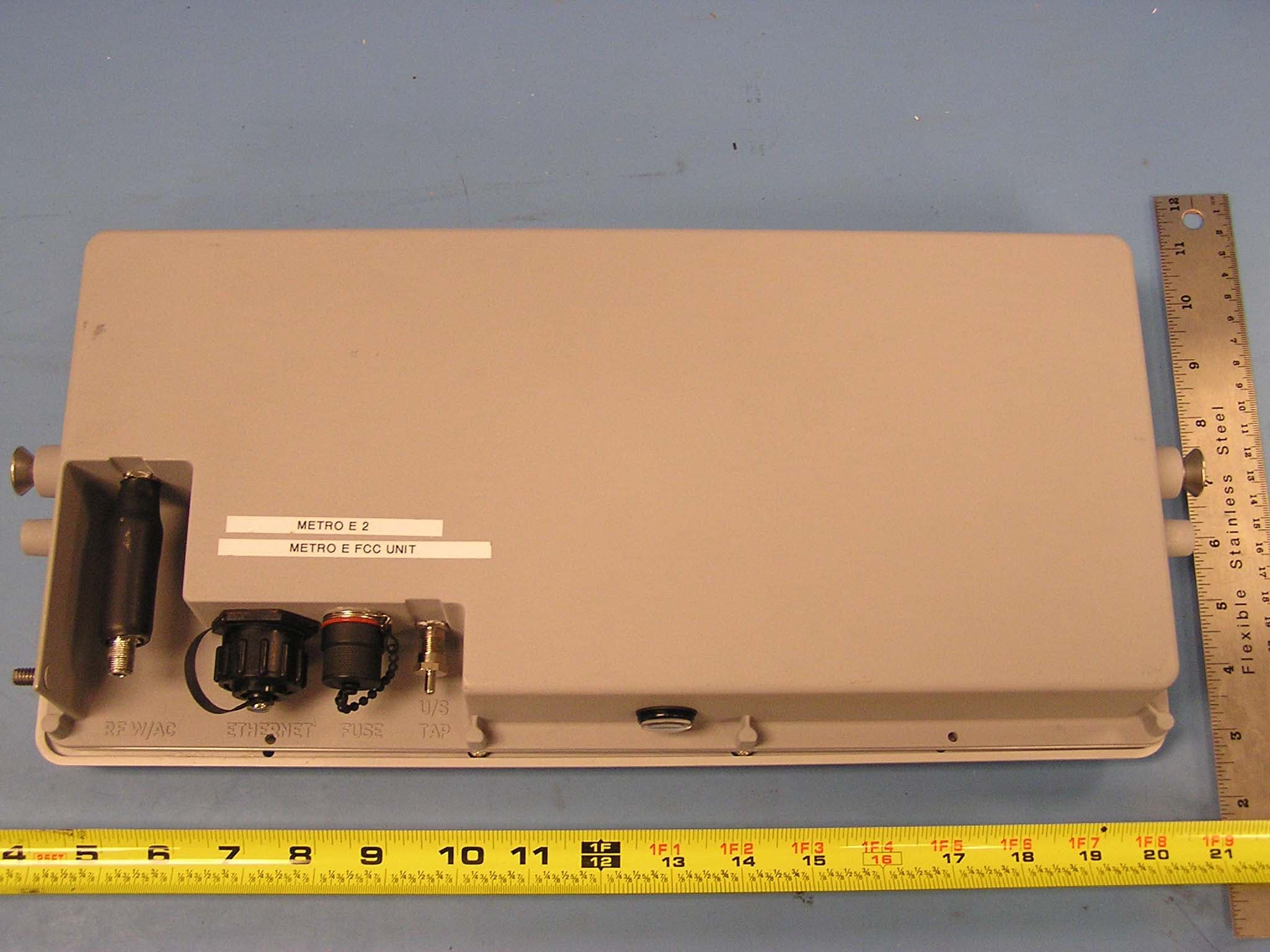
PLRFX501000
Sep 26, 2006Point-to-Point Wireless Internet System
Equipment Class
DTS - Digital Transmission System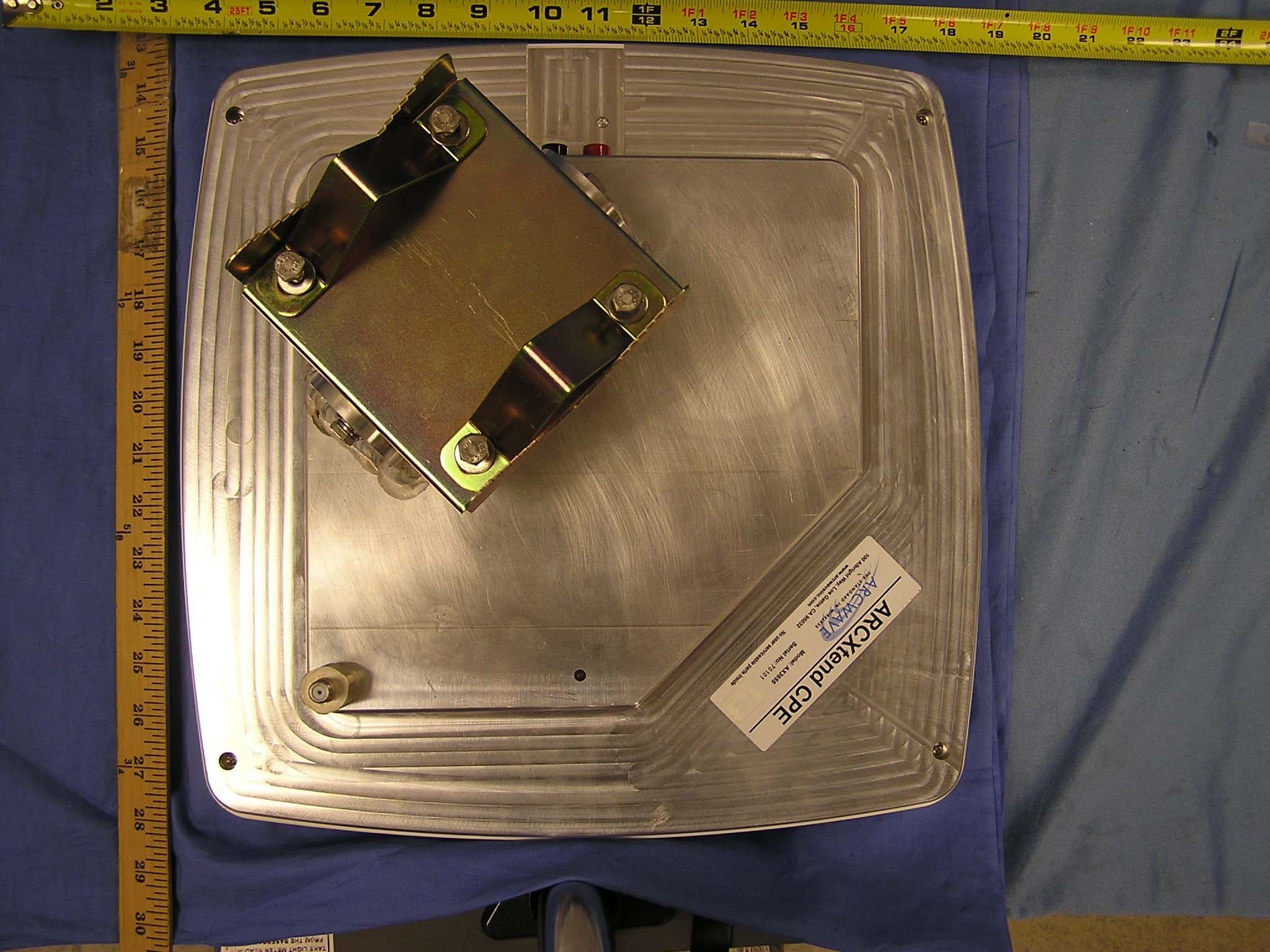
PLRAX365500
Jun 21, 2006Point to Multipoint Wireless Internet System
Equipment Class
DTS - Digital Transmission System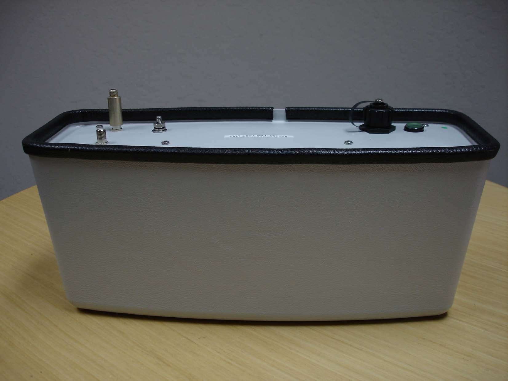
PLRAX145500
Sep 14, 2005ArcXtend TM
Equipment Class
DTS - Digital Transmission System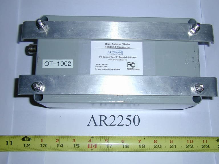
PLRAR225000
Jan 13, 2004Downstream Transmitter - Omnidirectional
Equipment Class
DTS - Digital Transmission System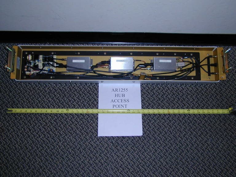
PLRARC12550
Jan 04, 2004Point To Multipoint Wireless System
Equipment Class
DTS - Digital Transmission System