PLRFX501000Point-to-Point Wireless Internet System
Arcwave, Inc.
Click to zoom
Application Details
- Equipment Class
- DTS - Digital Transmission System
- Date of Grant
- Sep 26, 2006
- Application Purpose
- Original Equipment
- Date of Application
- Sep 26, 2006
- Equipment Note
- Point-to-Point Wireless Internet System
- Frequency Range
- 5745.00000000 - 5825.00000000
- Company
- Arcwave, Inc.
- Country
- United States
Documents & Files
Document Text
Text extracted from the exhibit documents filed with the FCC. Open a document above to read the original.
Users Manual
Arcwave’s ARCXtend MetroE FX5010 Wireless Plant Extension Solution User Guide P/N: 920-20010-001 Rev. A 100 Albright Way, Suite A Los Gatos, CA 95032 USA, Phone: 408-558-2300 www.arcwaveinc.com © 2006 2 of 47 About this document This guide is designed familiarize you with the ARCXtend MetroE Wireless Plant Extension solution (WPE) solution and to provide basic instructions on the planning, provisioning, verification, monitoring and expansion of MetroE deployments. It is designed to be used on conjunction with the ARCView Mesh Management Software User Guide which provides detailed information on the Note The software used on the ARCXtend MetroE wireless plant extension solution supports not only point to point and point to multipoint but also mesh network topologies. The ARCView network management software uses the term ‘‘mesh’ for all configurations. For consistency this guide will also use the term mesh to describe any configuration of two or more MetroE nodes. A node refers to one radio which for the purpose of this guide is one MetroE radio. Again we will use node to refer to an MetroE radio for consistency with ARCView. Revision History Related Documents The following documents provide additional information about the ARCXtend HSD WPE solution: • ARCView Mesh Manaegment Sofwtare User Guide • ARCXtend MetroE MIB (.txt) Feedback We welcome your feedback on Arcwave documentation. This includes feedback on structure, content, accuracy, or completeness of our documents, and any other comments you may have. Please send your comments to [email protected]. Trademarks Arcwave and the Stylized Arcwave Logo, ARCXtend, ARCXtend MetroE, ARCView and ARCViewPro are trademarks of Arcwave. Other product/service names are the property of their owners. ISSUE # AUTHOR CHECK OUT CHECK IN COMMENTS 1.0 CM JUNE 7, 2006 FOR BETA RELEASE 3 of 47 Notices The information in this publication is subject to change without notice. Arcwave shall not be liable for technical or editorial errors or omissions nor for any damages resulting from the use of this material. U.S. Federal Communication Commission (FCC) Notification This device complies with part 15 of the U. S. FCC Rules and Regulations and which is subject to the following two conditions: (1) This device may not cause harmful interference, and (2) This device must accept any interference received, including interference that may cause undesired operation. This equipment has been tested and found to comply with the limits for a Class B digital device, pursuant to Part 15 of the U.S. FCC Rules. These limits are designed to provide reasonable protection against harmful interference in a residential installation. This equipment generates, uses, and can radiate radio-frequency energy and, if not installed and used in accordance with these instructions, may cause harmful interference to radio communications. If this equipment does cause harmful interference to radio or television reception, which can be determined by turning the equipment on and off, the user is encouraged to correct the interference by one or more of the following measures: Increase the separation between the affected equipment and the unit; • Connect the affected equipment to a power outlet on a different circuit from that which the receiver is connected to; • Consult the dealer and/or experienced radio/TV technician for help. Part 15, Section 15.21 Warning Changes or modifications not expressly approved by Arcwave, Inc. could void the user's authority to operate the equipment. FCC IDs Numbers are listed below: FCC Identifier: PLRFX501000 RF Safety Warning To ensure compliance with FCC recommended General Population/Uncontrolled exposure limits the ARCXtend MetroE radio must be installed at a minimum of one foot from areas frequented by the general population. To ensure compliance with FCC recommended Occupational/Controlled exposure limits, field engineers and technicians should maintain a minimum working distance of six inches, as measured from the front of the radio to the front of their bodies. For working distance inside six inches, RF exposure should be limited to an average of 30 minutes at a time. All Arcwave equipment, however, has been designed to allow installation and maintenance at a range well within FCC RF exposure levels. 4 of 47 Table of Contents The ARCXtend MetroE Wireless Plant Extension Solution 5 The ARCXtend MetroE Solutions 10 Planning a MetroE Deployment 12 ARCView Mesh Management Software for MetroE Nodes 14 Installing ARCView 16 Using ARCView 18 Quick Mesh Check 20 Country Code Setting 21 Customizing Your Mesh Network 22 Configuring Individual Nodes 27 Installing Nodes 33 Aligning Nodes 37 Link Verification 38 Retorting Default Settings 44 Appendix A: Arcwave Support 45 Appendix B: FX5010 Technical Specification 46 5 of 47 The ARCXtend MetroE Wireless Plant Extension Solution The ARCXtend MetroE wireless plant extension solution creates a transparent wireless Ethernet bridge between a cable operator’s fiber network and small and medium-sized business customers’ sites supporting delivery of high value Ethernet services without the delay and expense of a fiber extension. A MetroE solution consists of a pair of fully integrated outdoor radios, called nodes, which together create a point-to- point wireless link that transparently bridges the fiber network and customer LANs. The MetroE node can be strand; pole or mast mounted and powered using IEEE 802.3af standard Power over Ethernet (POE) or 60 or 90 VAC coaxial cable line-powering. It includes a weatherized RJ-45 Fast Ethernet port for enabling direct, all outdoor connection to aerial fiber plants via hardened media converters or for connecting to standard customer premise equipment including switches, routers, firewalls and network interface devices. The two radios together form a low latency (less than 2 milliseconds one way), high availability point to point wireless link operating in the license-free 5 GHz band…
Text truncated - open the document above for the full version.
Attestation Statements
100 Albright Way, Suite A, Los Gatos, CA 95032 • Tel: (408) 341-3200 • Fax: (408) 341-3201
Cover Letter(s)
100 Albright Way, Suite A, Los Gatos, CA 95032 • Tel: (408) 341-3200 • Fax: (408) 341-3201 August 31, 2006: Compliance Certification Services Certification Division 561F Monterey Road Morgan Hill, CA 95037 To whom it may concern: We, the undersigned, hereby authorize the Testing Division of Compliance Engineering Services, Inc., d.b.a. Compliance Certification Services and hereafter referred to as CCS, to act on our behalf in all manners relating to application for equipment authorization, including signing of all documents relating to these matters. Any and all acts carried out by CCS on our behalf shall have the same effect as acts of our own. We, the undersigned, hereby certify that we are not subject to a denial of federal benefits, that includes FCC benefits, pursuant to Section 5301 of the Anti-Drug Abuse Act of 1988, 21 U.S.C. 853(a). In authorizing CCS Testing Division as our agent, we still recognize that we are responsible to: a) comply with the relevant provisions of the certification program; b) make all necessary arrangements for the conduct of the evaluation, including provision for examining documentation and access to all areas, records (including internal audit reports) and personnel for the purposes of evaluation (e.g. testing, inspection, assessment, surveillance, reassessment) and resolution of complaints; c) make claims regarding certification only in respect of the scope for which certification has been granted; d) do not use our product certification in such a manner as to bring the Certification Division into disrepute and not make any statement regarding our product certification which the Certification Division may consider misleading or unauthorized; e) upon suspension or cancellation of certification, discontinue use of all advertising matter that contains any reference thereto and return any certification documents as required by the Certification Division;
Test Report
FCC CFR47 PART 15 SUBPART C CERTIFICATION TEST REPORT FOR POINT-TO-POINT WIRELESS INTERNET SYSTEM BRAND NAME: ARCXtend MetroE MODEL NUMBER: FX5010-SM-PD MODEL SERIES: FX5010* FCC ID: PLRFX501000 REPORT NUMBER: 06U10341-1 ISSUE DATE: SEPTEMBER 5, 2006 Prepared for ARCWAVE, INC 100 ALBRIGHT WAY, SUITE A LOS GATOS, CA 95032, USA Prepared by COMPLIANCE CERTIFICATION SERVICES 561F MONTEREY ROAD MORGAN HILL, CA 95037, USA TEL: (408) 463-0885 FAX: (408) 463-0888 *: Details of specific model(s) tested and model differences are identified in the body of report. REPORT NO: 06U10341-1 DATE: SEPTEMEBR 5, 2006 EUT: POINT-TO-POINT WIRELESS INTERNET SYSTEM FCC ID: PLRFX501000 Page 2 of 62 COMPLIANCE CERTIFICATION SERVICES DOCUMENT NO: CCSUP4031A 561F MONTEREY ROAD, MORGAN HILL, CA 95037 USA TEL: (408) 463-0885 FAX: (408) 463-0888 This report shall not be reproduced except in full, without the written approval of CCS. Revision History Rev. Issue Date Revisions Revised By -- 9/5/06 Initial Issue A. Ilarina REPORT NO: 06U10341-1 DATE: SEPTEMEBR 5, 2006 EUT: POINT-TO-POINT WIRELESS INTERNET SYSTEM FCC ID: PLRFX501000 Page 3 of 62 COMPLIANCE CERTIFICATION SERVICES DOCUMENT NO: CCSUP4031A 561F MONTEREY ROAD, MORGAN HILL, CA 95037 USA TEL: (408) 463-0885 FAX: (408) 463-0888 This report shall not be reproduced except in full, without the written approval of CCS. TABLE OF CONTENTS 1. ATTESTATION OF TEST RESULTS............................................................................................. 4 2. TEST METHODOLOGY .................................................................................................................. 5 3. FACILITIES AND ACCREDITATION .......................................................................................... 5 4. CALIBRATION AND UNCERTAINTY.......................................................................................... 5 4.1. MEASURING INSTRUMENT CALIBRATION ............................................................................. 5 4.2. MEASUREMENT UNCERTAINTY ............................................................................................... 5 5. EQUIPMENT UNDER TEST............................................................................................................6 5.1. DESCRIPTION OF EUT ..............................................................................................................6 5.2. MANUFACTURER’S DESCRIPTION OF MODEL DIFFERENCES.......................................... 6 5.3. MAXIMUM OUTPUT POWER .................................................................................................... 6 5.4. DESCRIPTION OF AVAILABLE ANTENNAS ............................................................................. 6 5.5. SOFTWARE AND FIRMWARE .................................................................................................... 6 5.6. WORST-CASE CONFIGURATION AND MODE......................................................................... 6 5.7. DESCRIPTION OF TEST SETUP ................................................................................................ 7 6. TEST AND MEASUREMENT EQUIPMENT ................................................................................ 9 7. LIMITS AND RESULTS ................................................................................................................. 10 7.1. CHANNEL TESTS FOR THE 5725 TO 5850 MHz BAND ......................................................... 10 7.1.1. 6 dB BANDWIDTH ........................................................................................................... 10 7.1.2. 99% BANDWIDTH............................................................................................................ 14 7.1.3. PEAK OUTPUT POWER .................................................................................................. 18 7.1.4. AVERAGE POWER........................................................................................................... 23 7.1.5. MAXIMUM PERMISSIBLE EXPOSURE ........................................................................ 24 7.1.6. PEAK POWER SPECTRAL DENSITY ............................................................................ 27 7.1.7. CONDUCTED SPURIOUS EMISSIONS.......................................................................... 31 7.2. RADIATED EMISSIONS.............................................................................................................38 7.2.1. TRANSMITTER RADIATED SPURIOUS EMISSIONS ................................................. 38 7.2.2. TRANSMITTER ABOVE 1 GHz FOR 5725 TO 5850 MHz BAND ................................ 40 7.2.3. WORST-CASE RADIATED EMISSIONS BELOW 1 GHz ............................................. 41 7.3. POWERLINE CONDUCTED EMISSIONS ................................................................................ 49 8. SETUP PHOTOS .............................................................................................................................. 56 REPORT NO: 06U10341-1 DATE: SEPTEMEBR 5, 2006 EUT: POINT-TO-POINT WIRELESS INTERNET SYSTEM FCC ID: PLRFX501000 Page 4 of 62 COMPLIANCE CERTIFICATION SERVICES DOCUMENT NO: CCSUP4031A 561F MONTEREY ROAD, MORGAN HILL, CA 95037 USA TEL: (408) 463-0885 FAX: (408) 463-0888 This report shall not be reproduced except in full, without the written approval of CCS. 1. ATTESTATION OF TEST RESULTS COMPANY NAME: ARCWAVE, INC 100 ALBRIGH WAY, SUITE A LOS GATOS, CA 95032, USA EUT DESCRIPTION: POINT-TO-POINT WIRELESS INTERNET SYSTEM MODEL TESTED: FX5010-SM-PD SERIAL NUMBER: 01794 DATE TESTED: JUNE 26 TO AUGUST 08, 2006 APPLICABLE STANDARDS STANDARD TEST RESULTS FCC PART 15 SUBPART C NO NON-COMPLIANCE NOTED Compliance Certification Services, Inc. tested the above equipment in accordance with the requirements set forth in the above standards. The test results show that the equipment tested is capable of demonstrating compliance with the requirements as document…
Text truncated - open the document above for the full version.
Test Setup Photos
REPORT NO: 06U10341-1 DATE: SEPTEMEBR 5, 2006 EUT: POINT-TO-POINT WIRELESS INTERNET SYSTEM FCC ID: PLRFX501000 Page 56 of 62 COMPLIANCE CERTIFICATION SERVICES DOCUMENT NO: CCSUP4031A 561F MONTEREY ROAD, MORGAN HILL, CA 95037 USA TEL: (408) 463-0885 FAX: (408) 463-0888 This report shall not be reproduced except in full, without the written approval of CCS. 8. SETUP PHOTOS ANTENNA PORT CONDUCTED RF MEASUREMENT SETUP ANTENNA PORT CONDUCTED PHOTO REPORT NO: 06U10341-1 DATE: SEPTEMEBR 5, 2006 EUT: POINT-TO-POINT WIRELESS INTERNET SYSTEM FCC ID: PLRFX501000 Page 57 of 62 COMPLIANCE CERTIFICATION SERVICES DOCUMENT NO: CCSUP4031A 561F MONTEREY ROAD, MORGAN HILL, CA 95037 USA TEL: (408) 463-0885 FAX: (408) 463-0888 This report shall not be reproduced except in full, without the written approval of CCS. RADIATED RF MEASUREMENT SETUP RADIATED FRONT PHOTO REPORT NO: 06U10341-1 DATE: SEPTEMEBR 5, 2006 EUT: POINT-TO-POINT WIRELESS INTERNET SYSTEM FCC ID: PLRFX501000 Page 58 of 62 COMPLIANCE CERTIFICATION SERVICES DOCUMENT NO: CCSUP4031A 561F MONTEREY ROAD, MORGAN HILL, CA 95037 USA TEL: (408) 463-0885 FAX: (408) 463-0888 This report shall not be reproduced except in full, without the written approval of CCS. RADIATED BACK PHOTO REPORT NO: 06U10341-1 DATE: SEPTEMEBR 5, 2006 EUT: POINT-TO-POINT WIRELESS INTERNET SYSTEM FCC ID: PLRFX501000 Page 59 of 62 COMPLIANCE CERTIFICATION SERVICES DOCUMENT NO: CCSUP4031A 561F MONTEREY ROAD, MORGAN HILL, CA 95037 USA TEL: (408) 463-0885 FAX: (408) 463-0888 This report shall not be reproduced except in full, without the written approval of CCS. POWERLINE CONDUCTED EMISSIONS MEASUREMENT SETUP – EUT with AV via Coax LINE CONDUCTED FRONT PHOTO REPORT NO: 06U10341-1 DATE: SEPTEMEBR 5, 2006 EUT: POINT-TO-POINT WIRELESS INTERNET SYSTEM FCC ID: PLRFX501000 Page 60 of 62 COMPLIANCE CERTIFICATION SERVICES DOCUMENT NO: CCSUP4031A 561F MONTEREY ROAD, MORGAN HILL, CA 95037 USA TEL: (408) 463-0885 FAX: (408) 463-0888 This report shall not be reproduced except in full, without the written approval of CCS. LINE CONDUCTED BACK PHOTO REPORT NO: 06U10341-1 DATE: SEPTEMEBR 5, 2006 EUT: POINT-TO-POINT WIRELESS INTERNET SYSTEM FCC ID: PLRFX501000 Page 61 of 62 COMPLIANCE CERTIFICATION SERVICES DOCUMENT NO: CCSUP4031A 561F MONTEREY ROAD, MORGAN HILL, CA 95037 USA TEL: (408) 463-0885 FAX: (408) 463-0888 This report shall not be reproduced except in full, without the written approval of CCS. POWERLINE CONDUCTED EMISSIONS MEASUREMENT SETUP – EUT with POE LINE CONDUCTED FRONT PHOTO REPORT NO: 06U10341-1 DATE: SEPTEMEBR 5, 2006 EUT: POINT-TO-POINT WIRELESS INTERNET SYSTEM FCC ID: PLRFX501000 Page 62 of 62 COMPLIANCE CERTIFICATION SERVICES DOCUMENT NO: CCSUP4031A 561F MONTEREY ROAD, MORGAN HILL, CA 95037 USA TEL: (408) 463-0885 FAX: (408) 463-0888 This report shall not be reproduced except in full, without the written approval of CCS. END OF REPORT LINE CONDUCTED BACK PHOTO
Contact Information
Applicant
Leon Louie(Director of Operations)
Test Firm
Compliance Certification ServicesBarbara Judge
Technical Specifications
| # | Rule Parts | Frequency Range | Power Output |
|---|---|---|---|
| 1 | 15C | 5.75 GHz - 5.83 GHz | 101.00 mW |
Other Applications from Arcwave, Inc.
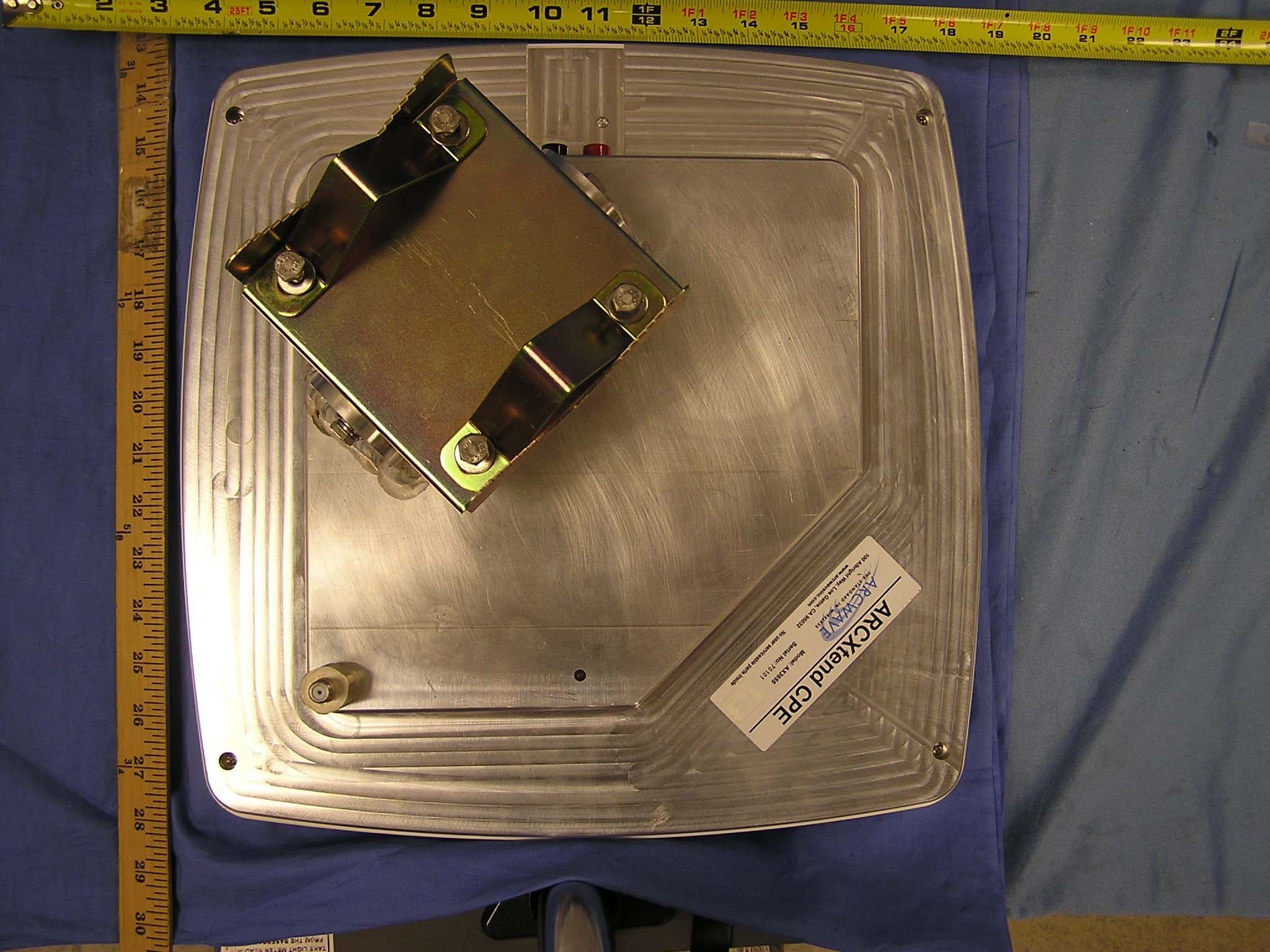
PLRAX365500
Jun 21, 2006Point to Multipoint Wireless Internet System
Equipment Class
DTS - Digital Transmission System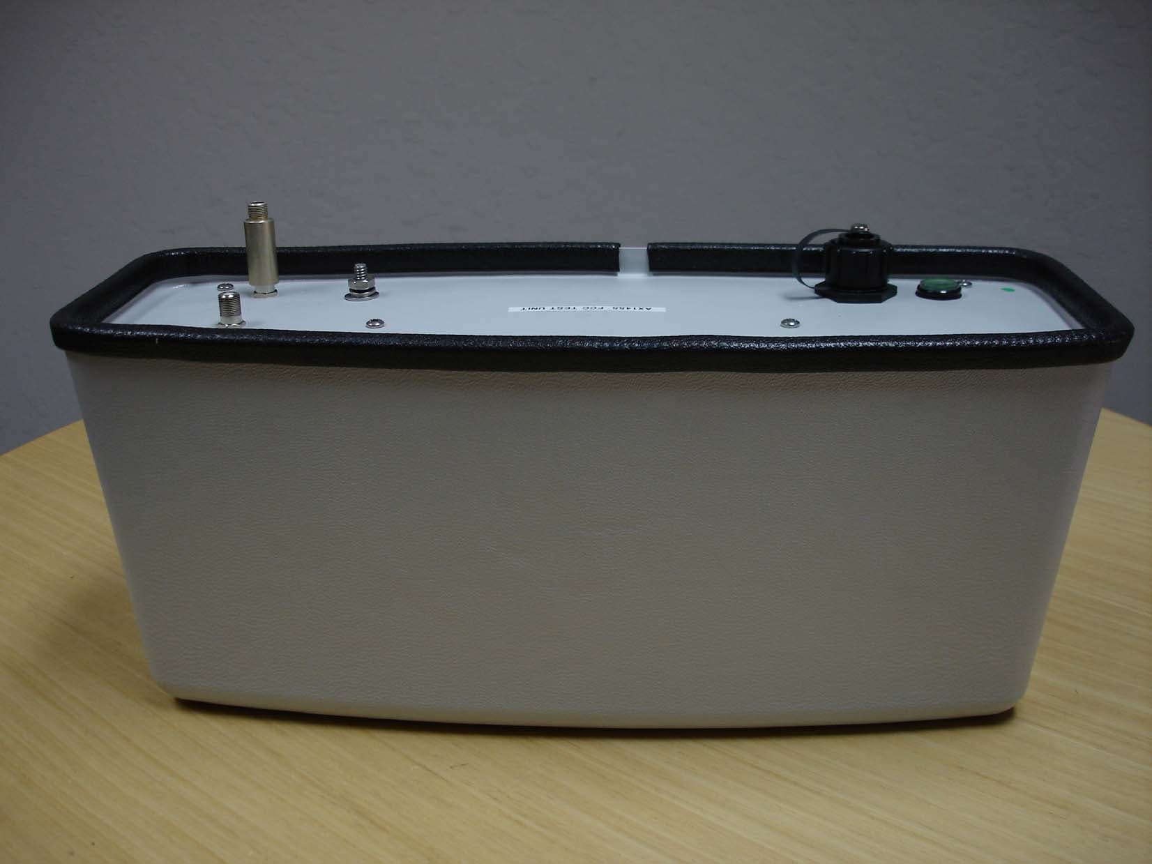
PLRAX145500
Sep 14, 2005ArcXtend TM
Equipment Class
DTS - Digital Transmission System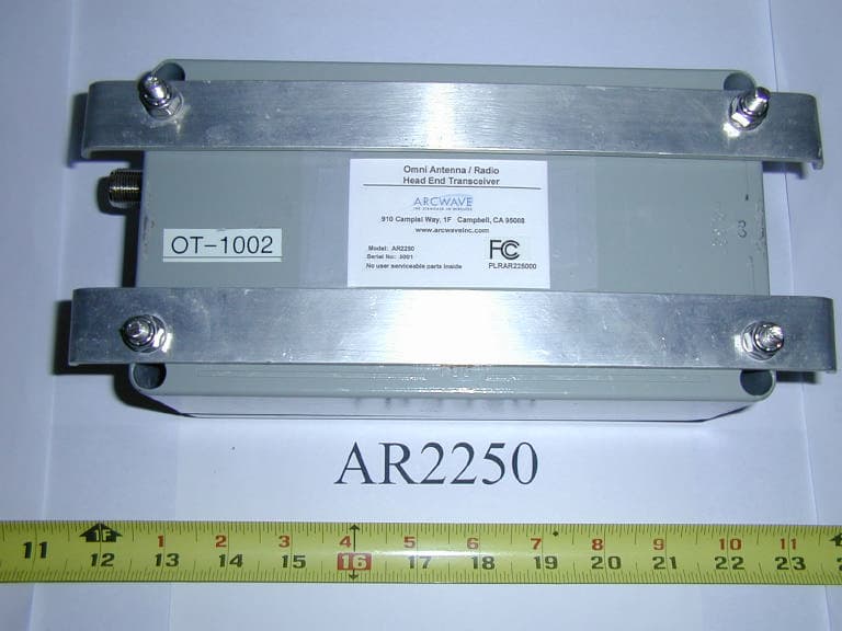
PLRAR225000
Jan 13, 2004Downstream Transmitter - Omnidirectional
Equipment Class
DTS - Digital Transmission System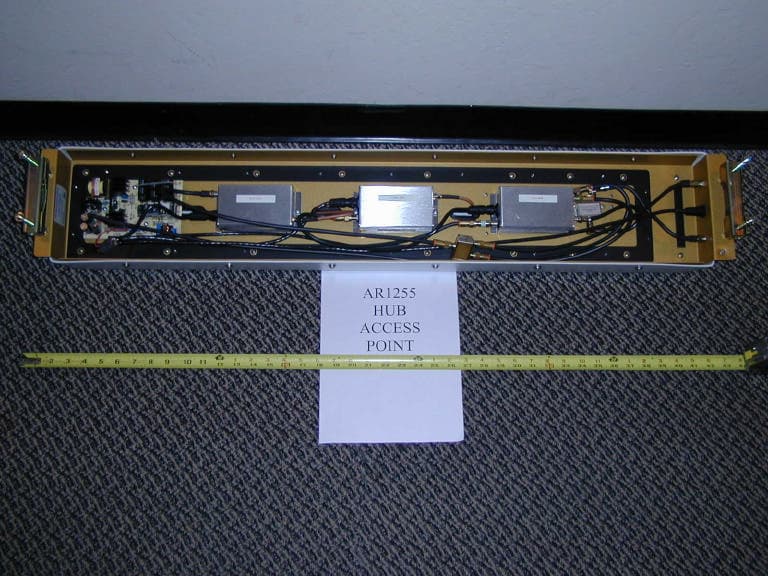
PLRARC12550
Jan 04, 2004Point To Multipoint Wireless System
Equipment Class
DTS - Digital Transmission System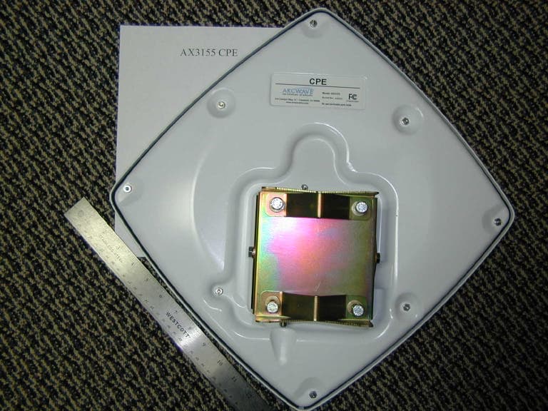
PLRAX315500
Dec 22, 2003Point To Multipoint Wireless System
Equipment Class
NII - Unlicensed National Information Infrastructure TX