PNWDVC-100Digital Voice Camera
Intermagic Corp.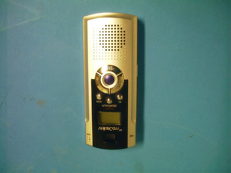
Click to zoom
Application Details
- Equipment Class
- JBP - Part 15 Class B Computing Device Peripheral
- Date of Grant
- Jul 23, 2001
- Application Purpose
- Original Equipment
- Date of Application
- Jul 23, 2001
- Equipment Note
- Digital Voice Camera
- Company
- Intermagic Corp.
- Country
- South Korea
Documents & Files
Document Text
Text extracted from the exhibit documents filed with the FCC. Open a document above to read the original.
ID Label/Location Info
FCC ID Label Sample VoiceCam TM DVC-100 InterMagic Corp. FCC ID : PNWDVC-100 Remark : The labelling requirements, 15.19, will be met by printing on the box since the DUT is small to print of statement.
ID Label/Location Info
FCC ID Label Location Information Label
Test Report
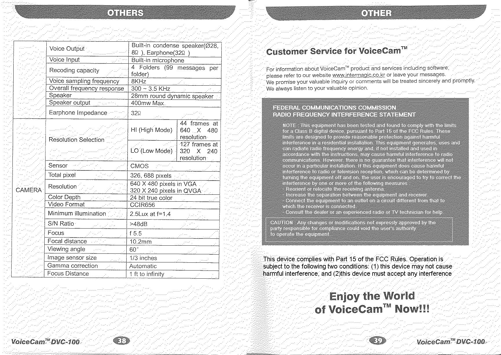
IST Co., Ltd. EMC LABORATORY TEST REPORT NO. : 01-IST-038 1 of 15 Emission Test Report CFR 47 Part 15 Subpart B Test Report File No. : 01-IST-038 Date of Issue :May 17,2001 Model(s) : DVC-100 Kind of Product : Digital Voice Camera Applicant : Intermagic Corporation Address: 7F, Yoojin Bldg., 37-2, Daebang-dong, Dongjak-ku Seoul, Korea, 156-807 Manufacturer : Intermagic Corporation Address: 7F, Yoojin Bldg., 37-2 Daebang-dong, Dongjak-ku Seoul, Korea, 156-807 Test Result Positive Negative Reviewed By Approved By - The test report with appendix consists of 15 pages. - The test result only responds to the tested sample. - It is not allowed to copy this report even partly without the allowance of IST EMC Laboratory. - This equipment as for has been shown to be capable of continued compliance with the applicable technical standards as indicated in the measurement report and was tested in accordance with the measurement procedures specified in ANSI C63.4 1992. G.Chung / Chief IST Co., Ltd. EMC LABORATORY TEST REPORT NO. : 01-IST-038 2 of 15 TABLE OF CONTENTS Table of contents2 Information of test laboratory, Environmental condition, Power used, Product information3 Description of test Conducted Emission4 Radiated Emission5 Summary6 Test conditions and data Conducted emissions0.45 MHz –30 MHzApplicable Test equipment7 Data and plots8-9 Radiated emissions30 MHz –1 GHzApplicable Test equipment10 Data and plots11-13 Appendix A.The DUT Photos14 B.The Accessory15 IST Co., Ltd. EMC LABORATORY TEST REPORT NO. : 01-IST-038 3 of 15 INFORMATIONS OF TEST LABORATORY EMC LABORATORY of IST Co., Ltd. San 21-8, Goan-Ri, Baekam-Myun, Yongin-City Kyonggi-Do, 449-860, Korea TEL : +82 31 333 4093FAX : +82 31 333 4094 ENVIRONMENTAL CONDITIONS Temperature 24°C Humidity 40 % Atmospheric pressure1003 mbar POWER SUPPLY SYSTEM USED Power supply system120 Vac , 60 Hz (For Desktop PC) PRODUCT INFORMATIONS The Device Under Test(DUT) is a digital voice recorder with digital camera. Power RequirementDC 3V (AAA Size) Power Consumption382mW(Play)/387mW(Rec)/500mW(Photo) Dimension 110mm x 45mm x 21mm(WxHxD) Weight80g (including 2pcs of battery) USB UploadMax 12Mbps USB Cable Length1m Recording MediaBuilt in 16MB Flash Memory Voice Recording modeDSPG TrueSPeechTM Voice Input/OutputSpeaker, Earphone / Microphone Camera Resolution44 frames(640X480) / 127 frames(320X240) Camera SensorCMOS Camera Video FormatCCIR656 - EMC suppression device is not used during the test. - For more detail information, see user’s manual. IST Co., Ltd. EMC LABORATORY TEST REPORT NO. : 01-IST-038 4 of 15 DESCRIPTIONS OF TEST Conducted Emissions: The measurement were performed over the frequency range of 0.45MHz to 30MHz using a 50 /50uH LISN as the input transducer to a Spectrum Analyzer or a Field Intensity Meter. The measurements were made with the detector set for "Peak" amplitude within an bandwidth of 10KHz or for "quasi-peak" within a bandwidth of 9KHz. - Procedure of Test The line-conducted facility is located inside a shielded room No.1. A 1m X 1.5m wooden table 80cm height is placed 40cm away from the vertical wall and 1.5m away from the other wall of the shielded room. The R/S ESH3-Z5 and EMCO 3825/2 LISN are bonded to bottom of the shielded room. The EUT is located on the wooden table with distance more than 80cm from the LISN and powered from the EMCO LISN .The peripheral equipment is powered from the other LISN. Power to the LISNs are filtered by a noise cut power line filters. All electrical cables are shielded by braided tinned steel tubing with inner φ 1.2cm. If the EUT is a DC-powered device, power will be derived from the source power supply it normally will be powered from and this supply lines will be connected to the EMCO LISN. All interconnecting cables more than 1m were shortened by non- inductive bundling to a 1m length. Sufficient time for the EUT, support equipment, and test equipment was allowed in order for them to warm up to their normal operating conditions. The RF output of the LISN was connected to the R/S receiver to determine the frequency producing the maximum emission from the EUT. The frequency producing the maximum level was reexamined using Quasi-Peak mode by manual measurement, after scanned by automatic Peak mode for frequency range from 0.45 to 30MHz. The bandwidth of the receiver was set to 10kHz. The EUT, peripheral equipment, and interconnecting cables were arranged and manipulated to maximize each EME emission. 215 >150>40 80 Receiver EUT LISN 80 ≥ 80 80 40 ≥ 80 Measuring apparatus Mains Filter Mains Front side Equipment under test Coaxial cable Artificial mains network Screened room Non-metallic support 80 < Side View > < Concept Drawing > IST Co., Ltd. EMC LABORATORY TEST REPORT NO. : 01-IST-038 5 of 15 DESCRIPTION OF TEST Radiated Emissions: The measurement was performed over the frequency range of 30MHz to 1GHz using antenna as the input transducer to a Spectrum analyzer or a Field Intensity Meter. The measurement was made with the detector set for "quasi-peak" within a bandwidth of 120KHz. - Procedure of Test Preliminary measurements were made at 3 meter using bi-conical and log-periodic antennas, and spectrum analyzer to determine the frequency producing the max. emission in anechoic chamber. Appropriate precaution was taken to ensure that all emission from the EUT were maximized and investigated. The system configuration, mode of operation, turn-table azimuth and height with respect to the antenna were noted for each frequency found. The spectrum was scanned from 40MHz to 300MHz using S/B bi- conical antenna and 300 to 1000MHz using S/B log-periodic antenna. Above 1GHz, linearly polarized double ridge horn antennas were used. Final measurements were made at open site with 3-meters test distance using S/B bi-log antenna or horn antenna. The OATS have been verified in regular for its normalized site attenuation. The test equipment was placed on a wooden table. Sufficient time for the EUT, peripheral e…
Text truncated - open the document above for the full version.
Test Setup Photos
Conducted Emissions – Front View (Upload) Conducted Emissions –Back View (Upload) LISN Radiated Emissions – Front View (Upload) Radiated Emissions –Back View (Upload)
Contact Information
Applicant
Daniel Yoo(General Manger/ R&D)
Test Firm
IST Co., LtdBong Kyoon Bae
Technical Specifications
| # | Rule Parts | Frequency Range | Power Output |
|---|---|---|---|
| 1 | 15B | - | - |
Other Applications from Intermagic Corp.
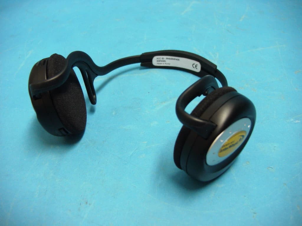
PNWIMP400
May 29, 2003MP3 Player
Equipment Class
JBP - Part 15 Class B Computing Device Peripheral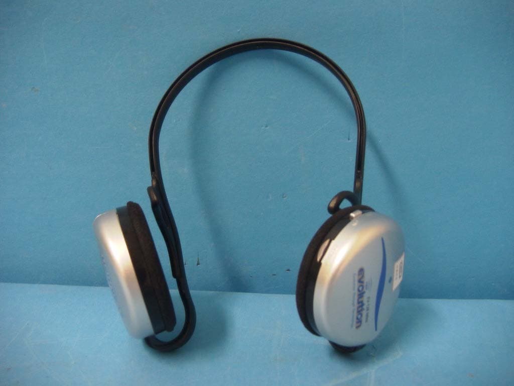
PNWIMP200
Aug 07, 2002MP3 Player
Equipment Class
JBP - Part 15 Class B Computing Device Peripheral
PNWIHP3-064
Jun 27, 2002MP3 Player
Equipment Class
JBP - Part 15 Class B Computing Device Peripheral
PNWDVC-500
Nov 28, 2001DVC-500 Digital Voice Camera
Equipment Class
JBP - Part 15 Class B Computing Device Peripheral