POO-WC45Wii Remote Controller
Mitsumi Electric Co., Ltd.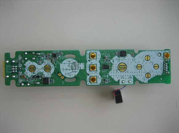
Click to zoom
Application Details
- Equipment Class
- DSS - Part 15 Spread Spectrum Transmitter
- Date of Grant
- Jul 18, 2006
- Application Purpose
- Original Equipment
- Date of Application
- Jul 17, 2006
- Equipment Note
- Wii Remote Controller
- Frequency Range
- 2402.00000000 - 2480.00000000
- Company
- Mitsumi Electric Co., Ltd.
- Country
- Japan
Documents & Files
Document Text
Text extracted from the exhibit documents filed with the FCC. Open a document above to read the original.
Users Manual
IMPORTANT SAFETY INFORMATION: READ THE FOLLOWING WARNINGS BEFORE YOU OR YOUR CHILD PLAY VIDEO GAMES • Some people (about 1 in 4000) may have seizures or blackouts triggered by light flashes or patterns, such as while watching TV or playing video games, even if they have never had a seizure before. • Anyone who has had a seizure, loss of awareness, or other symptom linked to an epileptic condition should consult a doctor before playing a video game. • Parents should watch when their children play video games. Stop playing and consult a doctor if you or your child have any of the following symptoms: Convulsions Eye or muscle twitching Loss of awareness Altered vision Involuntary movements Disorientation • To reduce the likelihood of a seizure when playing video games: 1. Sit or stand as far from the screen as possible. 2. Play video games on the smallest available television screen. 3. Do not play if you are tired or need sleep. 4. Play in a well-lit room. 5. Take a 10 to 15 minute break every hour. Playing video games can make your muscles, joints, skin or eyes hurt after a few hours. Follow these instructions to avoid problems such as tendinitis, carpal tunnel syndrome, skin irritation or eyestrain: • Avoid excessive play. It is recommended that parents monitor their children for appropriate play. • Take a 10 to 15 minute break every hour, even if you don't think you need it. • If your hands, wrists, arms or eyes become tired or sore while playing, stop and rest them for several hours before playing again. • If you continue to have sore hands, wrists, arms or eyes during or after play, stop playing and see a doctor. WARNING - Seizures WARNING - Repetitive Motion Injuries and Eyestrain IMPORTANT SAFETY INFORMATION: READ THE FOLLOWING WARNINGS BEFORE YOU OR YOUR CHILD PLAY VIDEO GAMES To avoid electric shock when you use this system: • Do not use the Wii during a lightning storm. There may be a risk of electric shock from lighting. • Use only the AC Adapter that comes with your system. • Do not use the AC Adapter if it has damaged, split or broken cords or wires. • Make sure that the AC Adapter cord is fully inserted into the wall outlet or extension cord. • Always carefully disconnect all plugs by pulling on the plug and not on the cord. Make sure the Wii power switch is turned OFF before removing the AC Adapter cord from an outlet. Playing video games can cause motion sickness. If you or your child feel dizzy or nauseous when playing video games with this system, stop playing and rest. Do not drive or engage in other demanding activity until you feel better. The Wii is a Class I laser product. Do not attempt to disassemble the Wii. Refer servicing to qualified personnel only. Caution: Use of controls or adjustments or procedures other than those specified herein may result in hazardous radiation exposure. Specifications: Laser Type: Semiconductor laser Laser wave length: 662nm (typ.) (647nm~687nm) Laser power : Max. 0.9mW Numeric aperture: 0.6 NOTE: This is a latex-free product. WARNING - Electric Shock CAUTION - Motion Sickness CAUTION - Laser Device Components Front ViewBack ViewTOP View BACK View Use to turn the Power ON or OFF. Power Button Power LED RESET SYNCHRO SD Card Slot USB Connector Connector for USB device which has a mark like . Green LED illuminates when power is on. The color and the state(steady light/blinking)of the Power Indicator LED indicate system status. Press to restart the game. Press to resister a Wii Remote to be used with the console. Slot where a SD Card is inserted. Disc Eject Button Press to eject a disc Disc Slot Slot where the disc is inserted Blue light is turned on when disc is inserted. Vent Sensor Bar Connector Connector for Sensor Bar (RVL-014). AV Multi Out Connector for AV Cable (RVL-008) or optional cable (Sold separately). DC Input Connector Connector for DC input of AC Adapter (RVL-002 (USA)). Nintendo Gameube Memory Card Slots Slot where Nintendo GameCube Memory ards are inserted. Upper Slot is Slot-A and Bottom slot is Slot-B. Nintendo GameCube Controller Sockets Socket for connecting Nintendo GameCube controllers (including DK Bongo Controller and Mat Controller). From the right: controller Socket 1,2,3,4. Battery Cover Button Battery (CR2032) is built- in. Open cover only when the battery pack has to be removed for disposal or replacement. Inlet LR6(AA)1.5Vx2 0000000000 FCC ID: X XXXXXXX IC:XXXXX-XXXXX Wii RemoteStrap Use to turn the Power ON or OFF Power Button +Control Pad Speaker Wrist Strap Attachment HOME 1 Button 2 Button Player LED Connector for External Extension device such as Nunchuk and Classic Controller. External Extension Connector -Button (minus(-) button) +Button(plus(+) button) A Button B Button C Button Sensor Bar Plug DC JACK AC Plug Z Button Nunchuk Plug Control Stick Battery cover SYNCHRO Press to register a Wii Remote to be used with the console. For attachment of a wrist strap. Connects to 120V AC wall outlet. AV Multi Out ConnectorPlug Connects to AV Multi Out connector on back of the Wii. Connects to DC input Connector on back of the Wii. Components Front View TOP View View Back View Video(Yellow) Audio Left(White) Audio Right(Red) Setting a Wii Remote Setting a Sensor Bar TV INPUT VIDEO IN AUDIO IN LEFT RIGHT 1. Connecting AV cable Before connecting 2. Connecting Sensor Bar 3. Connecting AC Adapter System set up S Y S T E M O P E R AT I O N Turn your TV on. If the console is connected to your VCR, turn it on also and set the TV to VCR Mode. Chose Disc channel and press A button to confirm. For details on subsequent operations, see the instruction manual of the specific game. Insert the Wii disc or Nintendo GameCube Disk into the Disc slot of the Wii console. Then power goes on automatically. Starting a game 1. 2. 3. Push the Disc Eject Button and remove the Game Disc from the console. REMOVING A GAME DISC VIDEO Wii Game Disc or Nintendo GameCube Disk WARNING - Seizures WARNING - Repetitive Motion Injuries and Eyestr…
Text truncated - open the document above for the full version.
External Photos
MITSUMI ELECTRIC CO., LTD. FCC ID: POO-WC45 IC Certification Number: 4250A-WC45 Page 1 of 1
Internal Photos
MITSUMI ELECTRIC CO., LTD. FCC ID: POO-WC45 IC Certification Number: 4250A-WC45 Page 2 of 2 MITSUMI ELECTRIC CO., LTD. FCC ID: POO-WC45 IC Certification Number: 4250A-WC45 Page 1 of 2
Test Report
Report No.:Z01C-06240 Page 2 of 57 ZACTA Technology Corp. FCC ID:POO-WC45 FCC 15C Rev.2.0 Table of contents 1. Summary of Test Results..................................................................................................................................................... 5 2. Equipment description......................................................................................................................................................... 6 2.1 EUT information......................................................................................................................................................................6 2.2 Operating channels and frequencies. ......................................................................................................................................7 2.3 Operating flow .........................................................................................................................................................................8 2.3.1 Operating condition...........................................................................................................................................................8 2.3.2 Test mode...........................................................................................................................................................................8 3. Configuration information................................................................................................................................................... 9 3.1 Peripheral(s) used ....................................................................................................................................................................9 3.2 Cable(s) information................................................................................................................................................................9 3.3 System configuration...............................................................................................................................................................9 4. Test Instruments................................................................................................................................................................. 10 5. Test Type and Results ........................................................................................................................................................ 11 5.1. 20dB Bandwidth / Occupied Bandwidth.............................................................................................................................11 5.1.1 Test Procedure [ FCC 15.247(a)(1), IC RSS-210 A8.1(1) ] ........................................................................................11 5.1.2 Test Instruments and Measurement Setup ......................................................................................................................11 5.1.3 Limit of Bandwidth at 20 dB below................................................................................................................................11 5.1.4 Measurement Result ........................................................................................................................................................11 5.1.5 Trace Data........................................................................................................................................................................11 5.2. Carrier Frequency Separation ............................................................................................................................................. 12 5.2.1 Test Procedure [ FCC 15.247(a)(1), IC RSS-210 A8.1(2) ] ...........................................................................................12 5.2.2 Test Instruments and Measurement Setup ......................................................................................................................12 5.2.3 Limit of Carrier Frequency Separation ...........................................................................................................................12 5.2.4 Measurement Result ........................................................................................................................................................12 5.2.5 Trace Data........................................................................................................................................................................12 5.3. Number of Hopping Frequencies ....................................................................................................................................... 13 5.3.1 Test Procedure [ FCC 15.247(a)(1)(iii), IC RSS-210 A8.1(4) ] ..................................................................................13 5.3.2 Test Instruments and Measurement Setup ......................................................................................................................13 5.3.3 Limit of Number of Hopping Frequencies .....................................................................................................................13 5.3.4 Measurement Result ........................................................................................................................................................13 5.3.5 Trace Data........................................................................................................................................................................13 5.4. Time of Occupancy (Dwell Time) ...................................................................................................................................... 14 5.4.1 Test Procedure [ FCC 15.247(a)(1)(iii), IC RSS-210 A8.1(4) ] ..................................................................................14 Report No.:Z01C-06240 Page 3 of 57 ZACTA Technology Corp. FCC ID:POO-WC45 FCC 15C Rev.2.0 5.4.2 …
Text truncated - open the document above for the full version.
Test Report
Report No.:Z01C-06240 Page 19 of 57 ZACTA Technology Corp. FCC ID:POO-WC45 FCC 15C Rev.2.0 5.8. Spurious Emissions - Radiated - (9kHz – 25GHz) 5.8.1 Test Procedure [ FCC 15.205/209/247(c), IC RSS-210 A8.5, RSS-Gen 4.7&4.8 ] Radiated emission measurements are performed at 3m distance with the broadband antenna (Loop antenna, Biconical antenna, log-periodic antenna and double-ridged guide antenna). The antenna is positioned both the horizontal and vertical planes of polarization and height is varied 1 to 4 meters and stopped at height producing the maximum emission. As for the Loop antenna, it is positioned with its plane vertical, and the center of the Loop is 1.0meter above the ground plane. Frequency Range: 9kHz –1GHz is scanned and investigated with the test receiver, and above 1GHz, with the spectrum analyzer. The detector function of the test receiver is set to CISPR Quasi-peak mode and the bandwidth is set to 120kHz. Peak and average detectors are used for measurements above 1GHz. The bandwidth of the spectrum analyzer is set to 1MHz. The EUT and support equipment are placed on a 1 meter x 1.5meter surface, 0.8meter height styrene form table. The turntable is rotated by 360 degrees and stopped at azimuth of producing the maximum emission. Interconnecting cables, which hanging closer than 40cm to the horizontal metal ground plane are bundled its excess in center. The highest fundamental frequency generated in the EUT is 2402-2480MHz, therefore the frequency was investigated up to 25GHz, as specified in CFR section 15.33, and at least six highest emissions are reported. The test results represent the worst-case emission for each emission with manipulating the EUT, support equipment, interconnecting cables and varying the mode of operation. Sufficient time for the EUT, support equipment, and test equipment are allowed in order for them to warm up to their normal operating condition. 5.8.2 Test Instruments and Measurement Setup Spurious Emissions Test Instrumentation [Testing below 30MHz] Equipment Company Model Number Serial Number Spectrum Analyzer (100Hz-1.5GHz) Agilent Technologies8568B 2732A03847 Test Receiver (9kHz-30MHz) ROHDE&SCHWARZESHS10 835499/012 Loop Antenna ROHDE&SCHWARZHFH2-Z2 892246/010 N/A RG213 N/A Coaxial cable Fujikura 5D-2W/1m YTCRFC#3R,3C-001 Coaxial Switch Anritsu MP59B 6200331883 Report No.:Z01C-06240 Page 20 of 57 ZACTA Technology Corp. FCC ID:POO-WC45 FCC 15C Rev.2.0 [Testing 30MHz-1GHz] [Testing above 1GHz] Equipment Company Model Number Serial Number Spectrum Analyzer ADVANTEST R3271A 65050042 Preamplifier Agilent Technologies 8449B 3008A01008 Double Ridged Guide Antenna EMCO 3115 9408-4327 HORN Antenna Schwarzbeck BBHA9170 BBHA9170189 Microwave cable Suhner SUCOFLEX 104/15m SUCOFLEX 104/1m 108014/4 108015/4 Equipment Company Model Number Serial Number Spectrum Analyzer (100Hz-1.5GHz) Agilent Technologies8568B 2732A03847 Preamplifier (100kHz-1.2GHz) NOGAWA 5331 060110 Kyoritsu Electrical Wo r ks , L t d . KNM-5002 4N-200-5 Test Receiver (25MHz-1.5GHz) Kyoritsu Electrical Wo r ks , L t d . KCV-6002 4-288-2 Biconical Antenna Schwarzbeck VHA9103/BBA91061488 Log Periodic Antenna Schwarzbeck UHALP9108A 0398 8D-SFA/15m YTCRFC#3R-001 8D-SFA/15m YTCRFC#3R-002 8D-2W/8m YTCRFC#3R-003 Coaxial cable Fujikura 5D-2W/1m YTCRFC#3R,3C-001 Coaxial Switch Anritsu MP59B 6200331883 Report No.:Z01C-06240 Page 21 of 57 ZACTA Technology Corp. FCC ID:POO-WC45 FCC 15C Rev.2.0 Test configuration for Spurious emissions 5.8.3 Limit of Spurious Emission Measurement Field Strength Frequency [MHz] [uV/m] [dBuV/m] 0.009 – 0.490 2400 / F [kHz] 20logE [uV/m] 0.490 – 1.705 24000 / F [kHz] 20logE [uV/m] 1.705-30 30 29.5 30 – 88 100 40.0 88 – 216 150 43.5 216 – 960 200 46.0 Above 960 500 54.0 NOTE: 1. The lower limit shall apply at the transition frequencies. 2. Emission level [dBuV/m] = 20 log Emission [uV/m] 3. As shown in 15.35(b), for frequencies above 1000MHz, the field strength limits are based on average detector, however, the peak field strength of any emission shall not exceed the maximum permitted average limits, specified above by more than 20dB under any condition of modulation. Microwave Cable Microwave Cable Double Ridged Guide Antenna Biconical Antenna Log-Periodic Antenna or Below 1GHz Above 1GHz Coaxial Switch Test receiver Spectrum Analyzer 5D-2W Preamplifier 8D-SFA 8D-2W Preamplifier or Loop Antenna Test receiver Spectrum Analyzer or 8D-2W or HORN Antenna Report No.:Z01C-06240 Page 22 of 57 ZACTA Technology Corp. FCC ID:POO-WC45 FCC 15C Rev.2.0 5.8.4 Sample of field strength calculation Spurious Emission dBμV /m= 20log 10 (μV/m) Limit @147.6MHz = 150μV/m = 43.5dBμV/m Reading = 42.8dBμV Ant. Factor + Cable Loss - Amp. Gain = 14.2 + 3.0 - 30.0 = -12.8dB Total = 42.8 - 12.8 = 30.0dBμV/m Margin = 43.5 - 30.0 = 13.5dB 5.8.5 Measurement Results The minimum margins to the limits are as follows: Channel Frequency [MHz] Pol. [H/V] Antenna Height [m] Table Degree [deg.] Margin [dB] Detecter 1 4803.99 H 1.2 150 4.2 Average 40 4881.99 H 1.0 150 4.4 Average 79 4960.03 H 1.0 115 4.0 Average Note: 1.Emission Level (Margin) = Limit – [Reading + Factor (Antenna + Cable - Amp)] 2.The 6 highest emissions relative to the limits are reported. 3.The EUT was found to comply to the limits of FCC Part15 Subpart C and RSS-210 with a margin of 4.0dB. 4. No emissions were detected in frequency range 9KHz to 30MHz at the 3 meters distance. 5.8.6 Data As for the data of the observed RF profiles, refer to Appendix H. Report No.:Z01C-06240 Page 23 of 57 ZACTA Technology Corp. FCC ID:POO-WC45 FCC 15C Rev.2.0 5.9. Restricted Band of Operation 5.9.1 Test Procedure [ FCC 15.205, 15.209, 15.247(c), IC RSS-210 A8.5 ] The peak power is measured with a spectrum analyzer connected to the antenna terminal, while EUT is operating in transmission mode at the appropriate center frequency. The spectrum analyzer is set to: - RBW=1MHz, VBW=1MHz, Span=Arbitrary setting, Sweep=auto The EUT was set to operate with following con…
Text truncated - open the document above for the full version.
Test Report
Report No.:Z01C-06240 Page 37 of 57 ZACTA Technology Corp. FCC ID:POO-WC45 FCC 15C Rev.2.0 Appendix D Appendix D Time of Occupancy (Dwell Time) Trace Data Report No.:Z01C-06240 Page 38 of 57 ZACTA Technology Corp. FCC ID:POO-WC45 FCC 15C Rev.2.0 Channel Low : 2402.0MHz [Channel 1] DH1 DH3 Report No.:Z01C-06240 Page 39 of 57 ZACTA Technology Corp. FCC ID:POO-WC45 FCC 15C Rev.2.0 Channel Middle : 2441.0MHz [Channel 40] DH1 DH3 Report No.:Z01C-06240 Page 40 of 57 ZACTA Technology Corp. FCC ID:POO-WC45 FCC 15C Rev.2.0 Channel High : 2480.0MHz [Channel 79] DH1 DH3 Report No.:Z01C-06240 Page 41 of 57 ZACTA Technology Corp. FCC ID:POO-WC45 FCC 15C Rev.2.0 Appendix E Appendix E Maximum Peak Output Power - Conducted - Trace Data Report No.:Z01C-06240 Page 42 of 57 ZACTA Technology Corp. FCC ID:POO-WC45 FCC 15C Rev.2.0 Channel Middle : 2441.0MHz [Channel 40] Channel Low : 2402.0MHz [Channel 1] - Test mode in Battery operation (Full charge) - Report No.:Z01C-06240 Page 43 of 57 ZACTA Technology Corp. FCC ID:POO-WC45 FCC 15C Rev.2.0 Channel High : 2480.0MHz [Channel 79] Report No.:Z01C-06240 Page 44 of 57 ZACTA Technology Corp. FCC ID:POO-WC45 FCC 15C Rev.2.0 Appendix F Appendix F Band Edge Compliance of RF Conducted Emissions Trace Data Report No.:Z01C-06240 Page 45 of 57 ZACTA Technology Corp. FCC ID:POO-WC45 FCC 15C Rev.2.0 Channel Low : 2402.0MHz [Channel 1] Channel High : 2480.0MHz [Channel 79] Report No.:Z01C-06240 Page 46 of 57 ZACTA Technology Corp. FCC ID:POO-WC45 FCC 15C Rev.2.0 Appendix G Appendix G Spurious Emissions - Conducted - Trace Data Report No.:Z01C-06240 Page 47 of 57 ZACTA Technology Corp. FCC ID:POO-WC45 FCC 15C Rev.2.0 Channel Low : 2402.0MHz [Channel 1] 30MHz-3GHz 3GHz-26.5GHz Report No.:Z01C-06240 Page 48 of 57 ZACTA Technology Corp. FCC ID:POO-WC45 FCC 15C Rev.2.0 Channel Middle : 2441.0MHz [Channel 40] 30MHz-3GHz 3GHz-26.5GHz Report No.:Z01C-06240 Page 49 of 57 ZACTA Technology Corp. FCC ID:POO-WC45 FCC 15C Rev.2.0 30MHz-3GHz 3GHz-26.5GHz Channel High : 2480.0MHz [Channel 79] Report No.:Z01C-06240 Page 50 of 57 ZACTA Technology Corp. FCC ID:POO-WC45 FCC 15C Rev.2.0 Appendix H Appendix H Spurious Emissions - Radiated - Data Report No.:Z01C-06240 Page 52 of 57 ZACTA Technology Corp. FCC ID:POO-WC45 FCC 15C Rev.2.0 Appendix I Appendix I Restricted Band of Operation Trace data Report No.:Z01C-06240 Page 53 of 57 ZACTA Technology Corp. FCC ID:POO-WC45 FCC 15C Rev.2.0 PeakAverage PeakAverage - 2390.0MHz Horizontal - - 2390.0MHz Vertical - Report No.:Z01C-06240 Page 54 of 57 ZACTA Technology Corp. FCC ID:POO-WC45 FCC 15C Rev.2.0 PeakAverage PeakAverage - 2483.5MHz Horizontal - - 2483.5MHz Vertical - Report No.:Z01C-06240 Page 55 of 57 ZACTA Technology Corp. FCC ID:POO-WC45 FCC 15C Rev.2.0 Appendix J Appendix J Transmitter Power Spectral Density Trace data Report No.:Z01C-06240 Page 56 of 57 ZACTA Technology Corp. FCC ID:POO-WC45 FCC 15C Rev.2.0 Channel Middle : 2441.0MHz [Channel 40] Channel Low : 2402.0MHz [Channel 1] Report No.:Z01C-06240 Page 57 of 57 ZACTA Technology Corp. FCC ID:POO-WC45 FCC 15C Rev.2.0 Channel High : 2480.0MHz [Channel 79]
Test Setup Photos
MITSUMI ELECTRIC CO., LTD. FCC ID: POO-WC45 IC Certification Number: 4250A-WC45 Page 1 of 2 RF Conducted Test Hopping Non-Hopping MITSUMI ELECTRIC CO., LTD. FCC ID: POO-WC45 IC Certification Number: 4250A-WC45 Page 2 of 2 Spurious Test
Contact Information
Applicant
Katsunori Kobari(Mr.)
Test Firm
TUV SUD Zacta Ltd.Shin-ichi Abe
Technical Specifications
| # | Rule Parts | Frequency Range | Power Output |
|---|---|---|---|
| 1 | 15C | 2.40 GHz - 2.48 GHz | 1.25 mW |
Other Applications from Mitsumi Electric Co., Ltd.
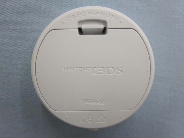
POOCTR012
Feb 07, 2015RFID Product
Equipment Class
DXX - Part 15 Low Power Communication Device Transmitter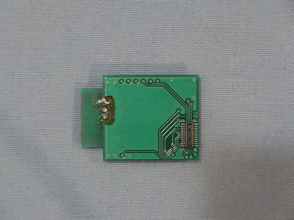
POO-WC75
Jan 07, 2014Bluetooth LE Module
Equipment Class
DTS - Digital Transmission System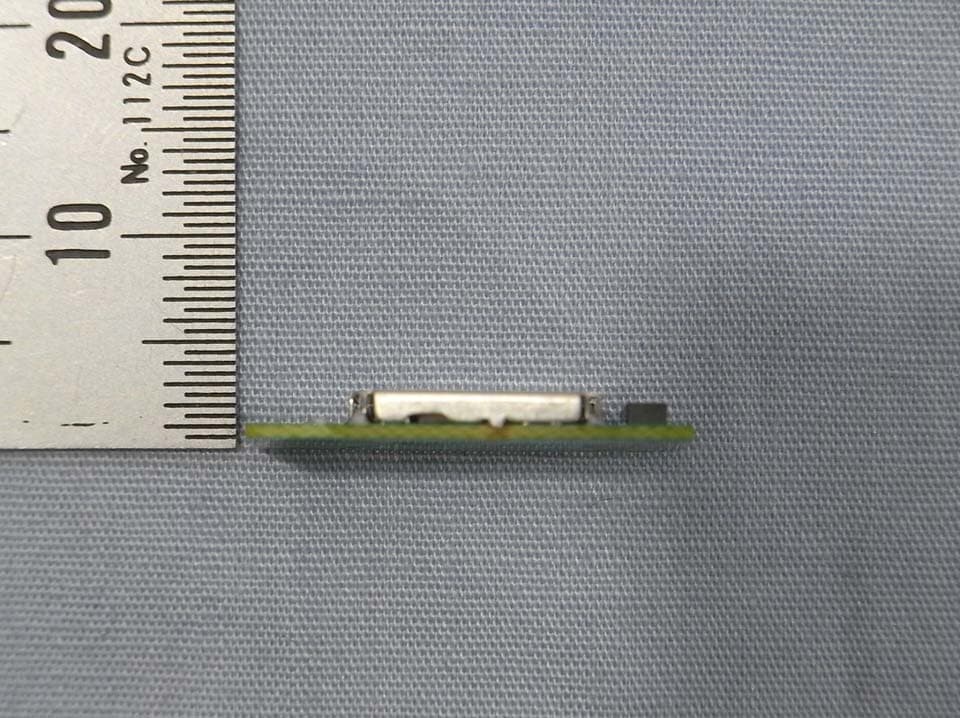
POO-WC69
Apr 24, 2013Bluetooth LE Module
Equipment Class
DTS - Digital Transmission System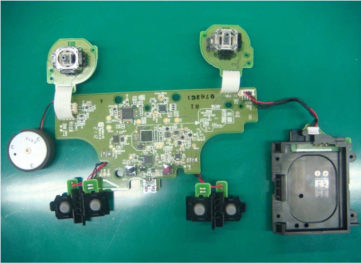
POO-R237999
Jul 10, 2012Remote Controller
Equipment Class
DSS - Part 15 Spread Spectrum TransmitterPOO-DR237973
Mar 24, 2012Remote Controller
Equipment Class
DSS - Part 15 Spread Spectrum Transmitter